
Abstract
This article presents the influence and impact of the gap between the outer and the inner diameter of the slipper on the performance of axial piston pumps. For this, a mathematical model establishing and evaluating the quantities involved in the total power loss is established. Four slippers having a different values of the ratio between their diameters are considered; for which the study and the simulation concerning the fluid film thickness, the forces, the flow and the total power loss between the slipper and the swash plate are developed and compared. After the analysis of all these parameters for different slippers, the results of the simulation show that for each slipper, there are values of the optimum fluid film thickness for which the pump has the minimum in terms of power loss between the slipper and the swash plate. And after the comparison, the favourable ratio between the diameters of the slipper for good lubrication is given. The accuracy between the mathematical model and simulation results is checked, and a discussion is made. Finally, a conclusion based on the results of the lost power is made.
Introduction
The axial piston pump is an essential element of the hydraulic system used in various industrial applications. It is made up of several components connected by various relations to one other, having three major interfaces, among which is the one between the slipper and the swash plate. The slipper is the element ensuring the contact between the piston and the swash plate, it is submitted to several forces which create a perpetual instability; hence, there is a need for good lubrication to both minimize instability and avoid contact between these metals (slipper and swash plate). Thus, the parameters of the slipper play a very important role in the lubrication of this surface. For many years now, a lot of research has been conducted as part of the contact lubrication performance between slippers and swash plate. HL Liu et al. 1 conducted studies on the non-flatness of the metal-on-metal contact conditions taking into account the effects of slipper slip, tangential velocity and tilt. A cluster of three displacement sensors has been embedded in the swash plate to monitor the slipper performance at 30 measured positions by rotating the index plate by Q Chao et al. 2 Studying the optimization of the performance of grooved slippers for aerodynamic hydraulic pumps, the effects of sealing land radius, orifice size and groove on the behaviour of the slipper has been pointed out by J Chen et al. 3 to describe the pressure distribution and the fluid film thickness distribution, allowing them to study the behaviour of the slipper pad. J Zhang et al. 4 introduced the test rig to experimentally investigate the slipper spin in an axial piston pump, concluding that the slipper spin is in existence and its speed is approximately equal to shaft speed under test conditions.
During the operation of the pump, some of the power is lost, of which a significant amount comes from the contact surface between the slipper and the swash plate. This power loss in the slipper–swash plate interface is in one way due to the viscous friction between the slipper and the swash plate and in the other way due to the leakage flow through the slipper and the displacement chamber. Koc and Hooke5,6 investigated experimentally the effects of the clamping ratio and orifice size on the performance of slippers; by considering the design of partially hydrostatic slipper bearings, they evaluated the clamping ratio for three different values of the ratio between the slipper’s diameters. Canbulut and colleagues7,8 considered the dynamic conditions to study experimentally and the neural network model to study the performance of non-grooved slipper for different dimensions. They obtained some important characteristic values, such as ideal power expression, viscous moment loss, viscous fluid leakage, bearing rigidity in a dimensionless form and examined these characteristic parameters in the variable working conditions. AT Schenk 9 used advanced fluid thermal-structure, rigid body dynamics model to investigate power loss in slipper–swash plate interface of two different axial piston pumps under a range of operating conditions. By an analytical model based on the change of total power loss in function of the fluid height, they have determined the value of the optimum height by emphasizing the influence of the rotation speed and the pressure on the latter.
K Choudhuri and P Chakraborti 10 conducted a study showing the impact of slipper dimensions on the load capacity of the pumps concluding that the load-carrying capacity has a direct relation with the pressure, land area, conical angle of the land and the sleeper speed. M Elashmawy 11 proposed a type of design that eliminates the slipper to replace a ball housed in the piston head in order to minimize the angle of action of the cam. Based on the approximate estimate, he pointed out that expected power reduction of this proposed design is about 30% and requires further investigation for an accurate assessment of the reduction. The ‘triple land slipper’ model has been proposed and studied by AT Schenk 9 with which very profitable results have been obtained with regard to the lubrication of the oil film between the slipper and the swash plate.
H Tang and colleagues12,13 studied the influence of slipper ratio and orifice length on the film thickness, film temperature and load-carrying capacity. From a general point of view, research on slipper design to improve lubrication between the slipper and swash plate contact is well advanced. However, little analysis and attention are given to the impact of the difference between the outer and the inner diameter of the slipper (as located on Figure 1) or their ratio on the total power loss.
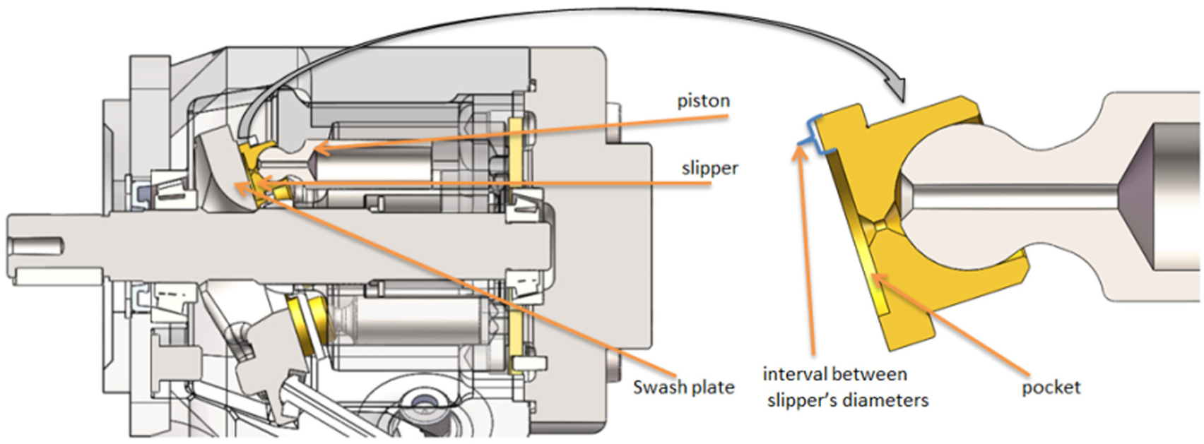
The location of the slipper in the axial piston pump.
Until now, the researches on the loss of power between the slipper and the swash plate do not clearly discuss the sources of this loss of power and the direct relationship that it has with the slipper sealing land.
This article is subject to the study of the optimization of the contact surface between the slipper and the swash plate implying the understanding of the behaviour of the parameters involved in the total power loss. The study and comparison of the distribution of the fluid film thickness, the pressure, the leakage and the power loss between the slipper and the swash plate are made.
This article is organized as follows: the mathematical model expressing the quantities involved in the total power loss between the slipper and the swash plate as the functions of the inner and the outer diameter of the slipper is established (the Reynolds equation is solved) for four slippers having different sealing lands in section ‘Mathematical model’. Section ‘Numerical model and simulation’ establishes the numerical model starting from the process to the simulation results of the oil thickness, flow, forces, pressure (by solving the Reynolds equation in MATLAB) and the power loss between the slipper and the swash plate for four slippers having a different sealing land. Section ‘Accuracy and discussion’ presents a discussion and the accuracy between the mathematical model and simulation results. Section ‘Conclusion’ presents conclusions and discussions.
Mathematical model
The total power loss between the slipper and the swash plate is all of the power lost due to the flow and due to the friction forces. However, the determination of these two variables, that is, the flow and the friction force, emanates in advance the determination or the evaluation of the fluid film thickness between the slipper and the swash plate. This mathematical part first begins with the determination of the height, the flow, the pressure and the forces applied and the pressure on the slipper, in order to deduce the total power loss between slipper and swash plate in function of the diameters of the slipper.
Fluid film thickness
Following the action of the multiple forces exerted on the slipper, it is driven to perform a lot of movements. Its slight rotation around the X axis causes its inclination around the Y axis and vice versa. Following the pressure of the stocking, at any position given during the operation of the pump, the oil film between the slipper and the swash plate is wedge-shaped, as shown in Figure 2.
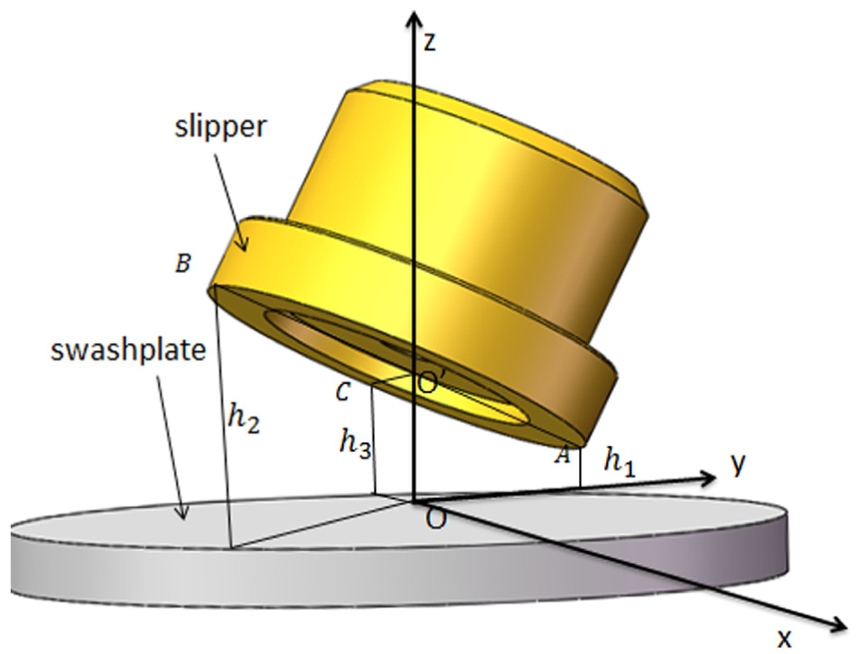
Wedge-shaped oil film between slipper and swash plate.
The instantaneous lubricating oil film height h can be expressed as a function of three different points h1, h2 and h3 on the outer edge with interval of 120° from each other, assuming that the slipper and swash plate surfaces are ideally smooth and neglecting the deformation of the slipper and the swash plate;14,15 also due to the tilting moments, the oil film between the slipper and swash plate is usually wedge-shaped, as shown in Figure 3. The film thickness at an arbitrary point (r,θ) can be calculated as

By reducing the positions to cylindrical coordinates

where
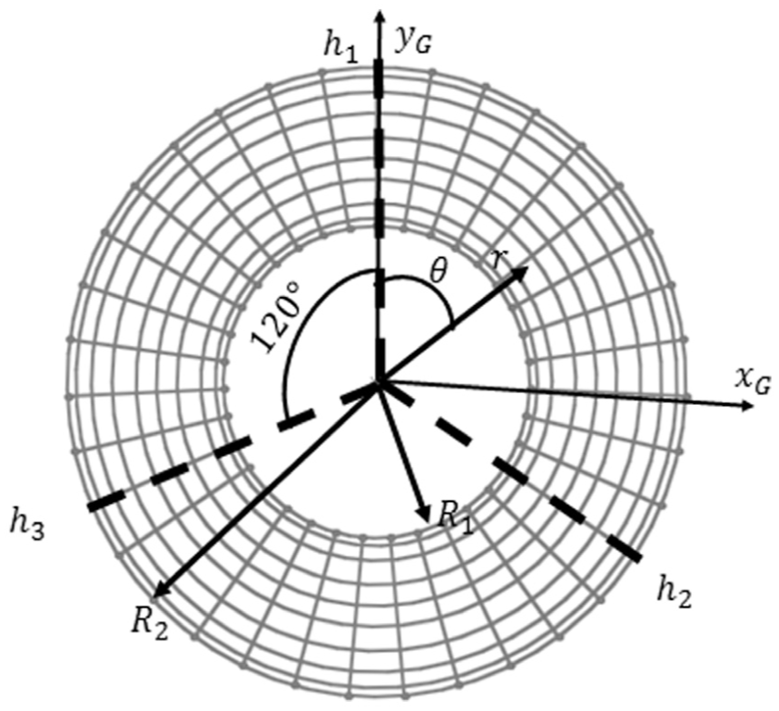
Wedge-shaped of the oil film between slipper and swash plate.
The forces applied on the slipper
The main role of the slipper is to transfer all the forces applied to the swash plate as fluently as possible. The fluid under pressure in the displacement chamber exerts an axial fluid force on the piston–slipper assembly and generates a reaction force on the swash plate. Given that this study is based much more on the influence of slipper parameters on power loss, more attention will be given in this section to the forces that are a function of slipper diameters and/or involved in the expression of the total power loss between the slipper and swash plate interface. Thus, these aforementioned forces are illustrated in Figure 4.

Forces applied on the slipper: (a) force applied on the slipper and (b) single slipper top view.
In Figure 3,
It is important to specify that our attention will be more focused on the forces indicated by the red arrows in Figure 4, that is, those directly related to the diameters of the slipper. The swash plate exerts a reaction force on the slipper and its expression which has been developed by Wondergem 16 can be transformed and rewritten as a function of the slipper diameters, as shown in equation (3)

where D is the outer diameter of the slipper, d is the inner diameter of the slipper and
Since the square function increases faster than the logarithmic function, the expression of the force given by equation (3) increases with an increase in the difference between the diameters of the slipper. This shows that the swash plate reaction force can be considered as a function of two variables, which are the pressure
Pressure force

Under ideal running condition without metal-to-metal contact, friction between the slipper and swash plate is mainly caused by the shear stresses of the fluid, which is affected by the film thickness and oil viscosity. The viscous friction force is caused between the piston and the cylinder block as shown in Figure 4. Its mathematical expression which has been derived by D Gronberg 18 can be rewritten as a function of the slipper’s diameter as follows

where
The thermal wedge bearing force and the equation of the clamping force on the sealing surface of the slipper developed by DS Wen 19 can be rewritten according to the diameter of the slipper, respectively as shown in equations (6) and (7)
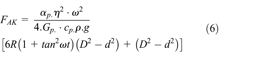
where
A centrifugal force

with

where
Leakage flow
The flow of fluid between the slipper and the swash plate is mechanically influenced by the forces acting on the slipper. The flow depends strongly on the value of the difference between the outer and the inner diameter, as well as the pressure difference between the slipper and the swash plate. According to the leakage theory of parallel discs, the leakage

where h is the clearance between the slipper and the swash plate,
Pressure distribution
Since the fluid film thickness between the slipper and swash plate is very small (on the order of micrometres) compared at the base of the slipper, the flow can be regarded as the laminar flow. Therefore, the Reynolds equation of lubrication applied between the slipper and swash plate gap when the slipper moves tangentially with a velocity U spins with an angular velocity
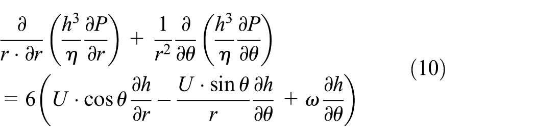
To evaluate and understand the effect of the slipper parameters on the pressure between the slipper and the swash plate, let’s consider the viscosity of the fluid constant, a slipper without inclination and no relative movement between the slipper and the swash plate, and equation (10) is simplified. Only the first term on the left remains, which is equal to zero, and can be simplified as follows

After two successive integrations of equation (11)

where

For z = 0, U = 0, r = R1, P = P1 and z = h, U = 0, r = R2, P = P2

where U is the velocity component in the X direction;
According to the illustration given in Figure 5(a), the flow between the slipper and the swash plate can be determined according to the surface integration of the speed as follows

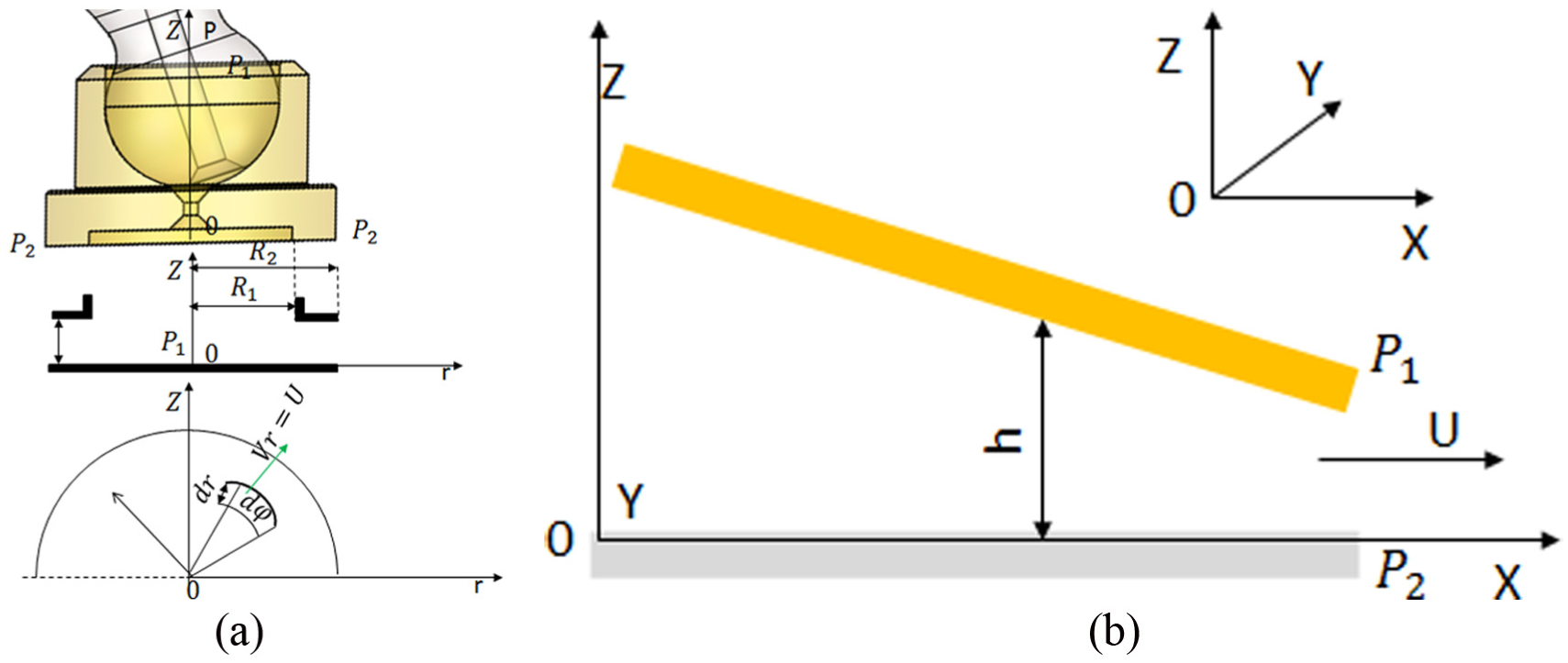
A hydrostatic gap between slipper and swash plate/variable gap height: (a) hydrostatic slipper body diagram and (b) velocity boundary condition.
From equation (14), we can easily draw the pressure gradient and integrate it as follows


Then, equations (16a), (16b) and (17) permit us to calculate the flow Q, and it can be drawn as a function of the pressure difference as follows

Subsequently, the expression of the pressure as a function of radial displacement can be obtained by direct integration of equation (16a) as follows
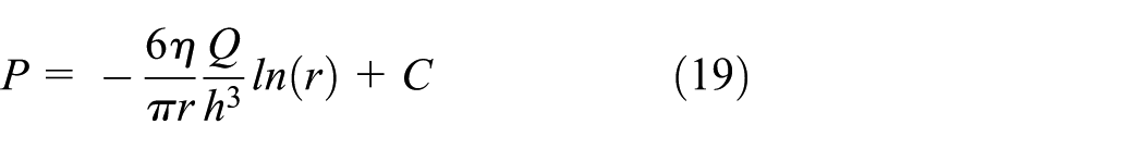
Here, C represents the integration constant. Applying the same initial conditions, such as for z = 0, U = 0, r =R1, P = P1 and z = h, U = 0, r = R2, P = P2

In equation (20), C can be drawn and substituted in equation (19) to get the following expression

Substituting Q for its expression of equation (18) in equation (21), we obtain

where r varies between the inner and the outer radius of the slipper. From equation (18), the pressure difference increases with the ratio between the slipper’s ratio. The study of pressure profiles for the four different slippers is developed using the resolution of the Reynolds equation in the simulation part. The pressure boundary conditions of the Reynolds equation (10) can be expressed as

where
The total power loss between slipper and swash plate
The total power lost between the slipper and the swash plate is caused by the multiple movements of the slipper on the swash plate. As the slipper lifts away from the swash plate and full fluid film lubrication is established, the volumetric flow out of the slipper pocket, as well as the viscous friction between the slipper and swash plate, is 9

When the slipper lifts off the swash plate and full fluid film lubrication is established, then the loss due to the volumetric flow out of the slipper pocket


The total loss of power between the slipper and the swash plate constitutes losses due to the gap and losses due to friction. Thus, starting from equations (25a) and (25b), the total power loss noted

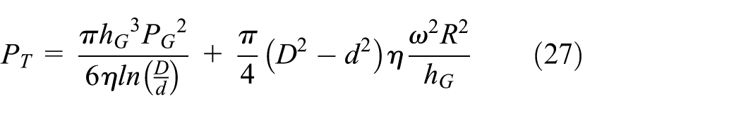
Considering the thickness of oil as a variable and applying the total differentiation to equation (27), then solving equals to zero; we get the expression of the optimal fluid film thickness noted

This expression (28) depends largely on the diameters of the slipper. This equation means that, for each value of the ratio between the diameters of the slipper, the interval of the optimal height in which is the minimum in power loss changes.
Numerical model and simulation
As mentioned above, several forms have been adopted by the slipper for the numerical study and simulation, due to its widespread use in current industries, the slipper with only one pocket and only one land is considered as Figure 6 illustrates. To understand the real impact of slipper parameters (ratio between diameters) in optimizing pump performance by lubricating the contact surface between the slipper and the swash plate, we give the geometric properties held constant for different slippers during the study in Table 1. Thereafter, four different slippers are considered. All the four slippers have the same outer diameter with a value of 25.5 mm. These slippers differ in their internal diameters, respectively, having values of 10, 12.75, 15 and 17.85 mm. In all cases, the value of the dynamic viscosity of the oil is 0.0705 Pa s. The variation and the behaviour of the quantities such as the fluid film thickness, the forces, the flow, the distribution of the pressure and the total power lost between the slipper and the swash plate are simulated thereafter.
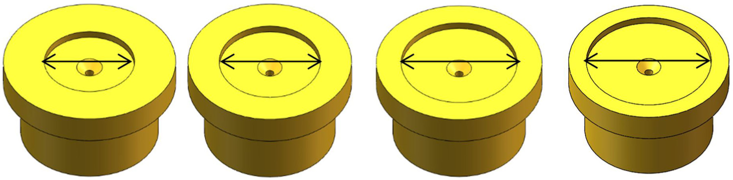
Free body slipper with four different values of inner diameter.
Values of the parameters kept constant.

The simulation in MATLAB debuts by a random choice of the initial value of the oil film and then obtains the distribution of the pressure in the first loop (Figure 7). The iterative method (Newton’s iterative method) is therefore used to resolve non-linear equations in the second loop. At the end, the oil thickness taken initially is updated during the rotation of the slipper on the swash plate. 23 The Reynolds equation is used to calculate the pressure field in the oil film.

Flowchart of numerical simulation model.
Fluid film thickness
The height of the oil film between the slipper and the swash plate as defined in equation (2) is described by the distance between slipper and swash plate in three different points as illustrated in Figure 2, which is arranged on the outside diameter of the slipper. The profiles of the distribution of the height of oil for the four different slippers are illustrated by Figures 8 and 9.

Lubricating oil film thickness (ϕ = 60°).

Gap height between slipper and swash plate function of shaft angle (ϕ = 60°).
The distribution of the film of oil between the slipper and swash plate obtained for the four different slippers as mentioned above is illustrated in Figure 8. These different distributions are obtained for the same value of the angle of rotation ϕ = 60°.
Figure 9 represents the distribution of the height of the fluid film between the swash plate and the slipper as a function of the angle of rotation and the time.
The forces applied on the slipper and function of the diameters of the slipper
In order to verify the influence of the ratio of the slipper diameters on the forces as expressed analytically above, the numerical study through MATLAB is done. We are mainly interested in three forces such as friction force, piston force and inertia force, which are mathematically related directly to the diameters of the slipper. The results of the numerical analyses, giving the variation of these forces as a function of time, for the four different slippers considered are given by the following figures.
Figure 10 shows how the amplitude of the oscillation of the inertial force varies for each different slipper. For the same periodicity, the slipper with the greatest value of the ratio between its diameters (d = 10 mm) has the largest amplitude value. The slipper with the smallest value of the ratio (d = 17.85 mm) has the largest amplitude value. This means that the slipper having a big ratio between its diameters is the most stable, but at the same time, it has the greatest value of the friction force (see Figures 11 and 12).

Inertia force for the four different slippers.
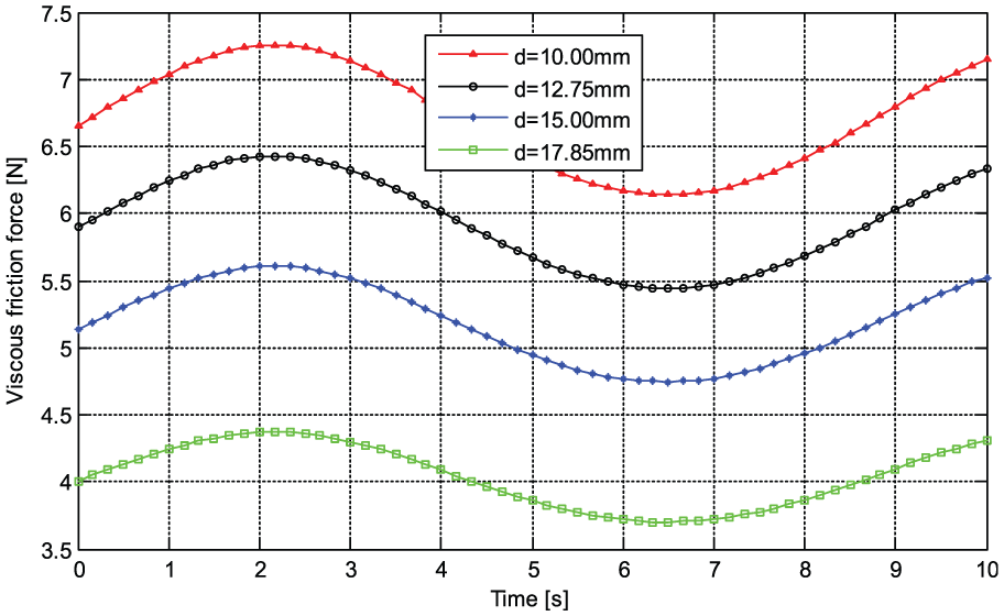
Viscous friction force for the four different slippers.

Axial piston force for the four different slippers.
Leakage flow
According to the mathematical formula of the movement developed above, the flow between the slipper and the swash plate is influenced by the parameters of the slipper. The flow curve for four different slippers is shown in Figure 13.

The flow graph of the slipper–swash plate for four slippers with different ratios of diameters.
The value of the flow is very high for the slipper having a large value of the inner diameter (d = 17.85 mm) and is small for that having a small value of the inner diameter (d = 10 mm).
The pressure distribution
In order to validate the analytical equations of pressure and to understand the diameters impaction by the ratio of the slipper, a numerical model has been developed for the solution of Reynolds equation, which is given by equation (10). The profiles of the pressure distribution between the slipper and the swash plate for the four different slippers are presented in Figure 14.

The distribution of pressure between the slipper–swash plate for the four different slippers: (a) pressure profile for d = 10 mm, (b) pressure profile for d = 12.75 mm, (c) pressure profile for d = 15 mm and (d) pressure profile for d = 17.85 mm.
The total power loss
The total power loss in the axial piston pump is an accumulation of dissipations between its various components and also because of the different movements that it produces during its operation. The total power loss between the slipper and the swash plate is a loss due to the loss of the flow and that due to the friction forces; the crucial parameter is the height of the gap between the slipper and the swash plate. According to the mathematical formulas developed above, the two different sources of loss of power do not vary proportionally according to the diameters of the slipper. When the ratio or the difference between the diameters of the slipper increases, the loss due to the forces of the friction increases while the loss due to the flow decreases. Slippers with additional bearing surfaces also contribute to minimizing mechanical losses by enabling hydrodynamic effects on a surface. 24 The curves showing the variation of the total power between the slipper and the swash plate for the four different slippers are shown in Figure 15.

Analytical slipper power losses versus fluid film thickness for the four different slippers.
The variation of the total power lost as a function of the thickness of the fluid film between the slipper and the swash plate studied in the document referred to in the AT Schenk 9 showed the interval in which the value of the oil thickness must be to have the minimum of total power loss. However, this interval is not fixed. According to the figures above, this interval depends considerably on the structure of the slipper. In addition to this, the axial and tangential friction force, the losses of torque due to the viscous friction force, the total leakage and the corrugation of flow on both ports represent the main sources of total power lost in axial piston pumps as indicated above. For a little more clarity in the comparison, Figure 16 illustrates the variation of all four slippers.
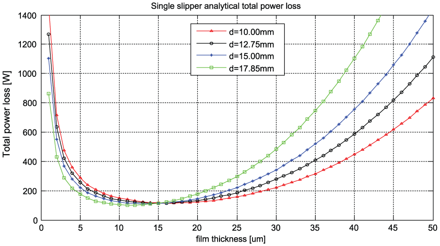
Analytical slipper total power losses versus fluid film thickness.
Accuracy and discussion
The consistency between the mathematical model and analytical simulation is very good. Figure 13 presenting the simulation of the flows shows that the value of the flow for the slipper with a large value inner diameter (d = 17.85 mm) is more high. Simulation matches well with the mathematical term of the flow described by equation (9), because, in this equation, the value of flow (Qs) increases with the increase in the inner diameter (d). In Figure 16, presenting the variation of the power loss for the four slippers, it is observed that from certain values of the oil film, the curve of the power loss rises abruptly for the slipper that has a great value of the inner diameter and a slow increase for the one having a small value of the inner diameter. This reflects exactly what the two different sources of loss of power defined by equations (24), (25a) and (25b) express. When the inner diameter (d) increases, the power loss due to the leakage (equation (25a)) increases but the loss due to the friction force (equation (25b)).
Conclusion
At the end of this analysis, it is clear that the parameters of the slipper play a very important role in the total power loss between slipper and swash plate in the axial piston pump. All the parameters involved in the total power loss were evaluated and studied with respect to the slipper diameters. The variation of the total power loss as a function of the fluid film thickness between the slipper and the swash plate is strongly influenced by the ratio of the diameters of the slipper. This study has clearly shown that the range of variation of the optimal height with minimum power loss between the slipper and the swash plate depends considerably on the ratio of the diameters of the slipper. For the four different slippers with the same characteristics and conditions of operations except for the ratio of their diameters as considered in this article, the minimum value of the power loss is minimal for the slipper having the smallest value of the ration. But the interval of the optimal height in which the value of the power loss is below 200 W is more extended for the slipper having the greatest value of the ratio between its diameters. It has been shown that the total power loss for the slipper having the value of the ratio 2.55 (d = 10 mm) is below 200 W for
Footnotes
Handling Editor: Noel Brunetiere
Declaration of conflicting interests
The author(s) declared no potential conflicts of interest with respect to the research, authorship and/or publication of this article.
Funding
The author(s) disclosed receipt of the following financial support for the research, authorship, and/or publication of this article: This work was supported by the National Natural Science Foundation (grant number 51205368) and the Natural Science Foundation of Zhejiang Province (grant number LY17E050001).