
Abstract
The rolling control of a car that focuses on reducing the roll angle passively has limited performance of increasing handling stability, passing speed, ride comfort, and rollover prevention while turning. This project presents a method for controlling an automobile to tilt toward the turning direction using active suspension. A 6-degree-of-freedom vehicle model with a 2-degree-of-freedom steering model and a 4-degree-of-freedom tilting model is established. The active tilt sliding mode controller, which causes zero steady-state tilt angle error, is established after the desired tilt angle is determined by dynamic analysis. Simulation results confirm the effectiveness of the control method. The proposed controller reduces the perceived lateral acceleration and the lateral load transfer rate, thereby effectively improving handling stability, ride comfort, and vehicle speed, meanwhile decreasing the possibility of rollover while turning.
Keywords
Introduction
Traditional passive suspension (PS) prevents vehicle roll by enhancing suspension stiffness and installing a stabilizer bar but decreases vehicle ride comfort and is unable to prevent rolling and improve ride comfort simultaneously. Active or semi-active roll control can solve this contradiction. A control method performs active or semi-active control by installing an actuator in series with a stabilizer bar,1,2 and another method conducts attitude control on the vehicle body to control rolling through active or semi-active suspensions.3–6 Active or semi-active suspensions can also be used to control rollover; however, this control strategy is not the same as the anti-roll control when the vehicle travels normally. 7 In addition, hydraulically interconnected suspensions also have a good effect on anti-roll. 8 Vehicle roll deteriorates ride comfort and handling stability and even leads to rollover when turning. However, these roll controls mostly focus on reducing the roll angle or causing zero roll angle at most.9,10 In the case of quasi-static rollover, the rollover threshold of a rigid car without roll can be improved at most by approximately 10% compared with a normal vehicle considering suspension and tire deformation. Thus, the effectiveness of these roll controls mentioned above is limited in terms of improving vehicle performance when steering.
A vehicle will roll outwards due to the centrifugal force while turning. However, if the vehicle can tilt inwards similar to a bicycle, this reverse tilt can cause the moment generated by gravity to offset that generated by the centrifugal force, and therefore reduce the lateral load transfer rate (LTR) and the lateral acceleration experienced by passengers even to zero. Reverse tilt can extremely improve handling stability, ride comfort, vehicle speed, and rollover prevention when turning, and improve maneuverability and agility of manipulation. Meanwhile, reverse tilt can not only improve performance while turning but also control the attitude of the vehicle and reduce the transversal load transfer. Moreover, the transversal load transfer on the front or rear axles can be changed when actively tilting the front or rear suspension alone. Active tilting technology 11 was applied on railway vehicles in the early 1980s and started to be widely used in high-speed trains after decades of research and development. The speed of the train is increased without changing existing track lines and infrastructure. 12 Another application of active tilt control is the narrow commuter vehicle, the width of which is only half that of the common car. This vehicle, which has aroused great interest among researchers in recent decades, is suitable for driving in urban areas. The vehicle needs the active tilt technique to ensure ride stability because it is narrow and has a high center of gravity (c.g.). Some researchers have developed some prototype vehicles.13–15
Research on automobile active tilt control started fairly late, and only few studies can be found. Wang and Shen 16 explained the feasibility of actively tilting the vehicle inwards via active suspension. Considering vehicle ride comfort, a robust H-infinity active tilt integrated controller was designed. The simulation results showed that lateral acceleration can be reduced via effective active tilt control. Taking zero acceleration as the control target, Youn et al. 17 designed an attitude-tracking controller to control vehicle attitude by active tilt control that is based on active suspension. The simulation results verified the feasibility of the controller. The automobile active tilt control needs further research to find some more efficient control strategies and evaluation methods, as well as further explanation for the significance of active tilt control.
This article presents a sliding mode controller (SMC) for controlling automobile to tilt toward the turning direction via active suspension. The perceived lateral acceleration and the LTR are proposed for evaluating and explaining the significance of this active tilt control.
Vehicle active tilt model based on active suspension
A 6-degree-of-freedom (DOF) vehicle model with a 2-DOF steering model and 4-DOF tilt model aims to study the dynamics of active tilt during steering. The established vehicle model is shown in Figure 1. From D’Alembert’s principle and referring to the work of Jin et al., 18 the equations of the vehicle model are as follows:
Vehicle steering dynamics equation


Dynamics equation of sprung mass vertical movement

Dynamics equation of vehicle tilt movement

Dynamics equation of unsprung mass vertical movement


where

where

Steer–tilt dynamic model of the full vehicle: (a) lateral and yaw movement and (b) tilt and vertical movement.
Design of sliding mode variable structure controller
Desired tilt angle for active tilt control
When a vehicle is turning, it is tilted inward actively to cause the vehicle body gravity generating roll moments which can offset the moments generated by the centrifugal force. Thus, the value of the lateral acceleration experienced by passengers is equal or close to zero. The roll moment generated by centrifugal force is

The roll moment generated by gravity is

When the vehicle is in the steady state,

The lateral acceleration experienced by passengers is mainly composed of three parts, namely, lateral acceleration

where
LTR is a commonly used index for predicting non-tripping rollover of vehicles and can be represented as 18

Controller design
The SMC technique is adopted to control the active suspension to generate actuating torque that will allow the actual active tilt angle to track the desired tilt angle.
This control system is called the single-input single-output (SISO) system. The system input is
The sliding surface

where

In order to let the sliding motion become stable asymptotically and have a good dynamic quality, the pole placement method is used to obtain the sliding surface. All the roots of the characteristic equation
By taking the derivative of the sliding surface

where
To improve the dynamic quality of the sliding mode, the exponential reaching law is chosen as

where
The equivalent moment

The steady-state value for
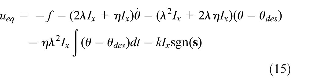
Figure 2 shows the block diagram of the active tilt SMC system.

Block diagram of the active tilt control system.
Simulation results and analyses
A numerical simulation is performed using MATLAB/Simulink to verify the performance of the designed controller. The parameters of the vehicle model are listed in Table 1.
Parameters of the steer–tilt model.

The vehicle is traveling in a straight line on a smooth road at a longitudinal speed of 80 km/h without considering the exogenous disturbances of vertical road vibration. The simulation time is 20 s, and the sampling time is 0.01 s. The simulation is performed while using 100% and 70% of the desired tilt angles as the control targets when the vehicle is given a step steer input. The vehicle is turned at t = 5 s, and the steering angle reaches its final value

Front wheel steering angle.
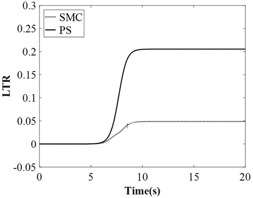
The response curves of the tilt or roll angle of the vehicle body are shown in Figure 4, where SMC, PS, and Desired represent the sliding mode active tilt control, PS, and desired tilt angle, respectively. The SMC can track the desired tilt angle well as its tilt angle overlaps the desired values. The tilt angle of the vehicle body with respect to active tilt control tilts inward to approximately 15°, which is opposite to the PS case. Figure 5 shows the response curve of the lateral acceleration experienced by passengers. The steady-state value of the lateral acceleration in PS is 3.3 m/s2. Meanwhile, in the SMC case, the lateral acceleration initially has a small fluctuation and then approaches zero as the torque generated by gravity offsets that by the centrifugal force. The SMC significantly improves lateral stability and ride comfort. The response curve of the LTR of the vehicle is shown in Figure 6. The LTR value of the PS system is 0.21. Meanwhile, the LTR value in the SMC case is similar to that of the lateral acceleration experienced by passengers. A small fluctuation initially occurs, and then the LTR value approaches zero. The active tilt control reduces the LTR, decreases the possibility of rollover, and can increase speed while cornering.

Roll or tilt angle of the vehicle body.

Perceived lateral acceleration.

Lateral load transfer rate (LTR).
Taking 100% of the desired tilt angle θdes as the control target
Figures 7 and 8 show the control forces of the left and right active suspensions, respectively. The control forces are still within the allowable limits as the force of each actuator is half the control force on each side after the control forces are decomposed in four suspension actuators. Figure 9 shows the time response curve of the vehicle yaw rate, and the vehicle slip angle response curve is shown in Figure 10. In Figure 9, Ideal denotes the ideal yaw rate,

Control force of the left suspension.
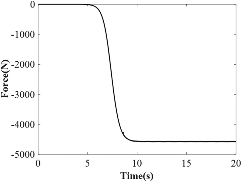
Control force of the right suspension.

Yaw rate.

Vehicle slip angle.

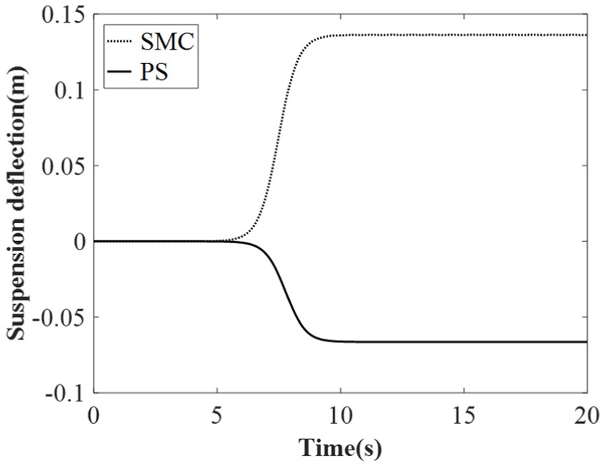
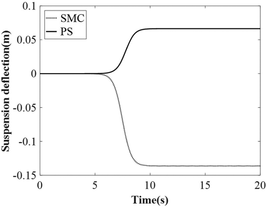
Left suspension deflection.

Right suspension deflection.
Taking 70% of the desired tilt angle θdes as the control target
The values of the desired tilt angle can be decreased properly within the acceptable range of LTR and perceived lateral acceleration experienced by passengers so as to reduce the actuator forces and energy consumption of the active suspension as well as reduce the suspension dynamic deflections. A total of 70% of the desired tilt angle is chosen as the active tilt control objective. Figure 13 shows the time response curve of the tilt or roll angle of the vehicle body. The tilt angle in SMC and the desired value overlap; thus, the tilt angle of the vehicle body in the active tilt control is consistent with the desired value. In total, 70% of the desired tilt angle, which is approximately 10°, is lower than that in the 100% of the desired tilt angle. Figure 14 shows the steady-state values of the lateral acceleration experienced by passengers. The lateral acceleration in the SMC is larger than the SMC’s acceleration in the 100% of the desired tilt angle case shown in Figure 5. However, the lateral acceleration in SMC, the amplitude of which is only 18% of the acceleration in PS, is still considerably less than that in PS. The steady-state values of the LTR are shown in Figure 15. The LTR in SMC is larger than that in the 100% of the desired tilt angle case shown in Figure 6. However, the LTR in SMC, the amplitude of which is only 25% of the LTR in PS, is still considerably less than that in PS.

Roll or tilt angle of the vehicle body.

Perceived lateral acceleration.
LTR.
The control forces of the left and right vehicle active suspensions are shown in Figures 16 and 17, respectively. The forces are reduced to approximately 20% compared with that in the 100% of the desired tilt angle.

Control force of the left suspension.

Control force of the right suspension.
Figures 18 and 19 show the time response curve of the yaw rate and the vehicle slip angle response curve, respectively. Compared with the yaw rate in PS, the yaw rate in SMC is closer to the one in the Ideal case. And the amplitude of the slip angle in SMC is much smaller than the one in PS. Therefore, the SMC can achieve better turning performances. Figures 20 and 21 show the time response of the suspension deflections. The values of suspension deflections in SMC are reduced to approximately 30% and are significantly lower than those in the 100% of the desired tilt angle, as shown in Figures 11 and 12.

Yaw rate.

Vehicle slip angle.
Left suspension deflection.
Right suspension deflection.
Conclusion
The proposed SMC for active suspension can actively tilt a vehicle inward to decrease the lateral acceleration experienced by passengers and LTR when the vehicle is steering, thereby improving handling stability, ride comfort, and traveling speed and preventing rollover effectively. In addition, the desired tilt angle and actuator force of the active suspension can be decreased according to the requirements of different driving conditions, thereby potentially reducing energy consumption.
Footnotes
Handling Editor: Muhammad Akhtar
Declaration of conflicting interests
The author(s) declared no potential conflicts of interest with respect to the research, authorship, and/or publication of this article.
Funding
The author(s) disclosed receipt of the following financial support for the research, authorship, and/or publication of this article: This work was funded by the “Summit of the Six Top Talents” Program of Jiangsu Province, China (grant no. JXQC-005), the Natural Science Foundation of Jiangsu Province (grant no. BK20181403), and the China Scholarship Council (CSC; file no. 201808320051).