
Abstract
Roller linear guides are key components in machine tool. The accuracy and efficiency of a machine toll are determined by the stiffness and friction torque of roller guide. This study proposes an improved design method for roller guide. The influences of the rollers profile on stiffness, stress distribution of roller linear guide are analyzed using finite element simulation. In this work, the design of the roller, slider, and the overall structure is modified. Moreover, experimental investigations on noise and sliding friction of roller linear guide are compared to validate the proposed design method. It seems that the proposed design can improve the dynamical performance of the roller linear guide.
Introduction
Roller linear guide has the advantages of high rigidity, high stability of accuracy, and stable operation compared to ball linear guide pair. It is widely used in high-speed numerical control (NC) machine and machining center. Figure 1 illustrates components of a roller linear guide which is researched in this article.
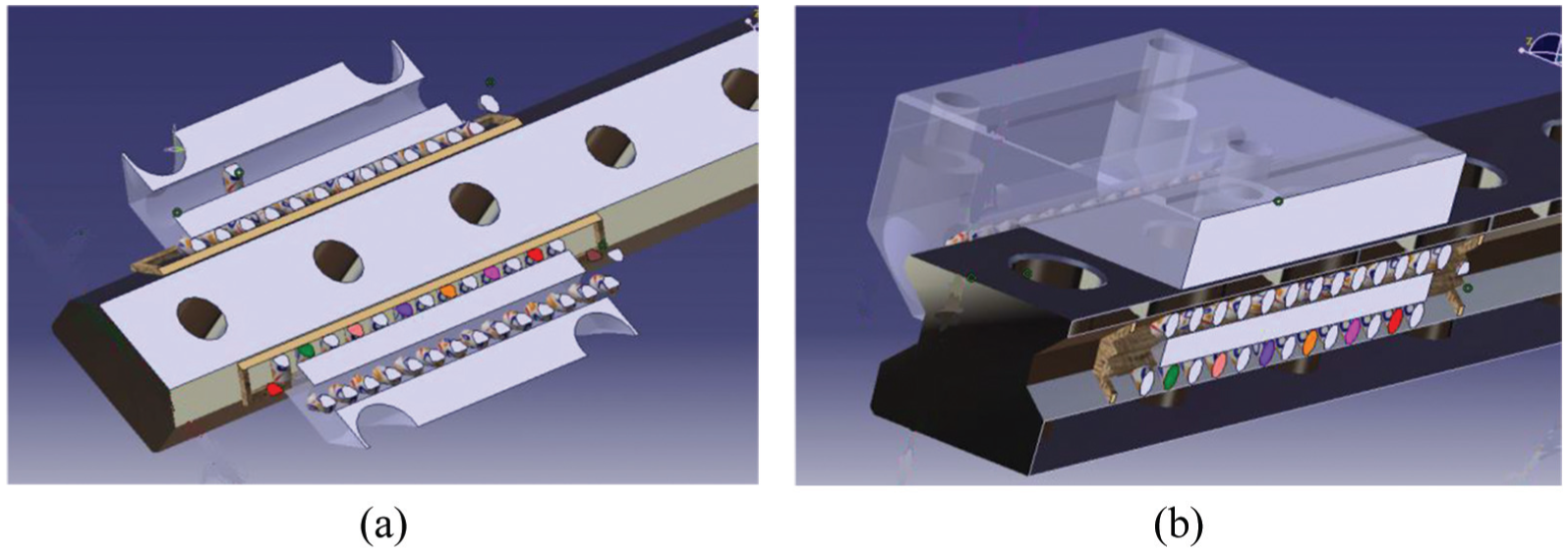
(a) Cross-sectional view of heavy-load roller linear guide and (b) side view of heavy-load roller linear guide.
As the roller recirculates between raceway and the reverser, its dynamic state changes dramatically. The roller in the raceway is preloaded, while it is free in the reverser. These changes lead to the collision and blockage of the roller at the exit and the entrance of the reverser, and leading to increase of friction resistance and the noise of the guide pair. 1 With the feeding speed of the roller linear guide increased to 80 m/min, the noise and friction of the roller guide become more serious issue. Analytical models for roller linear guide have been developed and improved by lots of researchers, from which the stress distribution and motions of roller can be evaluated to conduct the analysis of dynamics performance.2,3
Wang et al. 4 analyzed the stress of the contact area of the roller linear guide, and the contact stress distribution of cylindrical roller in roller linear guide based on finite element method. Liu 5 proposed a new modification theory of the roller based on the Johns–Gohar formula and analyzed the stress concentration phenomenon of the repaired roller using the finite element simulation. Liu et al. 6 analyzed the influence of the convex type of the roller on the contact stress distribution based on the finite element method and compares the advantages and disadvantages of all kinds of the convex type. However, the author did not take into account the impact of the slider and the overall layout of the roller linear guide on the bearing capacity, and there is no test to verify the correctness of the simulation results. Fujita et al. 7 investigated the relationship between frictional force of linear guide and slider oscillation by experiment. Ohta and Hayashi 8 studied the dynamic characteristics of linear rolling guide based on finite element simulation and researched the influence factors of ball noise in linear guide.
All the aforementioned studies commonly took finite element analysis as the tools to analyze static and dynamical performance of the roller linear guide. However, other dimensional factors such as the profile of the roller, roller rib and reverse groove were not involved. In an attempt to extend those works using both experimental and numerical sources, we developed a dynamic 3D finite element method (FEM) model corroborated by an experimental study and used it to determine the weak link of roller linear guide and verify the proposed method. Our approach aims at providing additional design method on improvement of roller linear guide dynamical performance.
Structural design
Stress analysis of the rolling body
According to the Hertz contact theory, it is easy to show the stress concentration during the contact between the linear roller and the raceway, which seriously affects the life of the contact pair. In order to eliminate the end of stress concentration from structural design, the stress of the rolling body is analyzed under the same load condition. The finite element model is as follows:
The modeling and calculations concerned a roller linear guide, type LZ45. In creating a physical model, we used information provided by the manufacturer’s official materials. The roller parameter is

(a) Contact stress distribution diagram of full convex roller and (b) contact stress distribution diagram of cylindrical roller.
The above analysis shows that the contact wear between roller and raceway is mainly due to the end of stress concentration. Therefore, the main task is to eliminate the stress concentration. It can be seen from the literature that many experts have only carried out the optimal design of the roller structure, and there is little research on the structural design of the reverse groove and roller rib. Based on the finite element simulation, the roller, reverse groove, and rib of the roller linear guide are optimized to improve the bearing capacity of the guide pair.
Influence of the full convex roller structure
Under the same load conditions, through the finite element simulation of the contact area, the size of the roller crowning arc is calculated at the minimum contact stress of the contact area. The variation range of arc size is
According to the above data, we can see that the minimum contact stress should be
Figure 3 shows the variation curve between the contact stress and roller arc. It can be seen from the analysis data that when the roller bearing the load, its displacement of the contact pair decreases with the increase of the roller arc. The larger the roller arc, the smaller the variation. When the roller arc is larger than 1000 mm, the change of the displacement is close to the constant value. As the roller linear guide is characterized by the large bearing capacity, the contact stress is taken as the objective function in the analysis of the linear guide, and the displacement is taken as the dependent variable.

The variation curve between contact stress and roller arc.
For the generatrix structure of the roller, the arc generatrix can eliminate the machining error of the raceway to a certain extent, and it has the function of adjusting the error. Compared with the cylindrical roller, the contact stiffness of the full convex roller is smaller, and the stiffness has little difference with the other types of roller under heavy load. The relieved end roller does not have the function of adjusting the error of the track, but compared with the cylindrical roller, both the light and the heavy load stiffness of the crowned profile roller is close to the cylindrical roller. This kind of structure not only solves the problem of stress concentration by optimizing design, but also keeps the rigidity of the roller linear guide to a large extent.
Influence of slider structure
Figure 4 is the cross-sectional view of LZ45 roller linear guide.
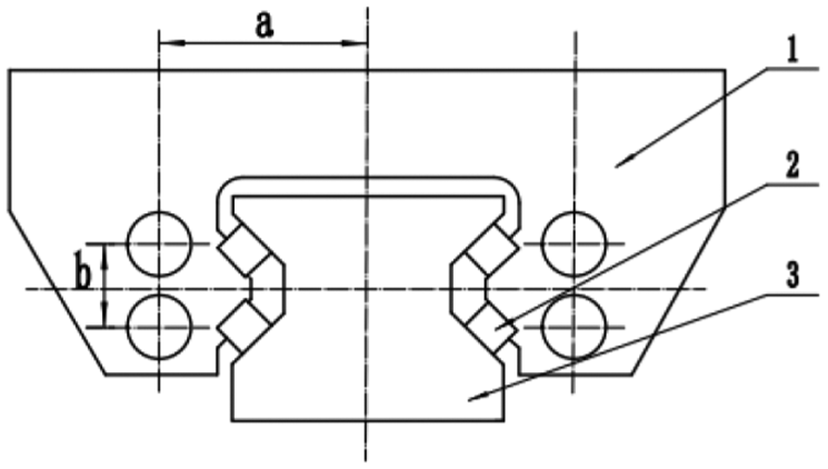
Cross-sectional view of LZ45 roller linear guide.
The high bearing behavior is the feature of roller linear guide. Under the high load condition, any small weak link of the bearing structure will be infinitely magnified, thus leading to the emergence of major problems. The finite element analysis software is used to analyze and optimize the slider structure of the roller linear guide.
The modeling and calculations concerned a roller linear guide, type LZ45. The dimension parameters of roller linear guide are shown in Figure 5 and Table 1. The linear guide is meshed by using PLANE13 element, and the finite element model obtained is shown in Figure 6. According to the actual working condition of the roller linear guide, nodes on the rail-mounting surface are set to be fixed. The vertical downward and upward load of 20 kN is applied to the upper surface of the slider.
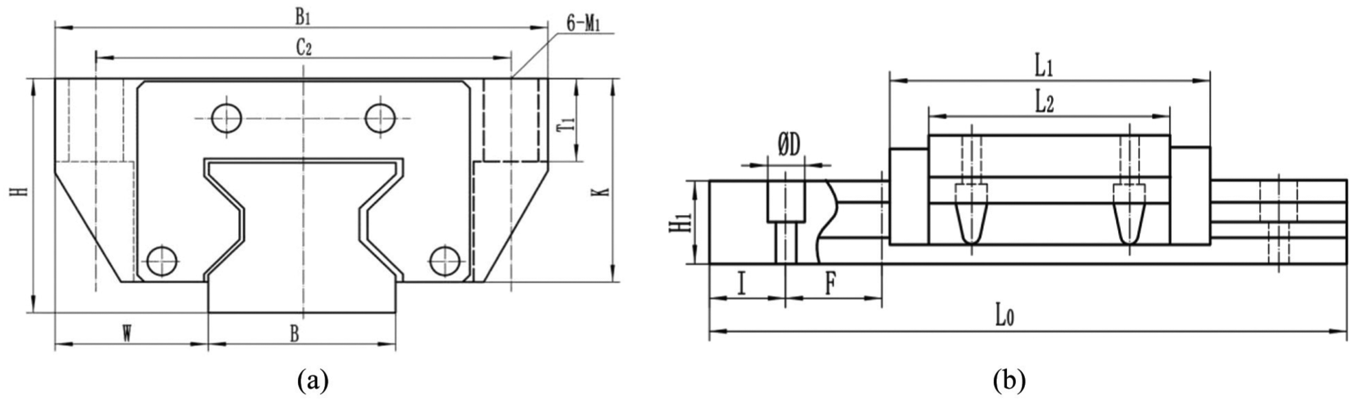
Structure diagram of roller linear guide: (a) main view and (b) side view.
Dimension parameters of roller linear guide of simulation setup.


Finite element model.
Influence of the reverse groove
According to the stress distribution of the slider under the loading condition in Figure 7, it can be seen that the distance of the reverse groove, the reverse groove, and the distance of cavity straight groove are the main parts of the stress concentration. According to the objective and plan, increasing the load-carrying properties of the raceway is the most concern, that is, the raceway is the largest part of the stress rather than any other parts. If there appeared stress concentration in other parts, it should be eliminated from structural design.

(a) The stress distribution of the slider bears vertical downward load and (b) the stress distribution of the slider bears vertical upward load.
The stress distribution can be examined after changed the size a and size b in Figure 4. It can be seen from the stress distribution graph that the slider structure of LZ45 roller linear guide has obvious weak stress links from the aspects of the design. In order to eliminate the weak link’s influence on LZ45’s load-capacity, the size a and size b are changed appropriately. It can be seen from Figure 8 that most of the bearing capacity is passed through the structure between the reverse groove and the cavity straight groove. Therefore, the structural strength of this part should be increased as much as possible in the structure design. Because it involves other structural designs, so there is only trend analysis here, and no specific definition of size.
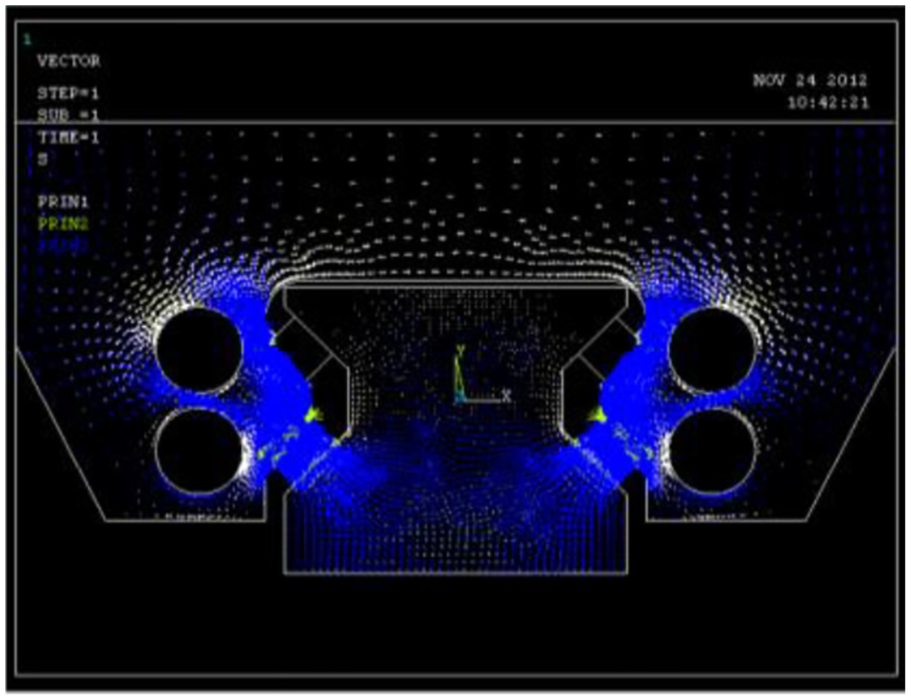
The graph of tress vector of sliding block under the load condition.
Influence of the roller rib
The role of the roller rib of the roller linear guide is to guide the rolling direction of the roller, and it does not bear forces or very little under the normal conditions. But the roller rib may be squeezed in some abnormal conditions, as shown in Figure 9.

The structural diagram of contact between roller and track baffle.
The roller face is in close contact with the vertical rib, in which case the contact area between the roller rib and the roller face is larger. If the roller has the extrusion force between the rib and the roller face for some unknown reason, the frictional force will influence the movement of the roller even make it tilt. At the same time, due to the tight contact, it is hard to store the lubricating oil and lead to the bad contact condition, which affects the service life.
Through the analysis of the force of the slider, it is found that the position of the bead hole has great influence on the bearing capacity of the slider, which can be obtained from the distribution diagram of the bearing stress. The larger distance between the reverse groove and the cavity groove, the smaller deformation of the bearing, the better performance. This kind of variation trend is semi-open, so it should consider other related size first and make a choice later. The role of the roller rib is to guide the rolling direction of the roller. From the above analysis, the contact area between the roller face and the rib should be decreased, as well as the sliding friction. This friction is not obvious under the low-speed and the low load conditions of the guide rail, but when the roller linear guide is running at high speed and high pressure, it will have a great influence on the movement temperature and noise of the guide rail.
Result and analysis
The structure and main function of the test bench
The structure of the test bench is shown in Figure 10. It is mainly used to detect the comprehensive performance and accuracy index of the linear guide pair with less than or equal to 4 m long and 35–65 specifications. It included the following parts: friction, noise, temperature, acceleration, vibration, motion accuracy, and so on.

The structure diagram of linear guide rail comprehensive performance test bench.
The test bench is driven by a linear motor and it tests two linear guides at the same time. The linear motor is installed on the bottom of the sliding table, and the sliding table is driven by a linear motor to do the round-trip movement on the high-speed mute guide rail. The weighing sensor is installed on the slider of the tested guide rail, and a floating connection between the sliding table and the tested slider is adopted to measure the performance information of the slider in real time.
Analysis of test results
The tested LZ45 roller linear guide is installed on both sides of the high-speed test bed driven by the linear motor, as shown in Figure 11; the left and right sliders are connected to the force sensor. The test system collects output signals of the sensor, and the test report is shown in Figure 12.

Roller linear guide to install test photos on the test bench.
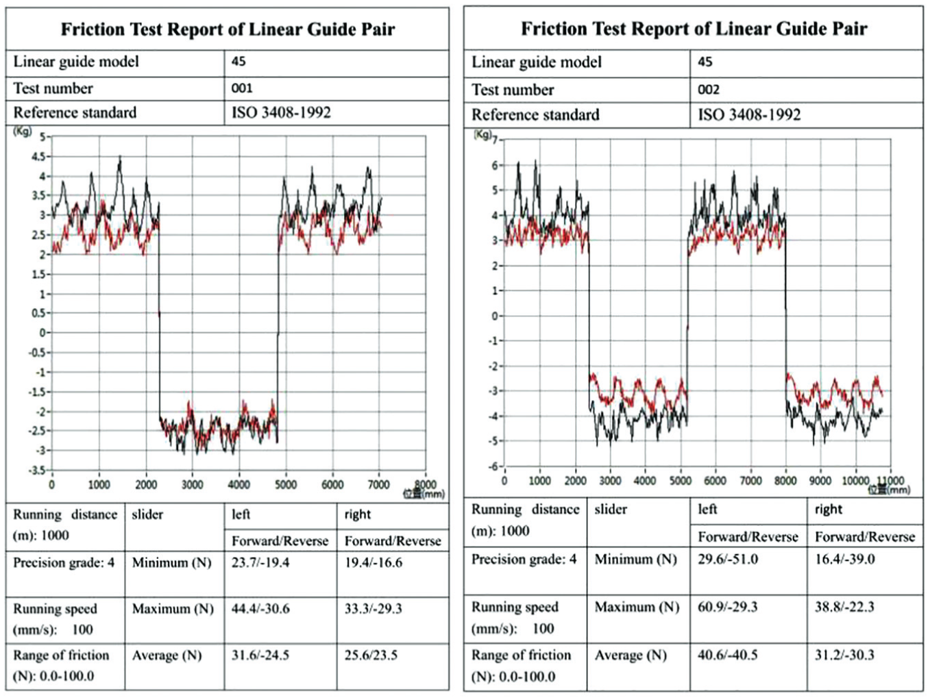
Test results of friction force of LZ45 roller linear guide slider.
It can be seen from the test results that after the optimum structural design, the average frictional force of the left sliding block decreases from 40.5 to 24.5 N, and the right slider decreases from 30.3 to 23.5 N, and the sliding block movement is more smoothly. The noise measurement of sliding block at high speed is shown in Table 2, and the average noise decreases by 2 dB.
The measurement results of the motion noise of roller linear guide at different speeds.

The test results of friction and noise show that the friction and noise are obviously reduced by optimizing the design of the roller, slider, and the rib of the roller linear guide. It shows that the slider movement is more fluent and the bearing capacity of the roller linear guide is improved.
Conclusion
The modified roller structure can not only eliminate the stress concentration in the end of the roller and the raceway, but also maintain the rigidity of the guide pair.
The influence of the weak link of the slider on the bearing capacity can be eliminated by reasonable design of the position of the reverse groove. The sliding friction can be decreased by reducing the contact area between the roller end and the rib.
The test results show that the friction and noise are obviously reduced by optimizing the design of the roller, slider, and the rib of the roller linear guide. It shows that the slider movement is more fluent and the bearing capacity of the roller linear guide is improved.
Footnotes
Acknowledgements
The authors would like to thank BTP for their assistance in conducting this research.
Handling Editor: Zengtao Chen
Declaration of conflicting interests
The author(s) declared no potential conflicts of interest with respect to the research, authorship, and/or publication of this article.
Funding
The author(s) disclosed receipt of the following financial support for the research, authorship, and/or publication of this article: This study was financially supported by the Science Technology Development Program of Shandong Province (Project #2017GGX30131,# J17KA035).