
Abstract
The vaned diffuser has a significant impact on the performance and operating range of a centrifugal compressor stage, and multi-row vaned diffusers are applied to improve the compressor characteristics in this article. In order to validate the effectiveness of the present calculation method, the calculation results of the centrifugal compressor with the conventional diffuser have been verified by the experimental data. The simulation results reveal that, compared with the original model at design point, the isentropic efficiency increases by 2.8% and 4.1%, and the total pressure ratio increases by 1.9% and 3.4%, for the compressor stage with the two-row vaned diffuser and the three-row vaned diffuser, respectively. The models with multi-row vaned diffusers also give higher static pressure recovery coefficient and lower total pressure loss coefficient. A pressure gradient formed on vane suction surface near vane leading edge develops the flow separation in the conventional diffuser. The pressure gradient thus causes the secondary flow from hub to shroud on vane suction surface, aggravating the separation in the rear part of the conventional diffuser. The analysis of flow characteristics in diffuser passages also shows that using multi-row vaned diffusers can alleviate flow separation appearing in the diffuser passages.
Introduction
Centrifugal compressors have extensive applications in process industries. The primary flowthrough components of a centrifugal compressor stage usually comprise an impeller and a diffuser, and a bend and a return channel. An impeller is the unique moving component which transforms the mechanical energy of moving solids into kinetic, potential (pressure), and thermal energies of moving fluid. Since a large portion of the energy input to the working fluid still remains in the form of kinetic energy at the exit of the impeller, a diffuser is usually fixed downstream of the impeller outlet to recover the static pressure of the working fluid. After that, a bend and a return channel are used for admission of the working fluid to the subsequent stage. Because the space for improving the efficiency of the impeller is rather limited with the implementation of various advanced design methods, the improvement of centrifugal compressor stage efficiency now is mainly achieved via modification of the stationary components, especially the diffuser.
Different types of diffusers have been invented and designed over the past decades to improve the characteristics of the centrifugal compressor stage. The vaneless diffuser is widely applied for its wide operating range and low cost of manufacture. Jaatinen-Värri et al. 1 studied seven different vaneless diffuser designs, varying only in diffuser width, for a centrifugal compressor experimentally. Three of the narrowed diffusers had the width reduced (pinch) from the hub and shroud evenly, while the three others only from the shroud. The results revealed that the pinch improved the compressor stage and the impeller performance but deteriorated the diffuser performance. The pinch in the shroud was more beneficial than that from the hub and the shroud. Hazby et al. 2 investigated the evolution of the flow in the vaneless diffuser using viscous calculations and compared the flow patterns with the detailed laser Doppler anemometry (LDA) and probe measurements at different operating conditions. The results revealed that vortical flow features developed near the diffuser shroud at high flow coefficients, and the flow separation was generated by strong pressure variations downstream of the blade trailing edge and disappeared at low flow coefficients. Compared with the vaneless diffuser, the conventional vaned diffuser is known to have higher diffuser efficiency at design point with a compact size, but its stable operation range becomes narrower. Therefore, the requirement for high efficiency and compact size has led to widespread applications of different vaned diffusers in centrifugal compressors. Many previously published papers3–7 on diffusers are focused on the influence of vane shapes on performance characteristics. Liu and Xu 8 presented a computational investigation of the flow field in a high-speed centrifugal compressor with a backswept unshrouded impeller and vane diffuser. A numerical simulation of the compressor with eight kinds of non-dimensional hub vane height h/b was conducted to study the influence of the diffuser hub vane height on the flow characteristics. Issac et al. 9 experimentally studied the effect of diffuser vane height that varied from 0.2 to 0.9 times the diffuser width and vane position by fixing the partial vanes to the hub, shroud, or hub and shroud on the performance of a low-speed centrifugal compressor. It was found that there was an optimum height of 0.3 times the diffuser width for the diffuser vane height. Meanwhile, when partial vanes were fixed on the hub and shroud, the compressor performance was improved substantially compared with that fixed on the hub or shroud. Other studies involve the influence of the high-speed impellers and the low-solidity diffusers on compressor stage performances. For example, Grates et al. 10 investigated the flow inside a transonic centrifugal compressor stage with a pipe-diffuser by utilizing numerical simulation in combination with the experimental data. Their results showed that the specific geometry of the pipe-diffuser had an obvious positive impact on the characteristics of the compressor stage. Engeda11,12 carried out parametric studies on low-solidity diffuser composed of simple flat plate vanes by varying the diffuser solidity. The results showed that the operating range became wider with reduced solidities while static pressure recovery was improved with increased solidity. Reddy et al. 13 investigated the effect of setting angle of a low-solidity vaned diffuser on the performance of a centrifugal compressor stage. Because the flow into the diffuser is usually distorted by the impeller wake, the aerodynamic design of the vaned diffuser should take the influence of the impeller into account to achieve a higher diffuser performance. Experimental investigations on the rotor–stator interaction for centrifugal compressors were performed by Gallier et al., 14 which showed the substantial interaction due to the existence of the downstream diffuser vanes. Ziegler et al.15,16 presented experimental investigations on the effect of the radial gap between impeller exit and diffuser vane inlet on the impeller–diffuser interaction and found that a relative smaller radial gap was leading to a notable reduction of the wake region at impeller exit, which obtained a more uniform flow field at the exit of vaned diffuser and a higher diffuser static pressure recovery. Tan and colleagues17–19 presented unsteady investigations on a centrifugal pump by using a numerical framework combining the renormalization group k–ε turbulence model. In addition, the tandem or multi-row cascades have obvious influence on the flow of the compressor stage compared with traditional cascades. While the tandem impeller has attracted wide attention for its benefits over conventional impeller, 20 the application and research of tandem or multi-row cascades used in diffusers are still rather limited.
The vaned diffuser has the advantage of a higher pressure recovery coefficient (RC) and a higher efficiency in a compact space compared with the vaneless diffuser. The application of vaned diffuser in a centrifugal compressor often leads to a narrower high efficiency range because of the separation at the latter part of the vane. To alleviate the separation and to improve the flow situation in the vaned diffuser passages, multi-row vaned diffusers are applied in a centrifugal compressor stage that consisted of impeller and diffuser in this study. The remainder of this article is organized as follows. Section “Physical model and computational method” introduces the physical model and computational method of the compressor stage and proposes a modification on the vaned diffuser. Section “Flow analysis and discussion” presents and discusses the improvements on the performances of the compressor stage and on the characteristics of the flow field. Section “Conclusion” summarizes this article with some main conclusions.
Physical model and computational method
Centrifugal compressor stage
The centrifugal compressor stage in this study is from a four-stage air separation compressor with a design air mass flow rate of 40.5 kg/s at a design speed of 7664 r/min. The shrouded impeller contains 16 blades with 55° backswept and the original vaned diffuser consists of 24 circular arc vanes. A vaneless space downstream of the impeller is gently contracted to give a pinch for improving flow stability. The meridional view of the centrifugal compressor stage is shown in Figure 1. Figure 2 presents the model of the impeller and diffuser. Table 1 summarizes the details of the main geometry of the centrifugal compressor flowthrough components.

Meridional view of centrifugal compressor stage.

Model of the impeller and diffuser.
Specifications of the compressor components.

In the vaned diffuser, the vaneless space upstream of the vane leading edge and downstream of the vane trailing edge may influence the flow condition in the vaned diffuser. The velocity triangle and flow path in the vaneless diffuser are shown in Figure 3. The radial velocity follows the continuity equation

Therefore, for an inviscid and incompressible flow in a parallel-walled diffuser,
This means that for inviscid and incompressible flow in a parallel-walled diffuser, the streamlines are logarithmic spirals. Thus, it flows over a longer distance in the diffuser passage with a larger radius position, which possibly causes a large friction loss in the diffuser.

Schematic view of the vaneless diffuser.
Therefore, the position of vaneless space in diffuser passage could have a significant impact on the performances of compressor stage and characteristics of flow field. Besides, in conventional vaned diffuser passages of a centrifugal compressor stage, the static pressure rises rapidly with an increasing radius along the front part of the diffuser blade, while in the rear part it rises slightly. The flow separation in diffuser passages is more inclined to occur near the trailing edge of the diffuser blade due to a large diffusion effect.
In order to alleviate the separation in the vaned diffuser passage and to reduce the friction loss in the vaneless space of the vaned diffuser passage, multi-row vaned diffusers are applied in the centrifugal compressor stage. The multi-row vaned diffusers are obtained via cutting the conventional diffuser vane into several pieces and separating them into different rows in the diffuser passage. By contrast with the tandem vaned diffusers that the vanes are close or even overlapped in the radial direction, the multi-row vaned diffusers have a relatively large gap between the rows in the radial direction. In this article, the original diffuser vane is cut into two identical parts as the vanes of two-row vaned diffuser. The first row is located at the same position as the first half of the conventional diffuser. The second row is placed, according to the geometric shape of the conventional diffuser, downstream of the first row. The three-row vaned diffuser is obtained from the two-row vaned diffuser by cutting the second row into two identical pieces, and the third row is placed downstream of the second row. The schematic view of the two-row and three-row vaned diffuser is shown in Figure 4. Table 2 summarizes the dimensions of multi-row vaned diffuser. The object of the research is to investigate the effect of multi-row vaned diffusers on the performances and flow fields of the centrifugal compressor stage.
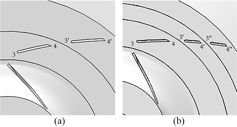
Schematic view of multi-row vaned diffuser: (a) two-row vaned diffuser and (b) three-row vaned diffuser.
Dimensions of multi-row vaned diffuser.

Grid generation and computation method
ANSYS CFX 15.0 is employed in this study. In grid generation, the structured mesh of the impeller and diffuser is generated in two domains to improve the quality of the grid efficiently. Both domains are in combination to generate a single computational fluid dynamic domain with the frozen rotor treatment at the rotational/stationary interface. The grid number is about 396,000 for a single passage in the impeller domain, and the grid number is about 401,000 for a single passage in the conventional diffuser domain. The multi-block structured grid is also employed to mesh both the impeller and the diffuser. For the two-row vaned diffuser, the grid number is about 194,000 for the first row and 196,000 for the second row. The grid number of the three-row vaned diffuser is 199,000, 99,000, and 102,000 from the first row to the third. Block-structured grids are used and shown in Figure 5.

Grid of compressor stage: (a) the impeller, (b) one passage of the impeller, and (c) computational domain of the compressor stage.
The wall distance of the first layer of the near-wall grid is set to 0.002 mm to guarantee that the boundary layer resolution is sufficiently fine for the turbulence model. The distribution of Y plus on the surface of blade passage obtained from the flow simulation is shown in Figure 6, which indicates that the length scale of the near-wall meshes relatively satisfies the essential requirement for simulating the flow inside the boundary layers.

Distribution of Y plus of the compressor stage passage.
The mesh quality meets the requirement for reliable simulations with the maximum aspect ratio and expansion ratio and the minimum orthogonality in the suggested range. Gird independence analysis is conducted with the wall distance of the first layer near-wall grid, mesh topology, and other factors of the case kept unchanged. Four different meshes shown in Table 3 were used in order to investigate the mesh dependency of the numerical model. The efficiency and total pressure ratio decrease along with the increase in the grid number. However, when the grid number varies from Scheme 3 to 4, the performance of the compressor stage decreases very little, but the consumption of the computing resources increases rapidly. Thus, Scheme 3 in which the grid number is approximately 0.8 million is selected.
Grid count for the grid dependency study.

As shown in Figure 1, the numerical simulations of the compressible flow in a whole domain from computational fluid dynamics (CFD) inlet boundary to CFD exit boundary have been carried out and analyzed using the finite volume method with four-step Runge–Kutta time integration scheme and the second/fourth-order artificial dissipation damping. The three-dimensional (3D) turbulent internal flow is calculated using the CFD code of Ansys-CFX together with the k–ω turbulence equation model. Three-dimensional steady compressible Reynolds-average Navier–Stokes equations are solved using a finite volume scheme, and spatial discretization is done with a central scheme. Total temperature and pressure together with the uniform velocity distribution are implemented as inlet boundary conditions; mass flow is set as the outlet boundary condition. In computation, the impeller and diffuser domains are combined with the so-called Frozen Rotor interaction scheme for the interface treatment, which means the flow in the impeller is calculated in relative coordinates and the flow quantities are transformed to the inlet of the diffuser over the interface without varying the relative position of the impeller and the diffuser. The interface is located approximately in the middle between the impeller outlet and the diffuser inlet. No-slip and impermeability conditions are imposed on the impeller blade surfaces.
Computation method validation
To obtain the experimental isentropic efficiency and total pressure ratio, the parameters measured during the performance test include total temperature, total and static pressure at the inlet and outlet of the compressor stage, mass flow rate, atmospheric pressure, temperature, and humidity according to the code ASME PTC-10.
In order to validate the effectiveness of the present calculation method, the calculation results of the centrifugal compressor with the conventional diffuser are compared with the experimental data. Figure 7 shows the comparison of the calculation results and experimental data. Although both the calculated pressure ratio and isentropic efficiency are slightly higher than the experimental measurement in the whole flow range, the maximum errors of the pressure ratio and efficiency are not more than 1.1%. The discrepancies are possibly due to the influence of leakage and friction loss, which is not considered in the calculation. It can be concluded that the calculation results have a good consistency with the experimental data within the allowable error range. From the comparison in Figure 7, it can be regarded that the calculation method used in this article can be effectively applied to the analysis of aerodynamic performances of a centrifugal compressor stage.

Comparison of measured and calculated results: (a) the isentropic efficiency and (b) the total pressure ratio.
Flow analysis and discussion
The impeller used in the stage with the multi-row vaned diffusers is the same as that in the compressor with the conventional diffuser. A comparison of the overall aerodynamic performance for the compressor stage with the conventional diffuser and that with the two-row vaned diffuser is presented in Figure 8. It can be seen that compared with the original model, the efficiency and the pressure ratio increase by 2.8% and 1.9% for the compressor stage with the two-row vaned diffuser at a design flow rate (Q) of 40.5 kg/s, respectively. Under 85% Q, the compressor stage with the two-row vaned diffuser gives higher efficiency and pressure ratio than the original model, while the efficiency and pressure ratio for the two-row vaned diffuser are lower than those for the conventional diffuser near 120% Q.

Performance curves of compressors with conventional and two-row diffusers: (a) the efficiency and (b) the total pressure ratio.
In the diffuser of a compressor stage, static pressure RC and total pressure loss coefficient (LC) are important parameters for describing the characteristics of diffuser, and they are defined as
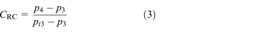

In the above expressions, pt3 and pt4 represent the total pressure of the diffuser inlet and outlet, and p3 and p4 represent the static pressure of the diffuser inlet and outlet. The RC and LC of the two different diffusers under the design flow rate are listed in Table 4, respectively. Compared with the conventional diffuser, the RC increases by 7.8% for the two-row vaned diffuser, while the LC approximately decreases by 15.6%. According to Table 4, we can observe that the two-row vaned diffuser has a better performance than the conventional diffuser under design condition.
Two-row diffuser characteristics under the design condition.

Figure 9 presents 3D streamlines in the diffuser passage. It can be seen that a visible separation occurred near the latter part of the diffuser vane around the hub of the passage.

Three-dimensional streamlines in diffuser passage.
The computed velocity contour and streamline distributions at 10%, 50%, and 90% span heights of the conventional diffuser and the two-row vaned diffuser are compared in Figures 10 and 11. For the conventional diffuser, a visible separation occurred near the trailing edge of the diffuser vane at 10% span height, while at 50% and 90% span heights, no obvious flow separation region appears in the conventional diffuser passage. For the two-row vaned diffuser, although the flow separation also occurs at 10% span height, the region of separation located at the tail of the second-row vane is much smaller than that of the conventional diffuser. Comparing Figure 10 with Figure 11, it can be observed that in the two-row vaned diffuser, the separation flow has been remedied evidently. The flows along both sides of the first row of the two-row vaned diffuser mix together in the space between diffuser vane rows, which reduces the tendency of flow separation near the rear part of the diffuser passage, thus leading to the rise of efficiency and pressure ratio of the compressor stage.

Velocity contours and streamlines at different span heights of conventional diffuser at design flow rate: (a) 10% span, (b) 50% span, and (c) 90% span.

Velocity contours and streamlines at different span heights of the two-row diffuser at design flow rate: (a) 10% span, (b) 50% span, and (c) 90% span.
Figures 12 and 13 show the entropy distribution at 10% span, 50% span, and 90% span of the conventional diffuser and the two-row vaned diffuser. It can be seen that the loss at 10% span is higher than that at 90% span. Compared with the two-row vaned diffuser, a zone with higher loss exists near the trailing edge of the diffuser vane at 10% span height of the conventional diffuser. The results drawn from Figures 12 and 13 are basically in accordance with the flow field shown in Figures 10 and 11.

Entropy distribution at different span heights of the conventional diffuser at design flow rate: (a) 10% span, (b) 50% span, and (c) 90% span.

Entropy distribution at different span heights of the two-row diffuser at design flow rate: (a) 10% span, (b) 50% span, and (c) 90% span.
Figures 14 and 15 show the static pressure distributions on diffuser vane surfaces near hub and shroud for both conventional vaned diffuser and two-row vaned diffuser at design flow rate. The static pressure along the diffuser vane surface is normalized by the static pressure of each diffuser vane inlet. It can be observed in Figure 14 that a pressure deviation of hub and shroud appears on the vane suction surface just after local accelerated flow near vane leading edge in the conventional vaned diffuser. A pressure gradient formed by the deviation in the suction surface of conventional diffuser then causes secondary flow; thereby, the phenomenon of flow separation in the diffuser passage gets worse. In Figure 15(a), the static pressure near hub and shroud is rather close for both pressure surface and suction surface, while the deviation of the pressure appears at the tail of second row in the two-row vaned diffuser in Figure 15(b). Compared with the deviation in the conventional diffuser, the intensity is obviously less in the two-row diffuser, which also causes mild separation in the diffuser passages. This also explains the compressor performance shown in Figure 8.

Static pressure distributions around diffuser vanes on both near hub and shroud of the conventional diffuser.

Static pressure distributions around diffuser vanes on both near hub and shroud of the two-row diffuser: (a) the first row and (b) the second row.
From the above analysis, the performances and characteristics of the centrifugal compressor have been improved under stable operation range using the two-row vaned diffuser. Compared with the evident flow separation in the conventional diffuser, the flow separation region is mainly located in the latter part of second row of the two-row diffuser passage. Although it has gained obvious improvements of flow fields in the two-row diffuser passage, there is still space for a further modification of performances and characteristics. The three-row vaned diffuser is obtained from the two-row vaned diffuser by cutting the second row into two identical pieces, and the third row is placed downstream of the second row, as shown in Figure 4.
A comparison of the overall aerodynamic performance between the compressor stage with the two-row vaned diffuser and that with the three-row vaned diffuser is presented in Figure 16. It can be seen that compared with the two-row diffuser at design flow rate (40.5 kg/s), the isotropic efficiency increases by 1.3%, and the pressure ratio increases by 1.5% for the compressor with the three-row vaned diffuser. Within the whole operation range, the compressor stage with the three-row vaned diffuser gives higher efficiency and pressure ratio than that with the two-row diffuser. Moreover, the compressor with the three-row vaned diffuser has a wider flow range, which restrains the surge toward small flow rate.

Performance curves of compressors with conventional and multi-row diffusers: (a) the efficiency and (b) the total pressure ratio.
From Figure 16, it can also be observed that the efficiency increases by 2.8% and 4.1%, and the pressure ratio increases by 1.9% and 3.4% for the compressor with the two-row vaned diffuser and the three-row vaned diffuser at design point, respectively, in comparison with that of the original model. Under 85% Q, the efficiency and pressure ratio of the compressor stage with multi-row diffusers are higher than those with conventional diffuser, while the efficiency and pressure ratio of the compressor stage with different diffusers are rather close under 120% Q. Meanwhile, it gives a wider operation range of the compressor stage with multi-row vaned diffusers, extending the surge point toward small flow rate.
The RC and LC of the two different diffusers under design flow rate are listed in Table 5. Compared with the two-row diffuser, the RC increases by 3.7% for the three-row vaned diffuser, while the LC approximately decreases by 9.3%. According to Tables 4 and 5, we can see that the multi-row vaned diffusers have a better performance than the conventional diffuser under the design condition.
Three-row diffuser characteristics under the design condition.

Figures 17 and 18 show the comparison of the static pressure RC and total pressure LC for the three different diffusers. The case of conventional vaned diffuser shows both poor RC and LC performance due to flow separation under 85% Q and near-design condition, compared with those of the multi-row vaned diffusers. However, under 120% Q, the two-row diffuser does not give good RC and LC, or even get worse than conventional diffuser. The results drawn from Figures 17 and 18 are basically in accordance with the compressor performance shown in Figures 8 and 16.
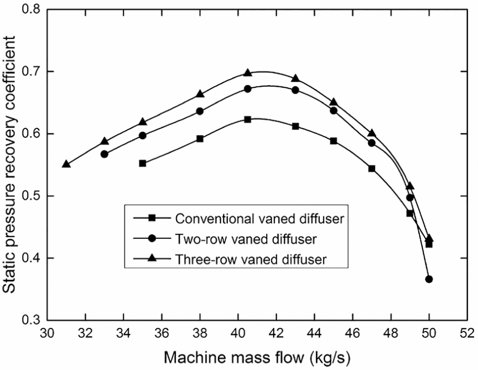
Static pressure recovery coefficient.

Total pressure loss coefficient.
The velocity contour and streamline distributions at 10%, 50%, and 90% span heights of the three-row vaned diffusers are presented in Figure 19. For the three different span heights of the diffuser, no obvious flow separation region appears in the diffuser passage. Comparing Figure 19 with Figures 10 and 11, it can be observed that in the multi-row diffusers, the separation flow in diffuser passage is remedied evidently. The two-row diffuser can effectively suppress the separation in the latter part of conventional diffuser passages, leaving some minor separation around the tail of the second row in the two-row diffuser passages, while there is few visible separation flow in the three-row diffuser passages. The reduction of separation region at the rear part of the multi-row diffusers is due to the energy input of the high-speed main flow. The flows along both sides of the vane mix together in the space between the multi-row vanes, which reduces the tendency of flow separation at the rear part of the diffuser, thus leading to the rise of efficiency and pressure ratio of the compressor stage. The results drawn from Figures 10, 11, and 19 can also explain the compressor performance at design flow rate shown in Figures 8 and 16.

Velocity contours and streamlines at different span heights of the three-row diffuser at design flow rate: (a) 10% span, (b) 50% span, and (c) 90% span.
Figure 20 shows the static pressure distributions on diffuser vane surfaces near hub and shroud for the three-row vaned diffuser at design flow rate. The static pressure is normalized by the static pressure at each diffuser vane inlet. From Figure 20(a)–(c), it can be seen that the static pressure near hub and shroud is close for both pressure surface and suction surface. Comparing Figures 14, 15, and 20, the pressure gradient formed on vane suction surface just after local accelerated flow near vane leading edge causing secondary flow develops flow separation in the conventional diffuser, while the accordance of the static pressure near hub and shroud in multi-row diffusers alleviates the separation in the diffuser passage, and thus there is no evident flow separation in the three-row diffuser passages.

Static pressure distributions around diffuser vanes on both near hub and shroud of the three-row diffuser: (a) the first row, (b) the second row, and (c) the third row.
Figures 21 and 22 show the velocity contour and streamline distributions at 50% span height of different diffusers under small and large flow rate. Under 85% Q, the multi-row diffusers still show no flow separation, while the flow separation region appears in the latter part of the conventional diffuser vane surface. Under 120% Q, no obvious flow separation region appears at 50% span height for the conventional and three-row vaned diffusers, and slight separation occurs at the trailing edge of the second row of diffuser vane. The results can also explain the compressor performance shown in Figures 8 and 16.

Velocity contours and streamlines of different diffusers at 50% span height under 85% Q: (a) conventional diffuser, (b) two-row diffuser, and (c) three-row diffuser.

Velocity contours and streamlines of different diffusers at 50% span height under 120% Q: (a) conventional diffuser, (b) two-row diffuser, and (c) three-row diffuser.
In general, the centrifugal compressor with multi-row vaned diffusers has evidently improved the characteristics of the flow field and the performances in the stable operating range, giving higher RC and lower LC in the diffuser.
Conclusion
Multi-row vaned diffusers are proposed to improve the performances of the compressor stage in this article, and the flow field characteristics in multi-row vaned diffusers are investigated using numerical simulations. The main conclusions can be drawn as follows:
The computed results and detailed analysis show that the efficiency increases by 2.8% and 4.1%, and the pressure ratio increases by 1.9% and 3.4% for the compressor with two-row vaned diffuser and three-row vaned diffuser at design point, respectively, in comparison with that of the original model. Under 85% Q, the efficiency and pressure ratio of the compressor stage with multi-row diffusers are higher than those with conventional diffuser, while the efficiency and pressure ratio of the compressor stage with different diffusers are rather close under 120% Q. In general, the performances and flow fields have improved in the normal operating ranges around design flow rate in the centrifugal compressor stage with multi-row vaned diffusers.
Compared with conventional diffuser, the multi-row vaned diffusers including two-row and three-row vaned diffuser have higher RC and lower LC. This demonstrates that the cases of multi-row vaned diffusers give good RC and LC, reducing the loss in diffuser passage and improving the flow situation.
In the compressor with multi-row vaned diffusers, the flow separation in the flow passages of diffuser is apparently remedied at design flow rate, compared with that in the conventional diffuser. This is probably due to the energy input from the high-speed fluid to the low-speed fluid at the space between the rows of vaned diffuser. The mixed flow is less inclined to separate in the diffuser, which would reduce the separation near the vanes and lead to the improvement in the performance of the compressor stage.
A pressure gradient formed on vane suction surface near vane leading edge develops the flow separation in the conventional diffuser. The pressure gradient thus causes the secondary flow from hub to shroud on vane suction surface, aggravating the separation in the rear part of the conventional diffuser. The multi-row vaned diffusers can alleviate the pressure gradient by contrast with that in the conventional diffuser, reducing the influence of the secondary flow and improving the flow field characteristics.
This is a preliminary investigation on the multi-row diffusers, and more research is needed on the influencing factors, such as the relative circumferential position, radial gap between rows, and ratio of chord length.
Footnotes
Handling Editor: Mustafa Canakci
Declaration of conflicting interests
The author(s) declared no potential conflicts of interest with respect to the research, authorship, and/or publication of this article.
Funding
The author(s) disclosed receipt of the following financial support for the research, authorship, and/or publication of this article: This study was supported by the National Natural Science Foundation of China (grant no. 51876158).