
Abstract
Hydrostatic guides or bearings are very important crucial components in precision mechanical system. First, the article selects the structural parameters of the standard design film restrictor with regard to hydrostatic bearing. Moreover, using COMSOL, the article performs the fluid–structure interaction analysis of the diaphragm to obtain pressure and stress field distribution, and the deformation of diaphragm in membrane restrictors. Then, fluid resistance and other related properties of the membrane restrictors are obtained, and the related parameters including oil pressure, restrictor gap, membrane thickness, and membrane restrictors to perform feedback action of different oils are explored. Finally, the simulation results and experimental measurements are compared to verify their feasibility. In this study, an oil pressure of 10 bar induced deformation of the membrane with consistent trend; however, oil pressures of 30 and 50 bar induced large error with the same trend.
Introduction
Bearing is one of the most important components in a mechanical system. The basic function of the bearing is to support the rotating body and control the movement of the parts as the other parts of the shaft move relative to each other. This can be found in many cases, such as spindle in a machine tool, piston in an automotive engine, and feed stations. All rotating parts and moving parts require bearings to support relative movement. The service life and accuracy of a machine reduce due to the frictions with rolling friction mechanism on conventional bearings or sliding rails, but it can be improved by another mechanism with hydrostatic pressure. The hydrostatic pressure mechanism is used to build up oil chamber pressure for creating a bearing oil film to support the load. It transports pressure with lubricating fluid at a certain pressure from a restrictor to the oil cavity of the guide rail. In recent years, Moris 1 compares the effects of the feedback restrictor and the fixed restrictor on the oil film stiffness of the hydrostatic thrust bearings. Sharma et al. 2 used the finite element method to analyze the performance of bearings in different types of restrictor in hydrostatic journal bearings. In any oil chamber shape, the film with a feedback-type restrictor has a better film rigidity.
Kang et al. 3 proposed that the results of engineering algorithms were with the experimental data in error. Therefore, the film deformation and oil film thickness were calculated to correct the unidirectional film restrictor. The experimental results show that the mathematical model of the modified method is similar to the actual work. In the same year, Phalle et al. 4 used the finite element method and the Newton iteration method to correct the Reynolds equation. The effect of the flow rate on the lubrication was studied. The results showed that the performance of the bearings would be greatly worn. Yu et al.5,6 analyzed the computational fluid dynamics, lubrication theory, and numerical simulation; the influence of groove depth and rotation speed on dynamic effect of bearing is analyzed. Gohara et al. 7 studied the static characteristics of a membrane restrictor using hydrostatic thrust of water lubrication and determined whether it can achieve a higher rigidity and lower power consumption high-speed bearings. The results show that the proposed water-lubricated hydrostatic thrust bearings can achieve very high static stiffness using film restrictor. And the experimental results and numerical simulation results show that they are consistent.
Ramakrishnan et al. 8 showed an insight in to the dynamic simulation results obtained using LMS AMESim tool and the effect of various system parameters such as pre-charge pressure and hydraulic pump/motor maximum displacement on system output power. Ho and Ahn 9 proposed a new hydraulic closed-loop hydrostatic transmission (HST) energy-saving system that improves the efficiency of the primary power source. Yoon et al. 10 studied the deformation behavior of commercial Mg–Al–Zn–Mn-type alloys during hydrostatic extrusion process at elevated temperatures. Canbulut et al. 11 presented a neural network predictor for analyzing the rigidity variations of hydrostatic bearing system. Hong et al. 12 investigated a diamond-like carbon (DLC) coating to be applied on swash plate and ball joint of pistons, and its ability to reduce the power losses from the frictional contact and leakage flow rate of the hydrostatic piston shoe bearing. Yu et al. 13 investigated the influence of perturbations on the dynamic stiffness of aerostatic bearing for numerical simulations and experiments. Hong and Kwon 14 investigated the influence of balance and recess ratios of piston shoe bearings on their power losses under mixed friction conditions. Oh et al. 15 investigated the characteristics of a single-rod cylinder load operation system, an electro-hydrostatic actuator (EHA) hydraulic circuit, and an electric motor is analyzed using mathematical models. Oh et al. 16 proposed a measuring device and measuring method to measure the rail profiles of a closed-type guideway with submicrometer accuracy; the device was applied to a hydrostatic bearing table and the method was a mixed two-probe method. Kim et al. 17 investigated the validity of the finite element method that is applied to a buckling analysis of the filament–wound composite cylinder, subjected to an external hydrostatic pressure. In their analysis, Lai et al. 18 used the dimensionless stiffness of the membrane and the other one is the design restriction ratio of the bearing system, where the stiffness of the bearing should theoretically approach infinity in most application range.
Restrictor is a constant-pressure compensating element, and it affects the performance of the hydrostatic bearing. At a constant supply pressure, lubricating oil flow compensation element automatically adjusts oil pressure to adapt different loads and restrictor change by making pressure drops. Fixed type and variable type of restrictors are commonly used as the compensation element. A better rigidity and bearing capacity on hydrostatic bearings can be reached by means of proper selection of restrictor and good structural design. In this article, the characteristics of the membrane throttling devices are also discussed.
Theoretical analysis
Hydrostatic bearing system
Hydrostatic system is supplied to the restrictor through the oil supply system to make pressure drop. The viscous force of the liquid, the oil chamber, the bearing contact surface of the oil film clearance, and the bearing clearance in the oil medium make the contact surface between the bearings to reach the no-friction state under dynamic condition. Hydrostatic bearing system is generally composed of oil supply system, the restrictor, and the bearing which consists of three parts, as shown in Figure 1. The working principle of the hydraulic pressure oil supply system is that the oil from the piping system is supplied to the main body in the bearing oil chamber, and the static pressure supports the load in the oil chamber.

Hydrostatic system of film throttling.
Film restrictor
The restrictor is a constant-pressure compensating element; in constant supply pressure, the lubricating oil flow compensation element depends on the generated pressure drop. It automatically adjusts each oil pressure to adapt to different loads and changes the restrictor effect (hc ) on the ring between the restrictor and the film. When the oil supply pressure from the annular restrictor outer rim flows to the center hole, the generated pressure difference in the restrictor clearance becomes hc . This way the film restrictor mainly uses liquid resistance produced by the small gap hc 0 between the elastic film and the restrictor table to realize the restrictor, thereby achieving the balance of the oil cavity pressure, and its flow channel design is shown in Figure 2. First, the supply pressure Ps will be directly divided into two flow paths. One of the flow paths leads directly to the preloading chamber to achieve the effect of the preloading film. The other passage is through restrictor clearance, making a feedback act with a film. The balance of the oil chamber is reached. Figure 3 shows the grid mesh, and Figure 4 shows the fluid velocity.

Passage route diagram of film restrictor.

Grid mesh.

Arrows indicate fluid velocity.
Simple engineering calculations of film restrictor
Designing the films of the restrictor mainly depends on the hydrostatic actuation system. Therefore, in theoretical designing, the design of the overall system needs to be considered, which includes consideration of the work bench space, the maximum carrying capacity, and the relevant parameters of the cutting force. In order to achieve maximum rigidity in the hydrostatic system, the film stiffness acts as the ratio of load changes to the work space. Figure 5 shows the projection of the calculated pressure ratio and the clearance ratio. X-axis is the clearance ratio, and Y-axis is the pressure ratio. When the load change is caused by the displacement of the work space, the stiffness of the ideal system is infinite and the working clearance ratio of the load is 1. Under different circumstances, the liquid resistance ratio, λ0, can be obtained:
Different liquid resistance ratio λ0: infinite rigidity than P0 exists in the range of different pressures.
When λ0 = 2 (P0 = 0.33): its rigidity is infinite in the pressure ratio between P0 = 0.2 and 0.5. And in any case, they all have positive load stiffness as design basis.

Relationship between pressure ratio and clearance ratio.
According to the calculation of the above theory, the optimum design parameters of thin film restrictor, the choice of pressure ratio P0, and the inlet oil pressure value PS as the basis are obtained. In general, the liquid resistance ratio is λ0 = 2 (P0 = 0.33). Let PS be the change in the load curve selected for further use of the work segment. To change the general minimum working gap, the maximum rigidity of the oil film is selected.
Simulation analysis of restrictor film
COMSOL finite element analysis software coupling 19 provides a single analog or any physical phenomena and unlimited multi-physical coupling. In this article, the use of COMSOL stream structure interaction analysis focuses on the relationship between the different pressures of film than the amount of deformation of the diaphragm restrictor.
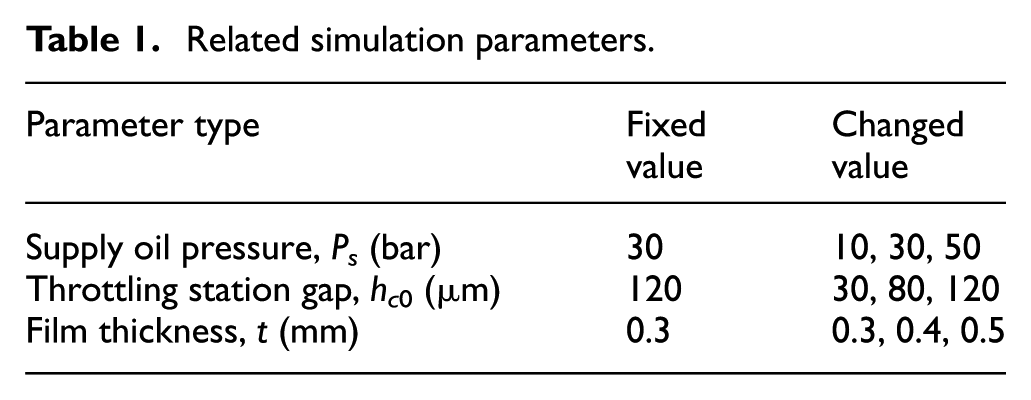
In the design of the film restrictor hydrostatic bearing, the pressure ratio is closely related to the bearing capacity, the oil film stiffness, the bearing flow, and so on. It is an important basis for the design of hydrostatic bearings. When moving parts are subjected to the rated load, in order to reach the optimum stiffness value, stiffness is achieved theoretically to be “infinite.” Requirement increases throughout the range of the bearing load, stiffness is always positive, the use of small enough requirements of moving part displacement is ensured, and the bearing feedback restrictor system has good stability and possibilities at the same time. Therefore, this simulation analysis will investigate when the film restrictor will vary under different pressure ratios and the relationship between restrictor diaphragm and feedback performances. The parameters of the film restrictor are shown in Table 1.
Related simulation parameters.
Analysis of the impact of oil pressure
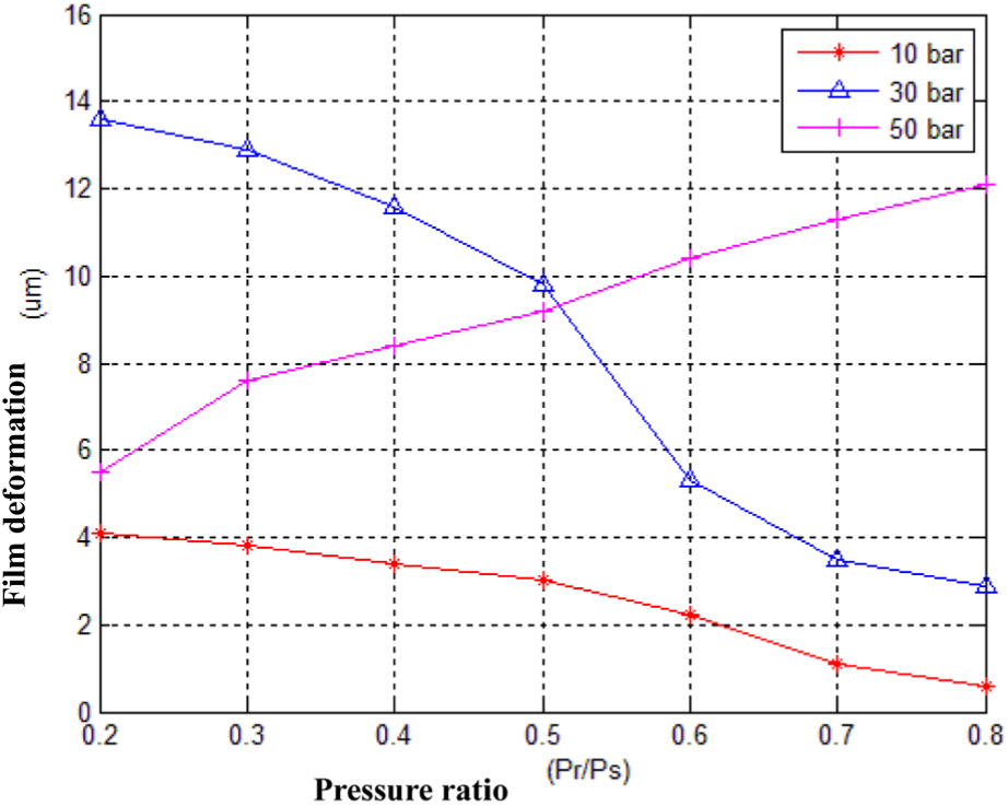
The impact of changes in oil pressure is shown in Figures 6 and 7. When the oil pressure is at 10 and 30 bar, both the pressure ratio (when there is load bearing) and the hydraulic resistance of the restrictor increase; in contrast, when the oil pressure is at 50 bar, the pressure ratio increases and the hydraulic resistance of the restrictor decreases. It can be seen that when the bearing load increases, the film restrictor will supplement the required flow at a time; that time when the oil pressure is at 50 bar, the oil chamber pressure increases, which results in the deformation of the film and then feedback flow upward deformation. This means that the film restrictor pressure had been through feedback mechanism to produce effects. And the magnitude of the feedback pressure will vary with the load pressure.

Relationship between film deformation and pressure ratio under different supply oil pressure.

Relationship between throttling station hydraulic resistance and pressure ratio under different supply oil pressure.
Analysis of the impact of the restrictor gap
The impact of changes in the restrictor table gap is shown in Figures 8 and 9. When the restrictor table is at 30-µm gap, both the pressure ratio and the film deformation increase, but the hydraulic resistance of the restrictor decreases. When the bearing has load, the film restrictor will have the effect of pressure feedback. In contrast, the restrictor gap, 80 and 120 µm, occurs when the bearings are loaded and there is no feedback mechanism. When the film restrictor has feedback, the deformation of the diaphragm is more obvious than that without feedback.
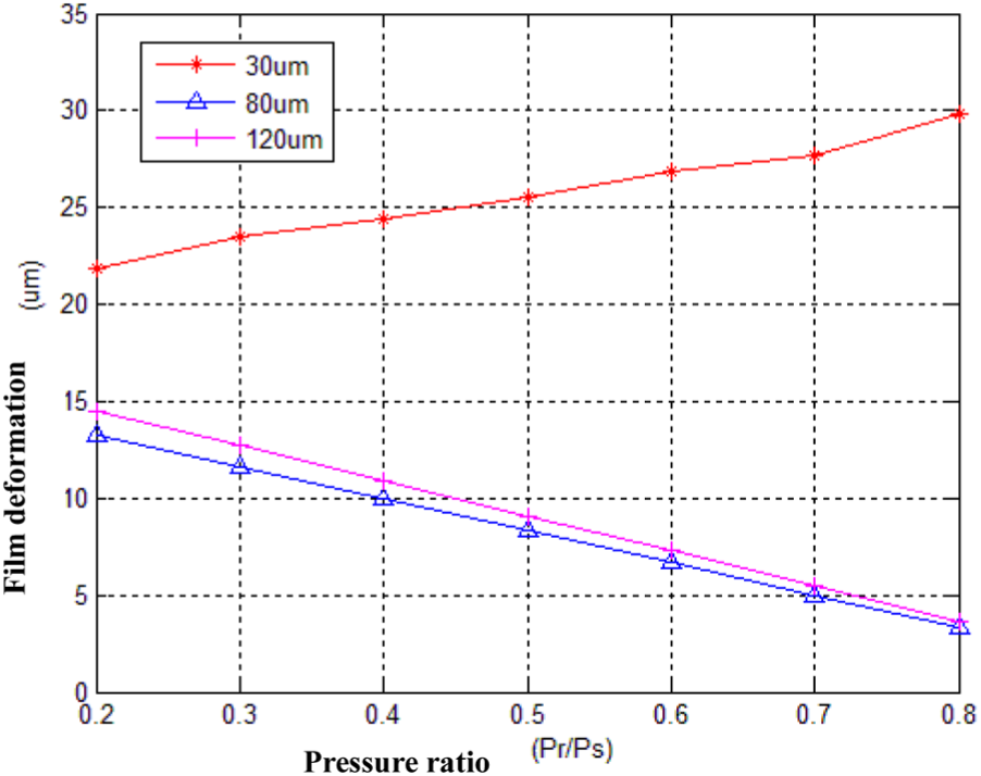
Relationship between film deformation and pressure ratio under different restrictor table gap.
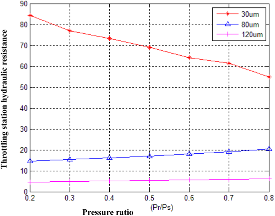
Relationship between restrictor station hydraulic resistance and pressure ratio under different restrictor table gap.
Analysis of the impact of diaphragm thickness
Changes affect the thickness of the diaphragm, as shown in Figures 10 and 11, which show the deformation of the film and the liquid resistance. Due to changes in preload, thin film (30 μm) is used to make dramatic film; with thinner film (30 μm), the film changes dramatically due to preload and the movement is less obvious with a thicker film. Therefore, the overall performance of the film will be better in the thinner film. The simulation results also confirmed the design of the film restrictor from the manual, which generally used two kinds of diaphragm thicknesses: 30 and 40 μm, and the diaphragm should not be too thin, for processing. Its non-parallelism should be less than 20 μm. In the figures, red line represents 30 μm, blue line represents 40 μm, and pink line represents 50 μm.
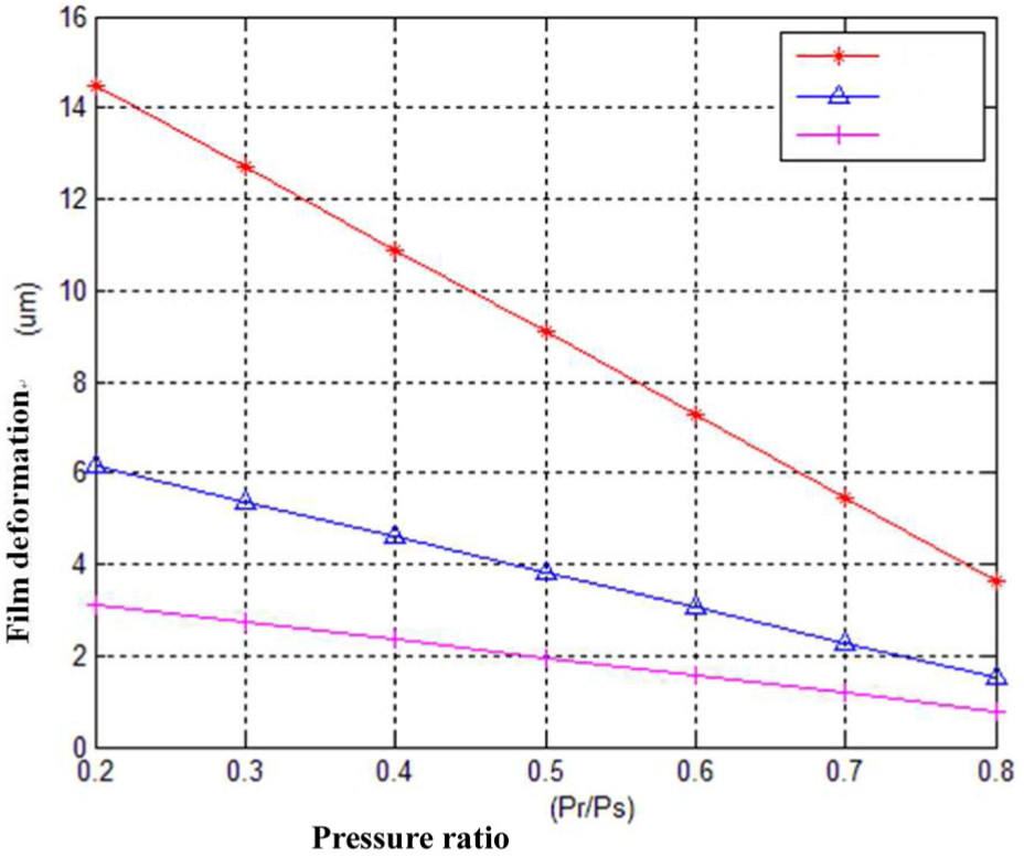
Relationship between film deformation and pressure ratio under different diaphragm thicknesses (red line represents 30 μm, blue line represents 40 μm, and pink line represents 50 μm).

Relationship between throttling station hydraulic resistance and pressure ratio under different diaphragm thicknesses (red line represents 30 μm, blue line represents 40 μm, and pink line represents 50 μm).
Experimental results
Three kinds of oil supply pressure Ps , 10, 30, and 50 bar, were used in this study. Figures 12 and 13 indicate the generation of oil pressure along with different load pressures.
Experiment diagram of film deformation and pressure ratio.

Experiment diagram of throttling station hydraulic resistance and pressure ratio.
The experimental results show that there is a downward trend in the film deformation when the load pressure is adjusted to supply pressure of 10 and 30 bar, and then it is enhanced to a supply pressure of 50 bars. In the meanwhile, film deformation of the film restrictor increased as the load increased, but the fluid resistance of the restrictor decreased. However, pressured feedback effect is also found as the supply pressure at 50 bar. When the oil pressure is at 10 and 30 bar, there is no feedback of the phenomenon, the supply pressure increases, and the film changes more dramatically.
Figure 14 shows the experiment diagram of film throttle diaphragm measurement. Figure 15 shows the film restrictor entity diagram. Figures 16 –18 show the comparison chart of simulation analysis and experimental data. It was found from the graph that at low oil pressure (10 bar), the simulation analysis and experimental data have trend slightly; when there is a pressure ratio of 0.5, the experimental results and simulation analysis have intersected phenomenon. When the oil pressure is at 30 bar, the experimental data and simulation analysis have a larger drop and expressed higher oil pressure. The actual diaphragm moves more violently. Unlike the oil pressure of 10 bar, at the oil pressure of 50 bar, the restrictor had pressure feedback effect. Therefore, the diaphragm actuation is not as violent as that of 30 bar. Its simulation analysis and experimental data are not consistent with 10 bar, but with the same trend.

Experiment diagram of film throttle diaphragm measurement.

Film restrictor entity diagram.
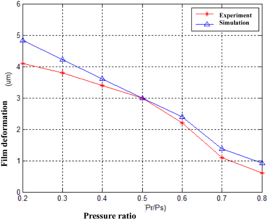
Experimental and simulation data of 10-bar supply oil pressure.

Experimental and simulation data of 30-bar supply oil pressure.

Experimental and simulation data of 50-bar supply oil pressure.
Conclusion
In this article, a characteristic analysis of thin film restrictor for hydrostatic bearing was performed. Based on the above simulation and experimental results, the following conclusions can be drawn:
When the thicker film is chosen, the thickness of the film is more easily deformed at 30 μm, and the overall performance of the film will be better when the thinner film is used. However, the actuating mode of the membrane restrictor must be taken into account in the design, and the diaphragm should not be too thin, for processing.
According to the experimental and simulation results, when the oil supply pressure is at 10 bar, the trend of the film deformation is slightly the same, and there is a big drop in the oil supply pressure at 30 and 50 bar, but with the same trend.
Footnotes
Handling Editor: Bing Xiao
Declaration of conflicting interests
The author(s) declared no potential conflicts of interest with respect to the research, authorship, and/or publication of this article.
Funding
The author(s) received no financial support for the research, authorship, and/or publication of this article.