
Abstract
The collision simulation between a city tram and a car at a level crossing is carried out based on the multi-body dynamics. Compared with the finite element method, this method has an obvious advantage of fast computation speed, so that it is convenient for the study on the dynamic responses and derailment mechanism of railway vehicles during a collision accident. The simulation results show that when a city tram is laterally impacted by a car at a level crossing, the dynamic response and the derailment risk of the collided city tram are greatly influenced by the boundary conditions, such as the mass and speed of the colliding car, the structural arrangement and the loading condition of the city tram. Moreover, in terms of the space limitation of the city tram, two measures are proposed to decrease the lateral impact force during its transition from car body to wheel set. One is to use the secondary damper and the other is to increase the secondary lateral clearance. The simulation results point out that the derailment coefficient of the improved city tram can be reduced by 52%, from 1.63 to 0.79.
Introduction
Tramway is a very important mode of urban passenger transport and it is operated in more than 400 cities all over the world. At present, city trams are operated in 11 cities in China with a total length about 214 km. Besides that, more than 50 city tram lines in China with a total length more than 2000 km are under construction. 1 On the other hand, several collision accidents of city tram happened, resulting in injuries to drivers, passengers and pedestrians, as shown in Figure 1. In these collisions, some collided city trams derailed.

Collision accidents in China.
In the past years, in order to improve the crashworthiness of rail vehicles, various standards and principles were proposed, in which rail vehicles were designed to deform in a controlled step-by-step pattern to minimise the damage resulting from train collisions.2–6 Based on the project SAFETRAM, 7 the European standard EN 15227 8 was published in 2008. Since then, the researches on the crashworthiness of rail vehicles have been mainly concentrated in the front-end collisions (according to the EN 15227).
Actually, in terms of the city tram, the collision with a car at a level crossing is more likely to occur. 9 Compared with the front-end collision, when a city tram is impacted laterally by a car at a level crossing, the collided city tram has a higher risk to derail. Under this background, in order to prevent the collided city tram from derailment, the derailment mechanism is analysed in this article based on the collision simulation between a city tram and a car at a level crossing. Although the collision simulations are widely carried out according to the finite element method (FEM),10–13 it takes amounts of computation time. Besides that, in these models, only the car body structures are meshed with fine grids; the bogie parts are usually not included or extremely simplified (e.g. the wheel-rail contact is always simplified as the contact between a circle and a flat). Due to these reasons, these FEM models are not suitable to predict the vehicle derailment risk during a collision accident. Unlike FEM, multi-body dynamics have the advantage of predicting the gross motion of railway vehicles, so that it is convenient for the study on the dynamic responses and derailment mechanism of the city tram during a collision accident.14–20 Besides that, in order to define the impact force between the city tram and car, the contact element ‘Force Element 196: Elastic–Plastic Spring’ is proposed.
Modelling
The modelling is undertaken using the software Simpack. This simulation tool enables engineers to generate and solve virtual 3D models. The use of such code allows accurate and meaningful analysis of complex mechanical systems, such as the present city tram.
City tram
The city tram contains five modules, including three modules with bogies and two suspended modules (Figure 2(a)). The adjacent modules are connected by a lower spherical joint located at each end of the car bodies. Figure 2(b) shows a detailed view of the module with bogie. The primary suspension consists of linear springs in three directions. The secondary suspension is built up of vertical dampers, springs and lateral bump stops, which are usually used to constrain the maximal relative lateral movement between car body and bogie. Its characteristic is modelled by a nonlinear spring. The forces between wheel and rail are calculated using the FASTSIM algorithm of Kalker. 21 The dynamic model of the city tram is shown in Figure 2(c) and its basic parameters are listed in Table 1.

Model of the city tram: (a) sketch diagram of the city tram, (b) sketch diagram of the module with bogie and (c) dynamic model of the city tram in Simpack.
Basic parameters of the city tram. 16

Car
Since the objective of this research is the dynamic responses of the collided city tram, the car model is simplified as a rigid body (lumped mass) impacting the city tram laterally (Figure 2(c)). During the collision, the frontal structure of the car impacts with the under frame of the city tram. Therefore, the impact position is assumed to be in the middle of the car bumper and at the under frame of the city tram, respectively. As the under frame of the city tram is usually much stiffer than the frontal structure of the car, the colliding car deforms seriously and absorbs most of the collision energy. Due to this reason, the impact force between city tram and car is defined as a function of the car frontal stiffness and modelled by the contact element ‘Force Element 196: Elastic–Plastic Spring’. Several force–displacement curves of the car frontal structures are shown in Figure 3, which are obtained from the car collision experiments in reference. 22 These curves consist of three steps, corresponding to the following phases: 19
Bumper deformation (Phase 1): Bumper is the first contact device when the car impacts the city tram.
Front structure deformation (Phase 2): When the impact speed is larger, not only the bumper but also the front structures commence plastic deformation.
Cabin deformation (Phase 3): As the front structures fail, cab structures impact the city tram and commence plastic deformation. Therefore, a significantly increased impact force is induced at the collision interface.

Force–displacement curves of frontal structures of different cars. 19
The friction force between the car and the city tram during the collision is also taken into consideration. Therefore, the impact force vector Fc = [Fcx, F cy , Fcz, Mcx, Mcy, Mcz] acting on the city tram (Figure 4) is expressed as


where Fcy is the normal impact force;

Impact forces on city tram.
Collision between a city tram and a car at a level crossing
As shown in Figure 2(c), the collision between a city tram and a car at a level crossing is simulated. The city tram runs in the x direction with a speed of 20 km/h, while the car (Audi A4) with a mass of 1.6t runs in the y direction with a speed of 20 km/h. The initial distance (in y direction) between the city tram and car is 1 m so that the car impacts the first module of the city tram at t = 0.18 s.
The lateral velocities (in y direction) of the city tram and car are shown in Figure 5(a). During the collision, most collision energy is absorbed by the car frontal structure by means of plastic deformation, so that the car velocity decreases dramatically, from the initial speed 20 km/h to 0. Meanwhile, the collided city tram rocks very slightly. Since the mass of the city tram is much larger than that of the car, as shown in Figure 5(b), the maximum lateral acceleration of the city tram is only 13 m/s2 and much lower than the threshold (7.5 g) defined in EN 15227. In contrast, the maximum lateral acceleration of the car is up to 161 m/s2, which means the occupants in the car suffer a severe secondary impact. Figure 5(c) shows the impact force at the collision interface. It can be seen that the maximum impact force and plastic deformation are 259 kN and 0.166 m, respectively. Compared with Figure 3, it can be found since the impact speed is relative small (20 km/h), only the bumper and parts of the frontal structure are collapsed. The cabin of the car keeps well and without plastic deformation.
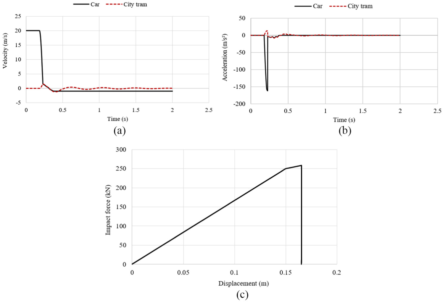
Dynamic responses of the city tram and car: (a) velocity, (b) acceleration and (c) impact force.
Figure 6 shows the dynamic responses of the collided city tram. During the collision, the car body, bogie frame and wheel set move leftwards under the large impact force and the flange of the left wheel comes into contact with the rail at the time of 0.288 s (Figure 6(a)). As a result, the wheel–rail contact force of the left wheel increases largely and tends to prevent the wheel set from moving leftwards. The derailment coefficient Y/Q (ratio of lateral to vertical wheel-rail force) of the left wheel also increases dramatically (Figure 6(b)) and reaches the peak value about 1.63, exceeding the limit (1.2) defined in EN 14363. 23 That means the collided city tram is likely to derail. The maximal lateral displacement and velocity of the car body are 0.028 m and 0.41 m/s, respectively. Compared with the roll motion (Figure 6(d)), it can be found that when the city tram is collided by a car at a level crossing, the lateral motion is in priority and the roll motion is so slight that it can be neglected.

Dynamic responses of the city tram: (a) lateral displacement and roll angle, (b) derailment coefficient, (c) lateral velocity and (d) roll angular velocity.
The computation time of this simulation is only several minutes. Compared with the FEM simulation, it has an obvious advantage of fast computation speed. Due to this reason, the methodology carried out in this simulation is very convenient for the study on the dynamic responses of the collided railway vehicles, especially by different complicated collision boundary conditions.
Contributory factors to the derailment of collided city tram
In reality, the collision accidents of city tram are normally unexpected and the collision boundary conditions are also unpredictable. On the other hand, the dynamic responses and the derailment risk of a collided city tram are seriously affected by many factors, such as the impact speed and impact position. Due to this reason, several contributory factors to the derailment of the collided city tram are analysed in this section.
Car speed
Several collision scenarios are simulated to analyse the effect of the car impact speed on the derailment risk of the city tram. Since the kinetic energy of the car is proportional to the square of its speed, when the car speed increases from 10 to 40 km/h, the maximal impact force and plastic deformation increase from 137 to 378 kN and from 0.082 to 0.381 m, respectively (Figure 7(a)). Meanwhile, the maximal lateral velocity and derailment coefficient of the collided city tram increase from 0.22 to 0.8 m/s and from 0.53 to 4.08, respectively (Figure 7(b) and (c)). Compared with Figure 3, it can be pointed out that when the impact speed is more than 20 km/h, not only the bumper but also parts of the frontal structure are collapsed. As a result, the derailment coefficient exceeds the limit (1.2) and the collided city tram has a high risk to derail. Due to this reason, the car speed at a level crossing is proposed to be under 20 km/h.

Effect of the car impact speed: (a) impact force, (b) lateral velocity and (c) derailment coefficient.
Car mass
Since the kinetic energy of the car is proportional to its mass, when the car mass increases from 1.2t to 2t, the maximal impact force increases from 240 to 270 kN (Figure 8(a)). Meanwhile, the maximal lateral velocity and derailment coefficient of the collided city tram increase from 0.34 to 0.52 m/s and 1.08 to 2.13, respectively (Figure 8(b) and (c)). From the simulation results, it can be indicated that the collided city tram is more likely to derail, when it is laterally impacted by a heavy bus or truck rather than a light car.
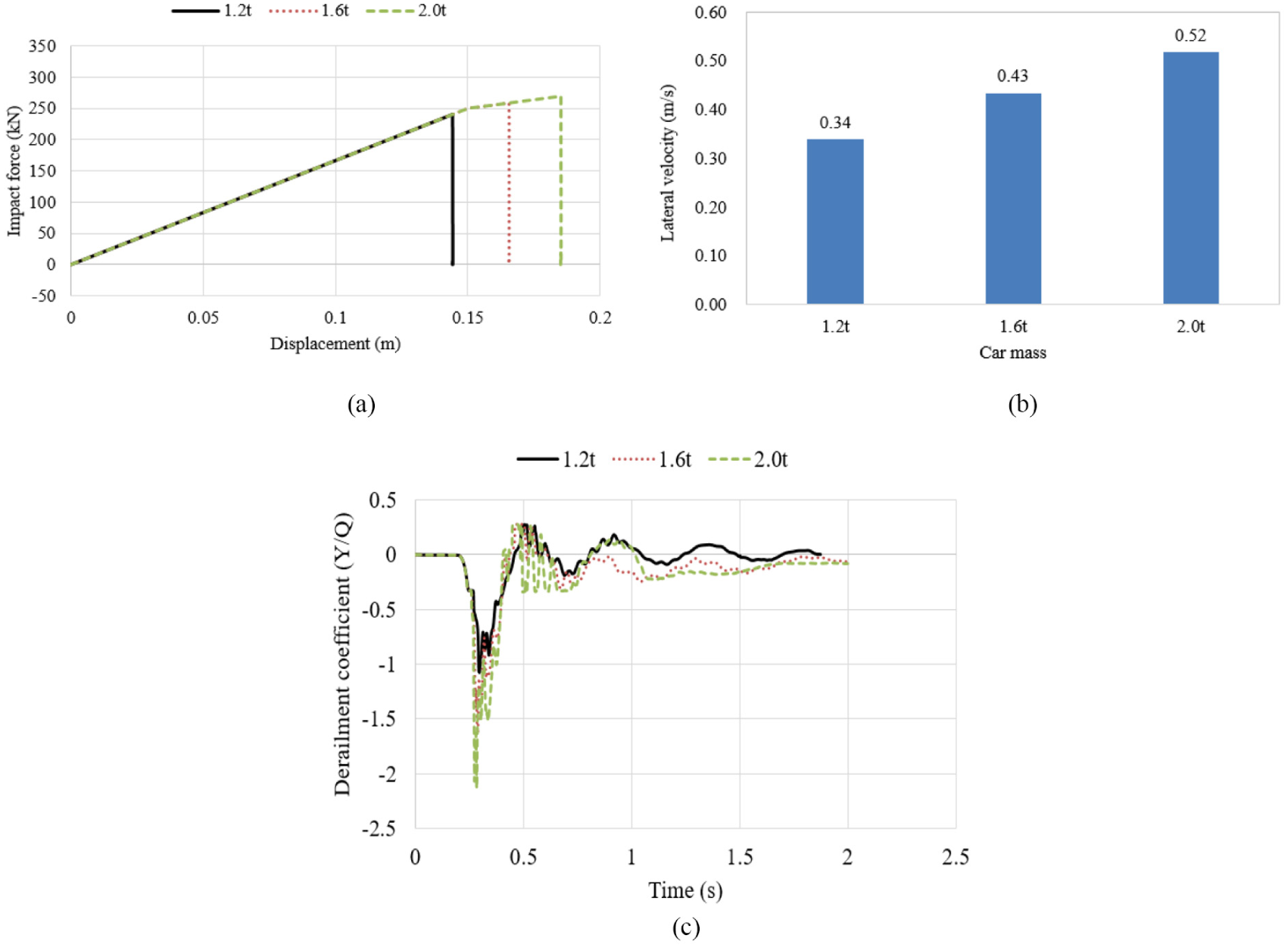
Effect of the car mass: (a) impact force, (b) lateral velocity and (c) derailment coefficient.
Impact angle
In reality, car drivers usually try to turn the steering wheel to avoid collision accident. As a result, when a car impacts a city tram at a level crossing, the city tram is not always impacted laterally (90°), but with an oblique angle. As shown in Figure 4, when the city tram is impacted obliquely, the normal impact force at the impact interface has a component in the longitudinal direction (x direction), so that the lateral impact force (y direction) decreases according to the impact angle. As shown in Figure 9, when the impact angle decreases from 90° to 45°, the maximum lateral impact force decreases from 259 to 195 kN, and the derailment coefficient decreases from 1.63 to 0.94. That means the city tram has a low risk to derail when it is collided by a car obliquely. However, it should be indicated that when a car impacts a city tram obliquely, the force–displacement curve of the car frontal structure varies a lot according to the oblique angle. This effect is not taken into account in this article.

Effect of the car impact angle: (a) lateral impact force and (b) derailment coefficient.
Stiffness of the car frontal structure
There are numerous brands and types of cars running all over the world. Different cars have different frontal stiffness. In this section, three types of cars are selected, whose frontal stiffness is shown in Figure 3. It can be seen that the Volvo XC90 has the strongest frontal stiffness and the Ford Focus has the weakest. The simulation results in Figure 10 point out when a city tram is impacted laterally by a car at a level crossing, the stiffness of the car frontal structure has little effect on the dynamic responses of the collided city tram. On the other hand, with the increased frontal stiffness, the colliding car suffers a higher deceleration but a lower plastic deformation.

Effect of the car frontal stiffness: (a) lateral velocity of the city tram, (b) derailment coefficient of the city tram, (c) impact force and (d) car acceleration.
Loading mass of the city tram
As the collision energy depends mainly on the kinetic energy of the colliding car, it is reasonable to assume that the collision energy is almost the same whether the city tram is heavy loaded or empty. Therefore, by the same lateral impact force, the derailment coefficient is smaller when the axle loads are heavier. As illustrated in Figure 11, the lateral velocity of the collided city tram decreases about 19%, when the loading mass of the city tram increases from the AW0 (empty condition) to the AW3 (over loading condition). Meanwhile, the derailment coefficient also decreases significantly from 3.05 to 1.4, about 54%.
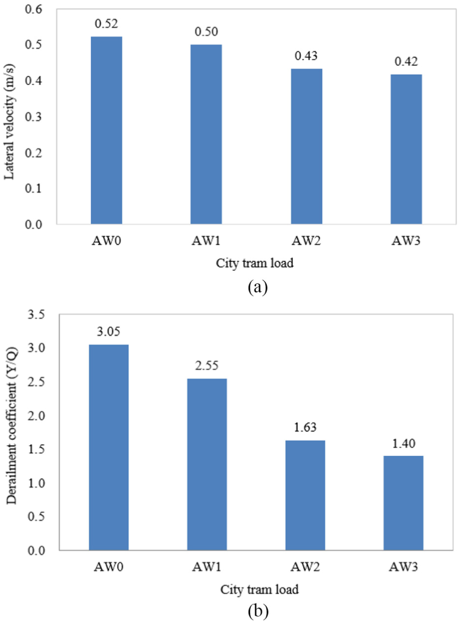
Effect of the loading mass of the city tram: (a) lateral velocity and (b) derailment coefficient.
Friction coefficient between wheel and rail
As we all know, the friction coefficient between wheel and rail is an important factor to determine the wheel–rail contact force. When a city tram is impacted by a car at a level crossing, the car body of the collided city tram moves leftwards (Figure 6(a)). As a result, the flange of the left wheel comes into contact with the rail. At this time, the wheel–rail friction force tends to prevent the left wheel from climbing up the rail. When the friction coefficient decreases due to bad weather (such as rain or snow), the friction force decreases. By the same impact force, the wheel set has a larger lateral displacement. As shown in Figure 12(a), when the friction coefficient decreases from 0.4 to 0.1, the lateral displacement of wheel set increases from 7.83 to 8.16 mm. As a result, the contact point of the left wheel moves along the wheel profile further downwards. It is more likely to cause the left wheel to climb up the rail. As shown in Figure 12(b), the derailment coefficient of the left wheel increases to 2.33, when the friction coefficient decreases to 0.1. That means the collided city tram is derailed. Moreover, when the friction coefficient decreases, the required brake distance increases. The collision accidents are more likely to occur.
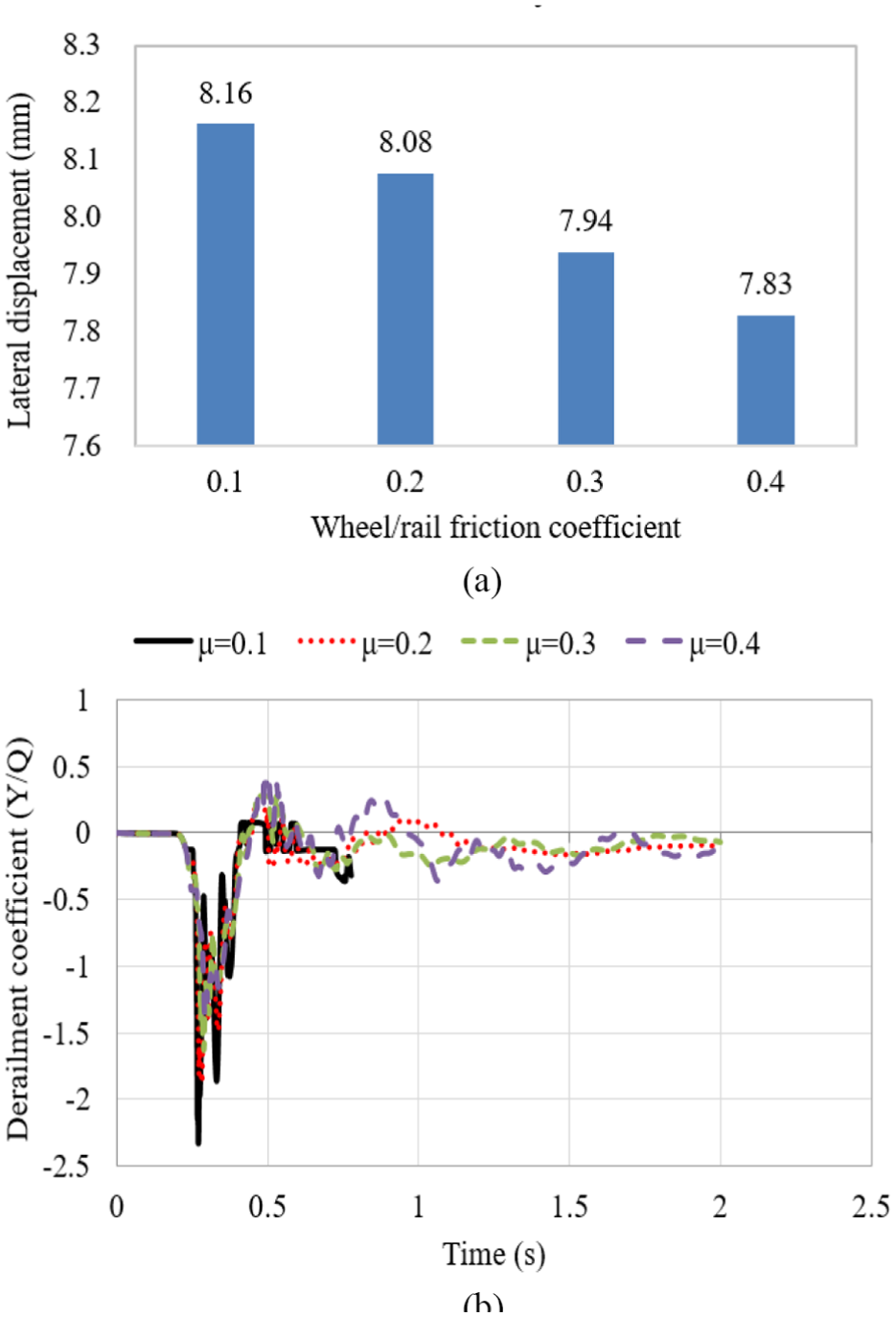
Effect of the friction coefficient between wheel and rail: (a) lateral displacement and (b) derailment coefficient.
Impact point position
Figure 13 shows the effect of the impact point position on the dynamic response of the collided city tram. When the impact point is not located at the mass centre of the car body (module 1) but with a longitudinal distance (in x direction as shown in Figure 2(c)), a yaw moment is generated. As shown in Figure 13(a), with the increased longitudinal distance between the impact point position and the mass centre of the car body, the yaw acceleration of the car body increases obviously. As a result, the derailment coefficient of the collided city tram increases to 2.17 (Figure 13(b)). Besides that, in terms of the common five-module city tram, the dynamic responses of the city tram are different, when different modules are impacted by a car at a level crossing. As shown in Figure 2(a), when the front or the end module (module M1 or M2) is impacted by the car, the lateral impact force is transmitted unidirectionally to the adjacent module by the inter-vehicle joint. On the other hand, when the middle module (module C1, NP or C2) is impacted, the lateral impact force can be transmitted bidirectionally. As a result, this impact force is endured by more modules. As shown in Figure 13(c), when the front or the end module is impacted by the car, the derailment coefficient of the collided city tram is larger and exceeds the limit (1.2) defined in EN 14363.
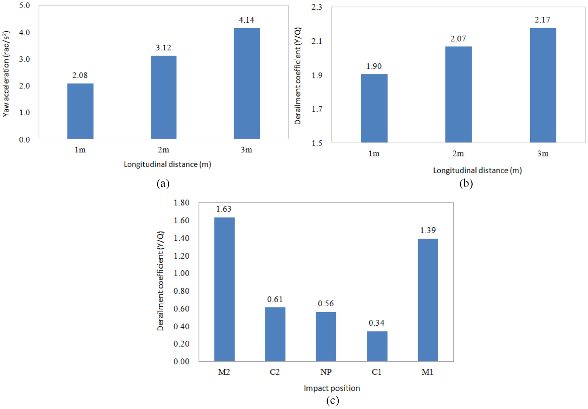
Effect of the impact point position: (a) yaw acceleration of the car body, (b) derailment coefficients by different longitudinal distances and (c) derailment coefficients by different modules.
Measures against derailment during collision
Due to the space limitation, it is difficult to consider structures to absorb the collision energy, when the city tram is laterally impacted by a car at a level crossing. By the large impact force, the collided city tram moves laterally and this impact force is then transmitted from car body to bogie and wheel set. When the impact force acting on the wheel set is so large that the lateral movement of the wheel set is hardly constrained by the rail, the derailment phenomenon is likely to occur. Due to this reason, in order to decrease the derailment risk of the collided city tram, it is reasonable to adopt some measures to decrease the impact force during its transmission from car body to wheel set. Two measures are proposed: one is to use the secondary lateral dampers to absorb the collision energy. The other is to increase the secondary lateral clearance to store more collision energy in springs.
Nowadays, the secondary lateral damper is not equipped for some city trams. However, if this damper is adopted, it can absorb some collision energy and decrease the impact force transmitted to wheel set. Therefore, the safety against derailment can be improved. As shown in Figure 14(a), the derailment coefficient of the collided city tram decreases from 1.63 to 1.13, when the lateral damper increases from 0 to 60,000 N s/m.

Derailment coefficients: (a) effects of the secondary lateral damper, (b) effects of the secondary lateral clearance and (c) differences between the original and improved city tram.
During the collision, the maximum elastic potential energy stored in a spring can be expressed as

where y is the lateral displacement between car body and bogie, whose maximal value is half of the lateral clearance. When the lateral clearance increases, more collision energy is stored in the secondary suspension. Therefore, there is less impact force transmitted to the wheel set and the safety against derailment can be improved. As shown in Figure 14(b), the maximal derailment coefficient decreases from 1.63 to 1.26, when the lateral clearance increases from 8 to 16 mm.
Figure 14(c) compares the derailment coefficients between the original and improved city tram. Since the secondary lateral damper is adopted (60,000 N s/m) and the lateral clearance is also increased to 16 mm, the derailment coefficient of the improved city tram decreases obviously from 1.63 to 0.79, under the limit (1.2) defined in EN 14363.
Conclusion
The collision simulation between a city tram and a car at a level crossing is carried out based on the multi-body dynamics. Compared with the FEM, this method has an obvious advantage of fast computation speed, so that it is convenient for the study on the dynamic responses and derailment mechanism of railway vehicles during a collision accident.
The simulation results show that when a city tram is laterally impacted by a car at a level crossing, the dynamic response and derailment risk of the collided city tram are greatly influenced by the boundary conditions, such as the impact speed and position, masses of the car and city tram, car frontal structure stiffness. With the increased impact mass and speed of the colliding car, the impact force is obviously increased. As a result, the derailment coefficient of the collided city tram is also gradually increased. On the other hand, when the loading mass of the city tram is increased from the AW0 (empty condition) to AW3 (over loading condition), the derailment coefficient is decreased about 54%. When the first or the last module of the city tram is collided by the car, the lateral impact force can be transmitted to the adjacent module unidirectionally, which results in a high derailment coefficient. Besides that, by the bad weather condition, with the reduced friction coefficient, the wheel–rail constraint forces against the lateral motion of wheel sets decrease. As a result, the collided city tram is more likely to derail.
Moreover, in terms of the space limitation of the city tram, two measures are proposed to decrease the lateral impact force during its transition from car body to wheel set. One is to use the secondary damper and the other is to increase the secondary lateral clearance. The simulation results point out that the derailment coefficient of the improved city tram can be reduced by 52%, from 1.63 to 0.79.
Footnotes
Appendix 1
Handling Editor: Davood Younesian
Declaration of conflicting interests
The author(s) declared no potential conflicts of interest with respect to the research, authorship and/or publication of this article.
Funding
The author(s) disclosed receipt of the following financial support for the research, authorship and/or publication of this article: This work was supported by the National Key R&D Program of China (no. 2018YFB1201603-08), the Fundamental Research Funds for the Central Universities (no. kx0286020172695) and the Shanghai Pujiang Programme (no. 16PJ1409500).