
Abstract
When the load acting on a mechanical structure is greater than the yield strength of the material, the contact surface will undergo plastic deformation. Cumulative plastic deformation has an important influence on the lifespan of mechanical parts. This article presents a three-dimensional semi-analytical model based on the conjugate gradient method and fast Fourier transform algorithm, with the aim of studying the characteristic parameters of the contact region between a rigid ellipsoid and elasto-plastic half-space. Moreover, normal forces and tangential traction were considered, as well as the contact pressure resulting from various sliding speeds and friction coefficients. The contact pressure, effective plastic strain, von Mises stress, and residual stress were measured and shown to increase with increasing sliding velocity. Finally, when the friction coefficient, contact pressure, and effective plastic strain are increased, the von Mises stress is also shown to increase, whereas the residual stress decreases.
Introduction
A machine tool is not a continuous entity but can be considered an integrated collection of components with individual movements and functionalities. The mutual surface connecting two or more components is referred to as a junction and understanding the sliding characteristics at the junction between two components is crucial to understanding certain friction phenomena, including abrasion, contact fatigue, and sealing. At the microscopic level, the actual contact at the junction surface occurs between a series of asperities as a result of the roughness of the contact surfaces. Furthermore, non-uniform roughness of the contact surfaces can lead to high stresses at each point of contact resulting in plastic deformation. Cumulative plastic deformation is an important factor affecting the lifespan of mechanical components. Therefore, studies on the contact characteristics of engineered contact surfaces at the micro-level are of both theoretical and practical importance.
The finite element (FE) method has been widely used to solve elasto-plastic contact problems. Kogut and Etsion 1 developed an elasto-plastic FE model describing frictionless contact between a deformable sphere and a rigid flat surface and provided dimensionless expressions for the contact load, contact area, and mean contact pressure. Moreover, accurate FE solutions of elasto-plastic contact problems were obtained using appropriate constitutive laws, depending on the mode of deformation, that is, elastic or plastic. The FE method was also used to model the elasto-plastic deformation between a sphere and a rigid flat surface exposed to tangential loading. 2 Then, using the model, analytical expressions representing changes in the friction coefficient during elasto-plastic contact were developed by considering the physical properties of each material.
One advantage of the FE method is that the behavior of complex materials can be simulated; however, previous studies mainly focused on two-dimensional (2D) elasto-plastic contact problems since three-dimensional (3D) simulations are time-consuming and convergence is more difficult to achieve. As such, other types of numerical method are typically used to simulate 3D contact problems of real machining surfaces and are more efficient since, unlike FE models, only the contact region needs to be meshed and simulated. A 3D semi-analytical elasto-plastic contact model and reciprocal theorem were proposed by Jacq et al., 3 in which the contact surface geometry was considered as a function of contact pressure and plastic strain. Moreover, the irreversible plastic deformation case was modeled and led to the development of an incremental formula for the elasto-plastic contact problem and the corresponding solution algorithm. The main advantage of the model is reduced calculation times, thereby making the transient analysis of 3D contact problems more feasible. An integration-based multilevel contact model was introduced by Wang et al. 4 to study elasto-plastic contact between a smooth sphere and the half-space of a machined surface. In the model, deformation of each asperity was taken into account, and the total surface deformation was shown to be composed of both the bulk material deformation and cumulative deformation of the asperities. Furthermore, the model was shown to be capable of accurately and rapidly predicting the contact area and contact pressure under a given load using a relatively coarse grid system. Furthermore, Li et al. 5 established a numerical model for studying a spinning rigid sphere against an elasto-plastic half-space under combined normal and torsional loading. The von Mises stress and equivalent plastic strain during contact were calculated and an empirical formula was proposed to predict the contact area. In addition, the plastic region within the half-space was estimated. Similarly, Chen et al. 6 established a 3D elasto-plastic point contact numerical model to simulate repetitive rolling and sliding contact between a rigid sphere and elasto-plastic half-space, and the model was then used to calculate the stress, strain, residual displacement, and plastic strain volume integral of the half-space. When the total load exceeded a certain theoretical shakedown limit, the rolling contact characteristics were determined based on four different hardening laws; moreover, the influence of the friction coefficient on contact performance under repetitive sliding contact was investigated using the model.
The FE method has been used to model the contact region between an ellipsoid and a flat rigid smooth surface. 7 The contact pressure and von Mises stress at the contact area were calculated and analyzed; in addition, the contact pressure, actual contact area, and contact load under different ellipsoid ratios were calculated. Similarly, Chung 8 presented an FE method to investigate the contact between an ellipsoid and a flat rigid surface. In the Chung model, the equivalent von Mises stress and contact displacement under different ellipsoid ratios were calculated and analyzed, and the plastic zone was identified. Yuan et al. 9 established a numerical model of the contact region between a rigid ellipsoid and an elastic substrate and used the model to investigate the micro-level and nano-level contact characteristics, while taking into account surface tension. Furthermore, the contact pressure distribution and actual contact area were calculated. A closed method was developed by Mansoor-Baghaei and Sadegh 10 based on the Hertz theory, Newton method, and linearization scheme to study the contact characteristics of an elastic ellipsoid sheet and elastic half-space. From the model, the maximum total deformation, maximum transmitted force, and the time duration of contact were determined. Variations in the total deflection and transmitted force during contact were also determined for different shell thicknesses and geometries. A semi-analytical model developed by Koumi et al. 11 was used to investigate contact conditions considering the anisotropic elastic inhomogeneities of an ellipsoidal shape. The contact pressure and stress field were also calculated and analyzed.
The FE method and other numerical methods have frequently been used to investigate 2D and 3D elasto-plastic contact, whereas few studies have considered the contact characteristics between a rigid ellipsoid and elasto-plastic half-space. Moreover, there have been very few investigations on the characteristics of junctions between a rigid ellipsoid and elasto-plastic half-spaces using semi-analytical methods and only the contact pressure distribution and von Mises stress were calculated in most cases. Laws governing the variation of important parameters such as contact pressure, equivalent plastic strain, von Mises stress, and residual stress at the junction surface under the different contact conditions, such as different friction coefficients, have not been thoroughly investigated.
In this study, a 3D semi-analytical model was used to study the elasto-plastic contact region between an ellipsoid and half-space under combined normal and tangential loading. Herein, we present a comprehensive analysis of the contact pressure distribution, equivalent plastic strain, von Mises stress, and residual stress of a rigid ellipsoid and elasto-plastic half-space under different friction coefficients. The results presented in this article are significant and will contribute to further understanding the mechanism of sliding actions at the junctions between mechanical components at the micro-level. The semi-analytical model proposed in this article can be used to simulate contact problems and may be useful in a number of applications such as nanoindentation, as previously shown, 9 as well as relays and magnetic recording disks.
Theoretical background
Description of elasto-plastic contact
The dry contact problem can be described using a set of equations that includes two equalities and two inequalities. 12 A solution to the contact problem can thus be obtained by solving a set of simultaneous equations, given as


where W is the total applied load, p(x,y) is the contact pressure at (x,y), Γ c is the surface area across which the contact pressure is not nil, h(x,y) is the total distance between the contact bodies at the point (x,y), hi(x,y) is the initial distance between the contact bodies, u3(B1+B2) is the surface normal displacement of the two bodies B1 and B2, and δ is the rigid body displacement. The displacement relationship between the two bodies in contact is illustrated in Figure 1.

Sliding of the rigid ellipsoid on the surface of the elasto-plastic half-space.
As the mechanical joint surface is loaded, it first experiences elastic deformation until the yield limit is reached, and then plastic deformation occurs. Therefore, the total normal displacement of the joint surface is composed of two parts: normal deformation and plastic deformation.
Calculation of contact displacement
Based on the Boussinesq integral, 13 the elastic surface displacement caused by contact pressure and shear traction can be given as
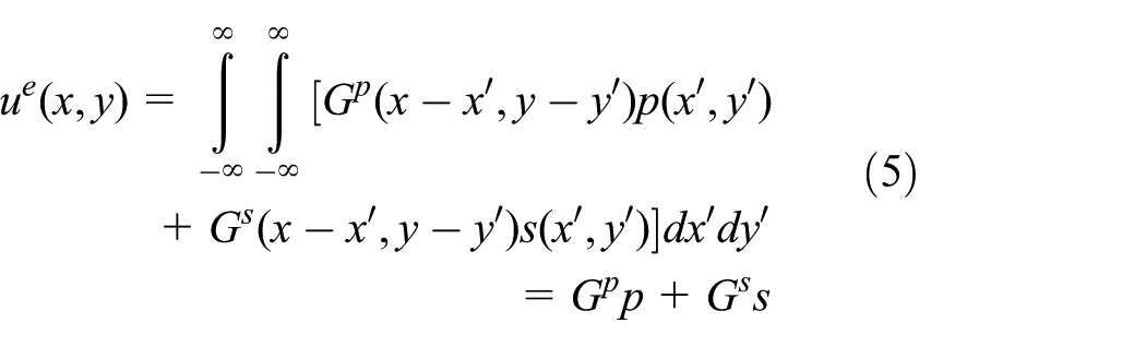
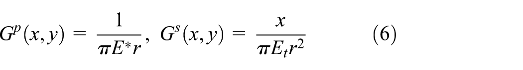
where
where μ is the shear modulus,

To improve computational efficiency, the continuous Green function can be replaced by a discrete influence coefficient. The influence coefficient corresponding to elastic displacement caused by a normal load 6 is given by

where
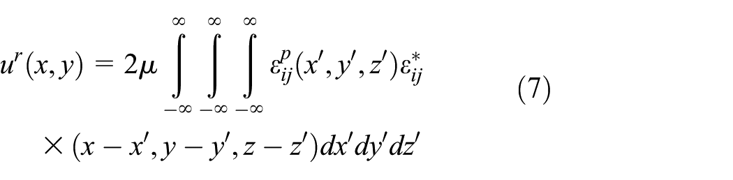
The influence coefficient is related to the displacement caused by the shear and plastic strain, 14 which can be given by
where
Calculation of contact stress
Elastic stress can be expressed in the form of discrete convolution, 6 as shown in Figure 2.

Description of the x–y plane.
Thus, the discrete convolution of elastic strain can be expressed as
where
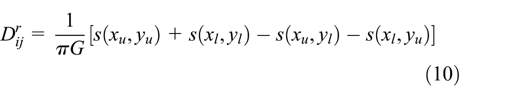
Residual stress at a point M(x1,x2,x3) in the half-space is due to the cuboid of constant plastic strain. Center C has the coordinates (0,0,h) and can be obtained from the following relation

where
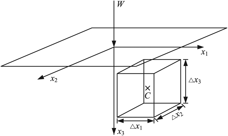
Description of plastic strain.
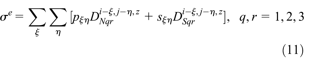
The discrete convolution and fast Fourier transform (DC-FFT) algorithm can be used to solve the linear convolutions presented in equations (11) and (12). The total stress in the contact region between the rigid ellipsoid and elasto-plastic half-space is

Equivalent plastic strain
Plasticity is the irreversible behavior of a material in response to an applied load. The von Mises yield criterion function can be given as

where

where B, C, and n are the work hardening parameters. According to the obtained stress and plastic modulus, the plastic deformation can be obtained using the increment method. At each loading step, the plastic strain changes and can be expressed as a function of stress

A flowchart illustrating the steps of the calculation process is shown in Figure 4.

Flowchart of the algorithm for describing elasto-plastic contact.
Results and discussion
A machined surface is not a smooth surface but consists of numerous heterogeneous asperities. Micrometer measurements of the surface specimens subjected to 40Cr grinding were performed and the surfaces were viewed under a white-light interference confocal microscope (Leica DCM 3D) to observe their roughness. The micromorphology and surface measurement area are shown in Figure 5. Representative images of the 3D topography of a representative surface is shown in Figure 6, illustrating the many convex and concave valleys on the surface as a result of the actual machining process. All the processed surfaces exhibit some degree of roughness and waviness since during the machining process any machined surface, regardless of the processing method, will be subjected to vibrations caused by the machine tool, cutting tool, and workpiece system, as well as plastic deformation due to chip separation, and scratches which form shape errors of various sizes. To simplify the calculations, the non-uniform asperities on the rough surface are assumed to be of an ideal shape. There are many alternative forms of contact models for rough surfaces. The types of asperity include spherical, conical, cylindrical, rod shaped, ellipsoidal, and pyramid shaped. In the calculation and analysis of contact characteristics, the model of the asperities must meet the following criteria: (1) asperities can be described by geometrical shape parameters so that the contact characteristics can be calculated; (2) isotropy and anisotropy of friction must be reflected objectively; (3) elastic, elasto-plastic, and plastic deformation of the contact area can be described. The ellipsoid and cylinder fully meet these conditions.
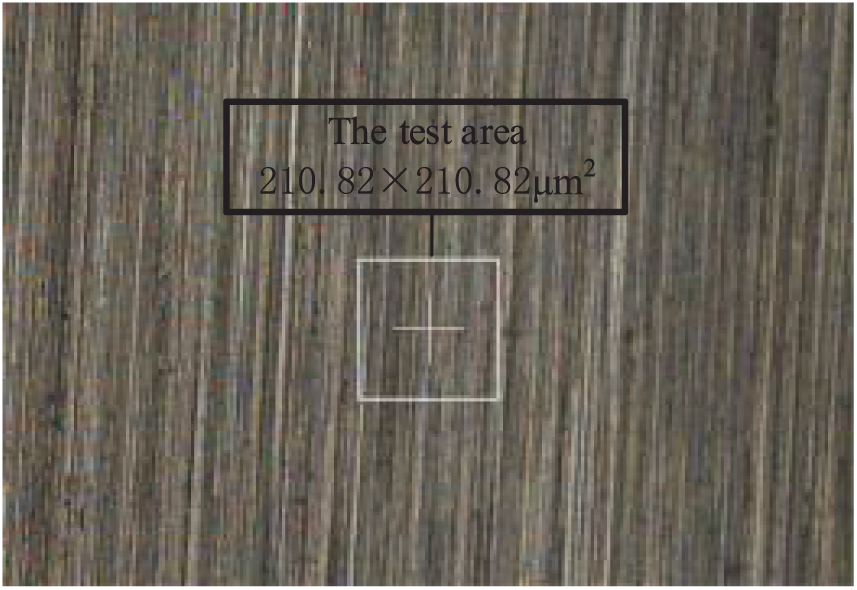
Initial morphology and measurement area of a 40Cr grinding specimen.

Three-dimensional topography of a specimen.
In this article, the microscopic contact area of the mechanical interface is considered to be equivalent to the contact area between a rigid ellipsoid and elasto-plastic half-space (Figure 7). The semi-major and semi-minor axes of the ellipsoid are denoted as a and b, respectively, and the ellipsoid ratio k = b/a 16 and is set at k = 0.5. In order to simplify the numerical simulation, the material of each contact body is assumed to be the same and to have the properties of common steel. First, the rigid ellipsoid is pressed into the half-space along the z-axis under normal loading, and then sliding is introduced by assigning an initial velocity Vs to the rigid ellipsoid such that it slides on the half-space along the positive x direction. Parameters of the simulation and material properties are presented in Table 1. The relationship between the work hardening parameters B, C, and n can be given as


Established model of the contact region between the rigid ellipsoid and elasto-plastic half-space.
Simulation parameters and material properties.
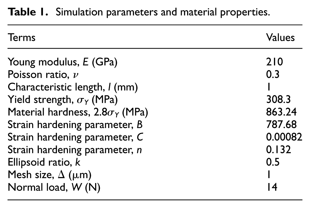
Plasticity is a non-linear property that depends on the loading history of the material. To simulate the actual loading history, the entire loading procedure of a gradually increasing normal load from zero to a maximum value of 14 N can be divided into 14 discrete steps. During each iteration, a small normal load is added to the previous load and additional step loads are added until the final load convergences. When the rigid ellipsoid and elasto-plastic half-space are in contact, the maximum load Wmax is related to the critical load Wc, and the relationship between them is defined as Wmax/Wc = 6. The critical normal load Wc indicates the transition from elastic to elasto-plastic contact. The elasto-plastic transition can be expressed as


where H is the material hardness, E* is the equivalent Young modulus, E1 and E2 are the Young moduli of the half-space and rigid ellipsoid, respectively, and Kh is the hardness coefficient. For the contact region between an ellipsoid and elasto-plastic half-space, Wmax and Wc have a similar relationship, 17 expressed as


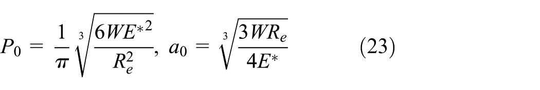
In the above equation, Re is the equivalent contact radius 9 and a and b are the semi-major and semi-minor axes of the ellipsoid, set at a = 10 mm and b = 5 mm, respectively. Using the above formula, Wmax can be calculated and its value is 14 N. To compare the proposed theoretical model with classical Hertz contact theory, the calculated contact pressure and stress were normalized by the Hertz contact pressure, P0 = 897.3 MPa, and yield strength, σY = 308.3 MPa. The spatial variable can then be obtained using the Hertz contact radius a0 = 0.086 mm, and the plastic strain can be given in percentage form. 18 Thus, P0 and a0 can be solved according to 19
The influences of sliding and tangential traction on the spherical contact properties were investigated. Figures 9–14 show the trends in contact pressure, equivalent plastic strain, von Mises stress, and residual stress for the same sliding speed (Vs = 50 m/s) and different friction coefficients (μf = 0.1, 0.15, 0.2, and 0.25). To visually compare these trends, contour maps of each contact parameter based on the variation of the friction coefficient are shown in Figure 8. Then, the graphs presented in Figures 9–14 were obtained at cross-sectional positions shown as black lines in Figure 8.

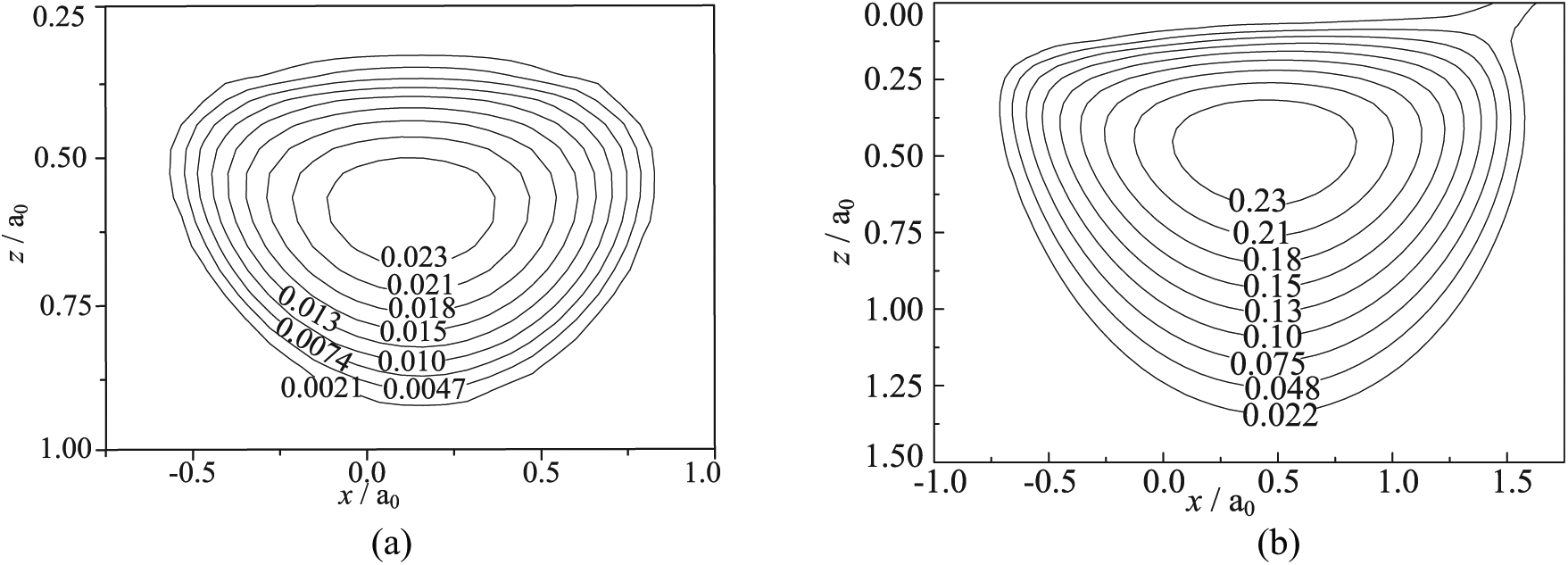
Contour maps of each contact parameter (black line represents the position at which additional contours were plotted along the depth): (a) contact pressure, (b) von Mises stress, (c) effective plastic strain, and (d) residual stress.
Contact pressure profiles along the x-axis for each friction coefficient are compared as shown in Figure 9. The maximum contact pressure increases as the friction coefficient is increased and the contact pressure is shown to be approximately symmetrical about x = 0 when the interfacial friction coefficient is low (uf = 0.1). Figures 10 and 11 show the contours of the subsurface von Mises stress and effective plastic strain, respectively, on the surface of the half-space. The von Mises stress was normalized by σY; therefore, the effective plastic strain is given in percentage form. The von Mises stress field and effective plastic strain field are approximately symmetrical under the lowest friction coefficient, but as the friction coefficient increases, the location of the maximum von Mises stress and maximum effective plastic strain shifts closer to the surface; moreover, the maximum von Mises stress and equivalent plastic strain increase. Changes in the equivalent plastic strain along the depth are shown in Figure 12. It can be seen that by increasing the friction coefficient the equivalent plastic strain increases and the maximum equivalent plastic strain gradually moves closer to the surface. However, no effect on the depth of the plastic zone is observed. Variation in the von Mises stress along the depth direction is shown in Figure 13. As the friction coefficient increases, the von Mises stress also increases near the surface and within the plastic zone, whereas below the plastic zone the von Mises stress does not change. Variation in residual stress along the depth is shown in Figure 14. It can be observed that as the friction coefficient is increased, residual stress within the plastic zone decreases.

Contact pressure profiles along the x-axis corresponding to various friction coefficients.

Contours of the dimensionless von Mises stress,
Contours of effective plastic strain,

Effective plastic strain profiles along the depth corresponding to various friction coefficients.
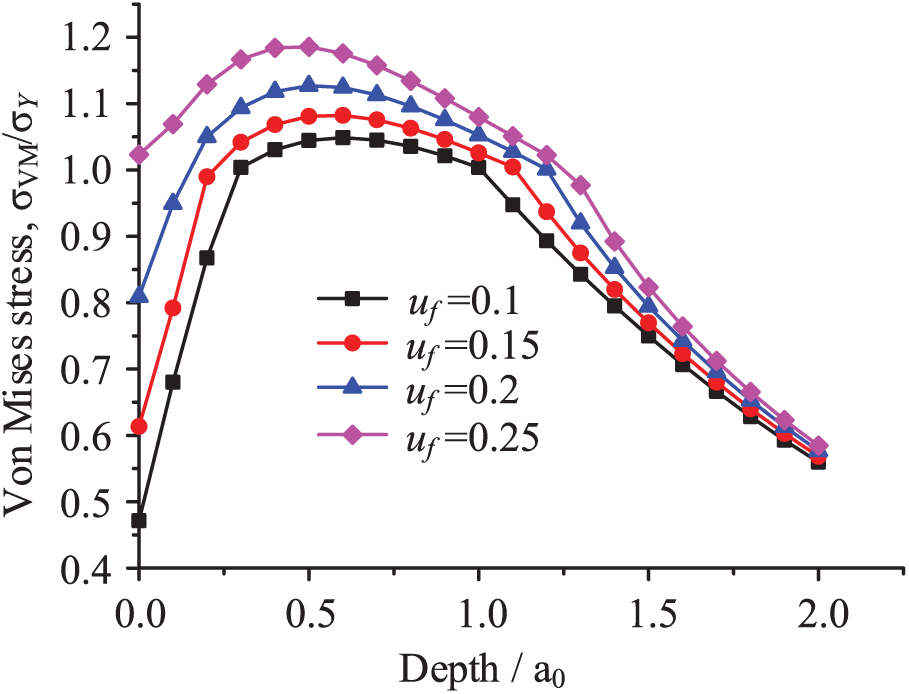
Von Mises stress profiles along the depth corresponding to various friction coefficients.

Residual stress profiles along the depth corresponding to various friction coefficients.
Model verification
To verify the results of the numerical simulation, the FE method was applied to the same contact model. The established FE model is shown in Figure 15. In the model, the long half-axis a = 10 mm, short half-axis b = 5 mm, and the dimensions of the elasto-plastic half-plane are 80 mm × 80 mm × 40 mm.

Finite element model of the rigid ellipsoid and elastic–plastic half-planar contact.
Tetrahedral elements (C3D8R) were selected as the mesh, but can directly impact the quality of results. Therefore, to obtain more accurate results, mesh refinement was performed at the contact area between the rigid spheroid and elastic–plastic half-plane, and in other areas the mesh was coarse, as shown in Figure 15. The material parameters used in the numerical calculation and FE simulation were the same, as shown in Table 1.
Figures 16–18 show the cloud diagrams for contact pressure, von Mises stress, and equivalent plastic strain obtained by the FE method with a sliding velocity Vs = 50 m/s and an interface friction coefficient uf = 0.2. Comparing the nephograms obtained using the FE and semi-analytical methods, it can be seen that the corresponding distributions of each characteristic parameter are similar. The maximum values of the characteristic parameter were used to calculate percentage differences, presented in Table 2. It can be seen from Table 2 that the differences in values between the two methods are small, thus verifying the proposed semi-analytical model.
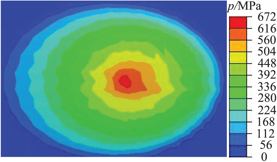
Contact pressure cloud diagram.

Von Mises stress cloud diagram.

Equivalent plastic strain cloud diagram.
Differences between characteristic parameters obtained using FE model and semi-analytical method.

FE: finite element.
Conclusion
In this article, the contact characteristics of a rigid ellipsoid in direct contact with an elasto-plastic half-space were studied using a semi-analytical method. Using a program written in Fortran language, the contact pressure, equivalent plastic strain, von Mises stress, and residual stress were calculated based on different friction coefficients and analyzed comprehensively. The main conclusions of this article are as follows:
As the friction coefficient is increased at a constant sliding speed, the equivalent plastic strain and von Mises stress increase, and the maximum equivalent plastic strain becomes more prevalent on the surface; however, the residual stress decreases.
The size of the plastic zone does not change as the friction coefficient increases.
The presence of the shear traction force increases the depth of residual dents and the degree of tangential plowing.
The increase of von Mises stress caused by the increase of shear traction produces more plastic deformation and thus may lead to ratcheting of the material under lighter loads. Therefore, by increasing shear traction, the shakedown limit of the material can be reduced.
Footnotes
Appendix 1
Handling Editor: Farzad Ebrahimi
Declaration of conflicting interests
The author(s) declared no potential conflicts of interest with respect to the research, authorship, and/or publication of this article.
Funding
The author(s) disclosed receipt of the following financial support for the research, authorship, and/or publication of this article: The authors gratefully acknowledge the support from the National Science Foundation of China (Grant Nos 51675422 and 51775431) and Shaanxi Province Key Research and Development Foundation of China (Grant No. 2017GY-028).