
Abstract
The control of rail pressure is quite important in the common rail fuel system. Generally, the rail pressure control strategy is a combination of feedforward control and proportional–integral–derivative feedback control. A lumped parameter model of the common rail fuel system is built. Theoretically, the three main factors that affect the rail pressure are engine speed, rail pressure, and fuel injection. With these factors as the control parameters, the feedforward control logic is established. Then, with the basic fuel amount as the proportional–integral–derivative control parameter, the feedback control strategy is improved. The feedforward control is used to determine the basic fuel amount; the proportional–integral–derivative feedback control is used to fine-tune the basic fuel amount based on the deviation of target rail pressure and real rail pressure. Compared with only proportional–integral–derivative feedback control, the computation load of feedback control is reduced and the response speed is increased. In addition, experiments based on a common rail fuel system test rig are completed. The results show that the fuel efficiency of common rail fuel pump decreases with pump speed, and rail pressure increases. The steady-state rail pressure fluctuations are effectively reduced and the dynamic control precision of the common rail fuel system increases when the optimized control method is adopted.
Keywords
Introduction
The fuel system is one of the most important parts for an advanced low-emission diesel engine. The electronic control module of the fuel system is essential for a diesel engine. 1 Currently, the common rail (CR) fuel system is one of the most widely employed electronic control fuel systems benefiting the diesel engine to satisfy the strict emission regulations. 2 Rail pressure is a major control parameter because it affects the injection characteristics directly.3–5 The level of rail pressure determines the injection pressure and the injection amount per cycle. In addition, the stability and transient response of rail pressure has great influence on the engine performance factors such as starting, idling, acceleration, fuel economy, and emissions. 6
In the CR fuel system, the rail pressure is controlled by adjusting a flow measurement unit (Meun valve) of the fuel pump. Figure 1 shows the basic diagram of the rail pressure control process for the high-pressure CR fuel system. Generally, during diesel engine operation, the control system acquires the required fuel injection amount by means of a lookup table in response to the signals of engine speed and pedal opening. Then, the control system confirms the target control value of rail pressure paim in response to the fuel injection amount and engine speed. Meanwhile, the real rail pressure of the fuel system pre is acquired by the pressure sensor in the rail. The electronic control module of the fuel system compares the difference between pre and paim and then calculates the resultant electric current of the Meun valve. 7
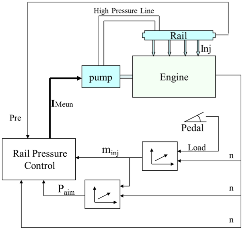
Basic principle of rail pressure control for high-pressure common rail fuel system.
Researchers have done much research on the rail pressure control algorithm for the CR fuel system. Chatlatanagulchai et al. 8 analyzed the rail pressure in the Nichols diagram based on the quantitative feedback theory (QFT), so as to obtain the most robust control effect for the CR diesel engine. In order to reduce the residual pressure, Montanaro et al. 9 proposed a model reference adaptive control (MRAC) algorithm based on a CR mean value model. Chen et al. 10 reported the triple-step method, which is a new nonlinear control method for rail pressure and, by means of this method, the complex and time-consuming calculations in control law are translated into a map and the response speed of the control system is improved. Wang et al. 11 focused on rail pressure control under transient operating conditions, and the change rate and gradient of the rail pressure were used to obtain the target rail pressure step by step.
Along with the continuous improvement of the rail pressure control requirements and the control algorithm, the feedforward control has been introduced into the rail pressure control system, and its employment has become the mainstream direction of rail pressure control. Intended to control the rail pressure, the feedforward control is first set to calculate the basic fuel amount from the fuel pump in response to the engine operation situation (speed and load) and the target rail pressure paim. 12 Figure 2 illustrates the basic logic of rail pressure feedforward control strategy. At this point, the feedback control is mainly used to correct rail pressure fluctuations. The feedforward control quantity and the feedback control quantity are added together to obtain the final fuel amount from the fuel pump, which is then converted to the corresponding electric current of the Meun valve.
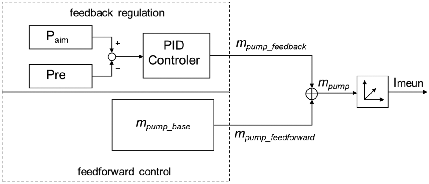
Predictive control and feedback control.
Researchers have carried out some current research on feedforward control. Chatlatanagulchai et al. 13 reported an integrator-augmented sliding mode controller integrating with gain scheduling and feedforward term to make the CR pressure control accurately. Seungwoo et al. 14 developed a feedforward–feedback control algorithm. Their feedforward control algorithm is derived from an empirical model of the relationship between the driving current of the pressure control valve and the rail pressure. Liu et al. 15 proposed a feedforward–feedback controller based on a nonlinear model of the fuel rail system, where nominal feedforward control is built based on the differential flatness control technique.
Although the above research involves factors that contribute to optimizing rail pressure control, the main factors affecting rail pressure have not been directly studied within the high-pressure CR fuel system itself. For feedforward–feedback control method, the issue of rail pressure control lies in precisely calculating the fuel amount from pump of feedforward control. 16 The more precise the calculation of feedforward control is, the better the feedback control is; improvements appear in the control system’s performance related to micro-control and rapid response. Furthermore, overall system stability depends on the feedback regulation, especially the parameters of the proportional–integral–derivative (PID) controller. This article focuses on the fuel system. A lumped parameter model of the CR fuel system is built to analyze the causes of rail pressure build-up, and the main factors causing the change of rail pressure are extracted. Then, a feedforward algorithm is established by evaluating the feedforward characteristics. At the same time, a more accurate feedback control algorithm is proposed. The control strategy of the high-pressure CR fuel system is completed and verified by experiments.
Theoretical analysis of the CR fuel system
First, the CR fuel system is modeled. In this model, the CR fuel system is simply regarded as a lumped system which concludes an input section and an output section. Taking the high-pressure CR as the study object, the input section refers to fuel from the fuel pump, while the output section is fuel out of the fuel injectors (including injection and leakage) and the static leakage of the outlet valve. Figure 3 shows the simplified model of the CR fuel system.

Simplified model of the CR fuel system.
In the CR, the fuel pressure is greater than 200 MPa, which requires that the fuel must be considered as a compressible fluid. Assuming that the pressure distribution of the compressed fuel in the CR is uniform, according to the definition of fuel elastic modulus, we obtain
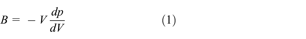
where B is the elastic modulus, V is the CR control volume, and p is the rail pressure.
Then, according to Figure 3 and the CR fuel continuity equation, we obtain

where
According to equation (2), the pressure in the CR is mainly determined by
Calculation of dynamic input of CR
The dynamic input of the CR is the actual pump quantity of the high-pressure fuel pump which comes from the pump quantity of the low-pressure fuel pump under the condition that the leakage of the inlet valve, outlet valve, and the plunger chamber is not ignored.
Then, we obtain

where

where
When the pressure of the low-pressure fuel line is greater than that of the plunger chamber, the fuel in the low-pressure fuel pump enters the plunger chamber through an inlet valve, and we obtain

where
When the inlet valve is closed, the leakage of the inlet valve is as follows


where p is the rail pressure (Pa),
The leakage of the plunger chamber is as follows


where
The leakage of the outlet valve is as follows


where
By incorporating equations (5)–(9) into equation (4), we obtain


where

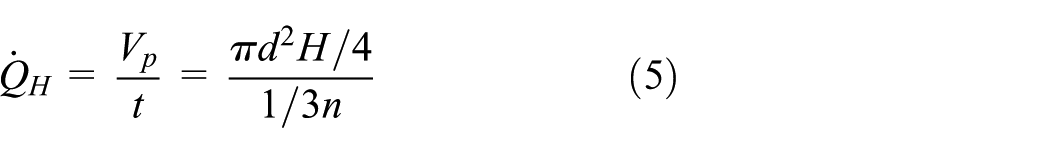
Then, the mass of the fuel entering the high-pressure rail in time t is as follows

According to the calculations above, under the condition that the low-pressure fuel line is determined and that the fuel system geometry structure is invariable, the fuel pump efficiency is mainly related to the fuel pump speed and fuel rail pressure, as is the mass of the fuel entering the high-pressure rail. Specifically, the dynamic input of rail pressure can be characterized by engine speed and rail pressure.
Fuel elastic modulus
According to Lino et al., 12 the fitting formula for the fuel elastic modulus is as follows

where

According to the above formula, the fuel elastic modulus B is mainly characterized by rail pressure.
Calculation of the dynamic output of CR
The dynamic output of CR is the fuel out of the fuel injectors, including fuel injection quantity and injector leakage. Injector leakage is due to less coupling between precision parts but, for a properly manufactured fuel injector, injector leakage is minuscule if present and can be ignored compared with the total amount of fuel injection.
The quantity of the fuel in the injector is realized according to variation in accordance with the working conditions of the engine, and the control system is changed in accordance with the rail pressure and the charging time. Therefore, the injection quantity of the injector is a separate variable,
Thus, we obtain

Then, the mass of the fuel out of the fuel injector in time t is as follows

Therefore, the dynamic output of the CR can be characterized by the fuel injection quantity of the injector and the engine speed.
Calculation of static leakage of the outlet valve
With the rail pressure in the steady state, when the rail pressure is too high and the pressure in the plunger chamber is too low, the fuel in the CR enters the plunger chamber through the outlet valve, which causes static leakage from the outlet valve, which is part of the high-pressure differential clearance leakage.
Because the gap between the matched set is very small, the fuel viscosity also affects the movement of the fuel. Generally, there are two categories of fuel movement within the narrow passage: one is called Poiseuille flow, caused by pressure difference, and the other is called Couette flow, induced by the relative movement of the gap walls. The combination of these two flows is Couette–Poiseuille flow. Movements of leakage of the outlet valve induce Couette–Poiseuille flow in the space between the cylindrical surfaces of the axle and bore. Figure 4 shows the model of flow in the narrow gap between the matched surfaces of axle and bore. In Figure 4, Dp is the diameter of the control piston, Db is the diameter of the bore, Vp is the velocity of the control piston’s valve body, Vb is the velocity of the control piston’s inner wall, pin is the pressure in front of the control piston, and pout is the pressure in the back of the control piston.

Flow model in gap between the matched surfaces of axle and bore.
In this model, the flow between the gaps is considered to be stable laminar flow. Therefore, the movement of this flow can be illustrated by equation (16) according to the Navier–Strokes equation

where v is the velocity of the axial x component and p is the pressure of the fluid.
If equation (16) is integral, then we obtain

The boundary condition in equation (17) is as follows

With the given v and y values of boundary condition, the constant coefficients a and b may be solved. Substituting the values of a and b into equation (17), we obtain


For the pressure gradient along the sealing surface of the outlet valve, we assume that its longitudinal distribution is linear. Then, the pressure gradient is expressed as follows

where
The flow rate between the gaps of the outlet valve matched set is defined as follows

With the combination of equations (18)–(20), equation (21) is solved and expressed as

From equation (22), we can see that the leakage
Then, we obtain

where

Then, the mass of the fuel of the static leakage of the outlet valve in time t is as follows

According to equation (24), the static leakage of the outlet valve is mainly determined by the rail pressure and the engine speed. Therefore, the static leakage of the outlet valve can be characterized by rail pressure and engine speed.
In summary, by incorporating equations (11), (13), (14), and (23) into equation (2), we obtain
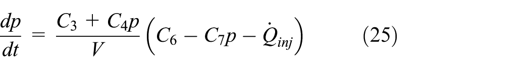
where

Then, we obtain

According to equation (26), we know that the stability of the rail pressure is mainly affected by the influence factors such as rail pressure (p), engine speed (n), and fuel injection quantity of the injector
The purpose of rail pressure control is to obtain stable rail pressure and minimize rail pressure fluctuation. However, the fuel pressure in the CR is determined by the basic fuel amount from the high-pressure fuel pump. The issue of the feedforward control lies in precisely calculating the basic fuel amount from the pump which is the fuel amount that the CR needed, namely, the leakage of the high-pressure fuel pump and the fuel out of the CR. Consequently, the basic fuel amount is as follows

where
According to equation (27), the basic fuel amount of feedforward control includes two parts: one is the leakage of the CR and high-pressure fuel pump and the other is the mass of the fuel out of the fuel injectors.
Control method
Feedforward control
According to section “Theoretical analysis of the CR fuel system,” the basic fuel amount of feedforward control includes two parts: one is the leakage of the CR and high-pressure fuel pump and the other is the mass of the fuel out of the fuel injectors. The leakage of the CR and high-pressure fuel pump is determined by rail pressure and engine speed. The mass of the fuel out of the fuel injectors is a separate variable. The feedforward control principle is shown in Figure 5. Rail pressure, engine speed, and fuel injection are set to the input values for the control system. The fuel leakage is obtained by means of a lookup table based on the signals of engine speed and rail pressure. Finally, fuel leakage and fuel injection are added together to obtain the basic fuel amount.
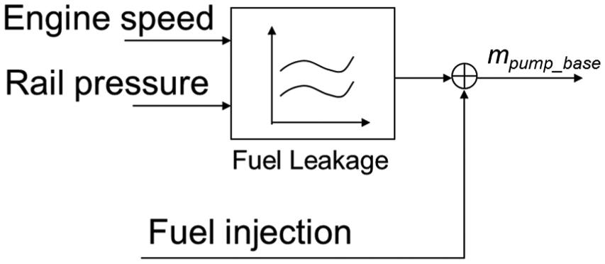
Feedforward control logic.
The feedforward reference quantity is determined by the pumping characteristics, and it can be acquired according to the steady-state open-loop test on the fuel pump test bench. According to the software architecture provided by the algorithm proposed in this article, taking the minimum pressure fluctuation as a target, the control map can be completed under the fuel pump test and, finally, the feedforward reference quantity is determined.
Feedback control
The PID control method is adopted in the closed-loop control of the rail pressure. The difference between the real value of rail pressure pre and the objective value paim is set to be the input value of PID control. For the PID control method, the PID algorithm is suitable for the linear model. If the model is not linear, the PID control parameters vary under different control conditions. Actually, the CR fuel system is exactly a nonlinear system. Therefore, there must be an amendment to the PID control parameter. To address this issue of feedback control, we focus on the PID amendment algorithm for this model.
The adjustment and amendment of the PID control parameters are relative to the corresponding influence factors for rail pressure in the CR fuel system. There are mainly three influence factors (n,

Feedback control logic.
PID feedback control is used to provide dynamic correction, and the determination of its parameters is also carried out on the fuel pump test bench. According to the software architecture provided by the algorithm proposed in this article, taking the minimum pressure fluctuation as a target, the PID control parameters under different conditions can be determined based on the general PID amendment algorithm.
As a result, the control algorithm is realized by feedforward control and feedback control. The optimized rail pressure control principle is shown in Figure 7.

Optimized rail pressure control principle.
Experimental setup
In order to research the pumping characteristics and verify the control strategy, the experiments based on a CR fuel system test rig are completed. The schematic of the experimental setup is shown in Figure 8. In the test rig, the high-pressure fuel pump is driven by an electric motor. The control system is a dSPACE control prototype which is a combination of MicroAutoBox and RapidPro. The cycle fuel injection is metered and tested by an Emerson CFM025. The tested CR fuel system components are presented in Table 1.

Schematic of the experimental setup.
Test apparatus.
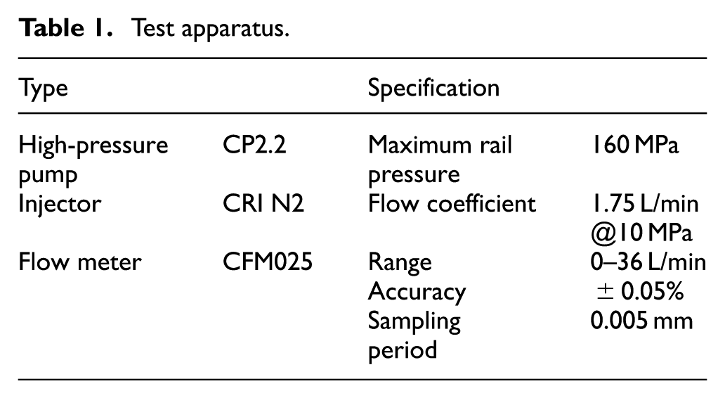
The test of pumping characteristics of high-pressure fuel pump is carried out under different working conditions (different rail pressures and speeds). The pump speed is fixed at even speeds, that is, 500, 700, 800, 1000, 1200, 1300, and 1400 r/min. Then we measure the actual pump pressure of the high-pressure fuel pump under the conditions of target rail pressures at 50, 80, 100, 120, 140, and 160 MPa. In order to ensure the reliability of the test data, each condition is measured three times. The average fuel supply per cycle is calculated by theoretical calculation. The fuel pump efficiency characteristics of the fuel pump are further analyzed according to the test data.
We need a verification test of the rail pressure control method, under the condition of the pump running at 950 r/min and the maximum fuel injection amount per cycle being maintained at 230 mg. To achieve this, steady-state and dynamic tests of two control methods, the traditional PID control and the optimized rail pressure control (the feedforward and PID combination) methods, are carried out.
Results and discussion
Test results of fuel pump efficiency
Figure 9 shows the fuel pump efficiency results with the increase of target rail pressure at different pump speeds.

The results of fuel pump efficiency changes with rail pressure.
Figure 9 shows that the fuel pump efficiency tends to decrease with the increase of target rail pressure under the condition of the pump speed remaining constant. Under the condition of the target rail pressure remaining constant, the fuel pump efficiency tends to decrease with the increase of the pump speed. This fact indicates that the fuel pump efficiency is inversely proportional to the pump speed and the target rail pressure, which is consistent with the results of the theoretical analysis equation (10). Moreover, because the theoretical pump quantity of the high-pressure fuel pump is fixed under the fixed CR fuel system and conditions, the actual pump quantity of the high-pressure fuel pump is directly proportional to the fuel pump efficiency. The actual pump quantity of the high-pressure fuel pump is also inversely proportional to the pump speed and the target rail pressure. As a result, the dynamic input of rail pressure, which is the actual pump quantity of the high-pressure fuel pump, can be characterized by engine speed and rail pressure.
Test results of the control effect
Figure 10 shows the test results of the stable operation state, while the dynamic operation state test results are illustrated in Figure 11.

Test results of stable state: (a) paim = 100 MPa, (b) paim = 120 MPa, (c) paim = 140 MPa, and (d) paim = 160 MPa.

Test results of dynamic state: (a) paim = 140–160 MPa and (b) paim = 160–140 MPa.
Figure 10 shows the control effects with different paim values such as 100, 120, 140, and 160 MPa. It can be seen that those curves of single PID for different paim are always in relatively large oscillation. Obviously, the fluctuation range of 100 MPa is about ±2 MPa, and that of 160 MPa is about ±4 MPa. The single PID control completes closed-loop compensation regulation according to error difference, the adjustment error of which is very large, and the amount of calculation is increased accordingly making it not easy to keep the control within a quite small oscillation. However, it is possible to reduce this oscillation after introducing the feedforward control together with the PID control. Thus, the curves of the optimized rail pressure control method are markedly flat, with less oscillation, as shown in Figure 10, and the fluctuation range of 100 and 160 MPa is about ±0.3 MPa, which can be ignored.
According to Figure 11, in the dynamic state, under the condition of target rail pressure raising from 140 to 160 MPa, the rail pressure increases first and then remains stable in both of the control strategies; as for the pressure decreasing from 160 to 140 MPa, the rail pressure decreases first and then remains stable. Nevertheless, the feedforward control provides the system with much more precise feedforward control, and thus the dynamic regulation is improved and the time for the system to become stable is shortened. Therefore, this optimized rail pressure control method, PID plus feedforward, shows good stability, the dynamic overshoot of which is decreased about 7 MPa and the time for the system to become stable is shortened 0.05 s.
Conclusion
In this article, the lumped parameter model of the high-pressure CR fuel system is established, the main factors that affect the rail pressure are analyzed, and the rail pressure control algorithm is optimized, namely, the feedforward and PID combination. The conclusions can be summarized as follows:
Based on the pumping characteristics, the main factors that affect the rail pressure are rail pressure, engine speed, and fuel injection quantity of the injector, according to the theoretical analysis. Also, the experimental results show that the fuel pump efficiency is inversely proportional to the pump speed and the target rail pressure.
The feedforward control is established based on the leakage of the CR and high-pressure fuel pump and the mass of the fuel out of the fuel injectors. The leakage is obtained by means of looking up a lookup table drawn from the signals of engine speed and rail pressure. Meanwhile, the feedback control based on the basic fuel amount as the input of the PID amendment algorithm is established. The experimental results show that the optimized control method can effectively reduce rail pressure fluctuation and achieve better rail pressure control than the traditional PID control method.
Footnotes
Handling Editor: Anand Thite
Declaration of conflicting interests
The author(s) declared no potential conflicts of interest with respect to the research, authorship, and/or publication of this article.
Funding
The author(s) disclosed receipt of the following financial support for the research, authorship, and/or publication of this article: We gratefully acknowledge the financial support for this work from the National Natural Science Foundation (91641106) and the Beijing Municipal Natural Science Foundation (3172007). In addition, we acknowledge the Collaborative Innovation Center of Electric Vehicles in Beijing and Beijing University of Technology for their financial support to this work.