
Abstract
The main aim of this study was to explore the safety differences when using aluminum alloy and three different fiber reinforced composites as material for the cockpit and fuselage of light aircraft under crash landing. In accordance with the cockpit reduction amount stipulated by MIL-STD-1290A in which the reducing rates in all directions cannot exceed 15%, this study established the safety zones of impact speeds and impact angles. The overall safety zones of the carbon fiber reinforced composites and glass fiber reinforced composites cockpits were higher than that of the aluminum alloy cockpit by 38.56% and 32.12%, respectively. Among the four different fuselage materials, when carbon fiber reinforced composites was used as the cockpit material, except that the reducing rate for the crashing in the Y direction was slightly higher than the aluminum alloy cockpit, the reducing rate in the X direction and the inclined beam A direction during crashes were less than other materials, and the safety of its overall cockpit was also the most superior to other materials. The energy absorption capability of the aluminum alloy fuselage was better than the fuselages of all composite materials.
Introduction
Airplane crashworthiness is primarily defined as the capability of an airplane’s overall system to provide protection for passengers from fatal or serious injury in an event of airplane crash accident. The most important cause of casualties in passengers in an airplane crash is usually that the impact force causes the crushing of cabin, resulting in direct impact on the passengers or obstruction on the escape path, and excessive energy generated by the impact exceeds the human tolerance.
With the economic factors and technological advancement, composite materials are abundantly used as structural materials of aviation. However, most of the composites are classified as brittle materials, which is quite different from the highly ductile materials of traditional aluminum alloy during dynamic impact. The energy absorption capacity during a crash will directly influence the damage level for passengers. On the other hand, due to the different structural design in the airframes of rotorcrafts, small airplanes, and large airplanes, the mechanisms of crashworthiness and energy absorption are different. Because of the space constraints, rotorcrafts and small airplanes can only rely on the fuselage, floor, seats, and landing gear to withstand the absorption of impact energy. Large airplanes have floor, sub-floor, and a strong support structure, which are more effective in absorbing the impact energy during a crash event. Therefore, in an event of falling accident, the survivability of passengers in different types of airplane is also different.
In the 1970s, the US Army had studied the injuries caused by crash accidents of rotorcrafts and pointed out that if the initial design of the airplane considers crash safety, of which 92.8% of the crash accidents would have the survivable or partially survivable possibilities. In 2004, FAA added the Light Sport Aircraft (LSA) category that this type of airplane must comply with ASTM F2245 standards.1,2 Because of the rapid growth of the LSA market in the United States, the statistics of FAA showed that there were a total of 6811 LSAs in the United States at the end of 2008. Forecasting under the assumption of annual growth at about 825 airplanes, it is predicted that there will be 16,311 LSA by 2030. 3 In the investigation report of civil aviation accidents published by NTSB in 2011, it is pointed out that there are a total of 1553 cases of accidents statistically attributable to the 14 CFR Parts 121, 135, and Part 91; of these General Aviation (GA) aircraft has accounted for 1469 cases (95%). 4 Among the fatal accidents, GA has accounted for 92%; of these personal flights with fixed wing is the most. To reduce the fatality rate of passengers in airplane accidents, European Vehicle Passive Safety Network 25 (EVPSN II) proposed that the concept of Total Aircraft Crashworthiness and Societal Safety (TACASS) must be promoted. It is also mainly necessary to integrate the concept of crashworthiness into the initial design of airplane. In 2013, the Ministry of Economy Affairs of Germany funded the research project on cabin safety for light aircraft (Safety Box). 6 It main objective is to provide passengers with overall protective measures during a plane crash, including a better energy absorption mechanism and a more robust structure. As we know, GA is growing rapidly in the global airplane market, but safety considerations are still the main factors hindering the vigorous development. Due to the simple structure and lack of crashworthiness design in light airplanes, especially the considerations on impact energy absorption, an accident event usually causes significant harm to crews. The main aim of this study is to explore the safety of using different composites as structural materials of fuselage for light aircraft under different crashing speeds and angles.
Relevant studies
The MIL-STD-1290A 7 was the crashworthiness research of the US army for light fixed and rotary-wing airplane. As the minimum safe impact criteria, this standard has mainly established the crashing velocity along the direction of fuselage to be 12.19 m/s, the vertical crashing velocity of fuselage to be 12.80 m/s, and the reducing rates in all directions of passenger compartment should be not more than 15%. This standard mainly requires taking the strength value and the amount of compression of fuselage into consideration. The subsequent publication by the ACSDG engages a wider range of crashworthiness exploration, covering issues such as the overall energy absorption structure of fuselage and the impact resistance of composite fuselage. 8 AGATE consider two to six-seater airplanes made of full composite materials with single engine and a maximum airplane weight of 6000 lb. as research objects.9,10 The research parameters used by AGATE for small airplane colliding onto the ground are a nose-down angle of 30o and Vso.
The energy absorption systems for light airplane include the seats, restraint systems, landing gear, and, most importantly, the fuselage structure. Chen et al. 11 used finite element analysis software to analyze and compare the static and dynamic loading circumstances for landing gear of LSA using materials such as aluminum alloys, glass fiber-reinforced composites (GFRP) and carbon fiber-reinforced composites (CFRP). The study also simultaneously explored the maximum stress and deformation of landing gears of different shapes (including leaf/plate, cylinder, and tube). Under impact loading, the maximum stress undertaken by the cylindrical CFRP landing gear was the lowest. Hooper et al. 10 used reinforcements for the fuselage longerons and the spar web to increase the strengths in the cockpit, so that the stiffness of the front fuselage can be enhanced vertically and horizontally. Europe’s aerospace industry also recognizes the importance of composite materials as the main structural material for airplanes, and established the Commercial Aircraft-Design for Crash Survivability (CRASURV) in 1996–1999 to engage in the safety research of composite material airframe structures under situations of survivable crashing. The CRASURV project was involved in the crashworthiness research of composite fuselage for NH 90 helicopter and ATR 42 commuter airplane.12,13 Wiggenraad et al. 13 pointed out that the sine-wave beam structures fabricated using carbon fiber and aramid fiber composite materials yielded good results under the vertical impact experiment at a speed of 7 m/s. The report also explained that the carbon fiber composite is used mainly because of its high strength and the capability of energy absorption, while the aramid fiber can maintain the structural integrity of the structure after crashing. Heimbs et al. 14 investigated the composite z-struts made from 0°/± 45° carbon fiber/PEEK as the core and outside layer of glass fibers to improve the floor support of commercial airplanes.
Traditional airplanes are mainly made of metallic materials; when external force is loaded, the resulting local plastic deformation (e.g. folding) absorbs the energy. In Europe and the United States, using composite materials to reduce airframe weight has become an inevitable aspect in aircraft design. In 2001, Aerospool s.r.o. obtained the EU ultra-light aircraft certification for the two-seater WT9 Dynamic, in which the fuselage is manufactured using multilayered CFRP, and the aramid fiber is used as the cockpit skin to improve its crashworthiness. Bossak and Kaczkowski 15 conducted a crash-landing simulation of a four-seater all-composite small airplane (PZL I-23) developed in Poland. The main structure of this type of airplane is a sandwich structure of CFRP/GFRP, and the aramid fibers are used as the main honeycomb structure.
Although composite materials have been proven to be effective structural materials and are widely used by the aviation industry, their capabilities of energy absorption remain to be continuously researched. This is mainly due to the lack of consistent experimental standard for the measurement of energy absorption in the composite material specimens.16–19 Composite materials also evolve as different energy absorption structures, such as sandwich, honeycomb, and foam. 20 On the other hand, composite materials are considered to be lighter than the metal materials, and therefore, they have good specific energy absorption (SEA). In the 1980s, FAA and NASA began engaging in the Crash Dynamics Research Development Program on airplanes in the transportation category (e.g. B707 and B720). 21 During 1990–2000, a 10-m-long B737 fuselage was used to conduct a 9.1 m/s drop-off test at a height of 4.27 m to study the interaction between fuselage and floor structure during a crash landing. 22 Currently, there are various views on using fiber-reinforced composite materials to enhance the ability of aircraft to resist an impact or absorb impact energy.23,24 Mou et al. 25 used Hypermesh and LS-DYNA to study a crashworthiness simulation on an aluminum alloy cabin and fuselage with a skin of composite materials. Many investigations use composite materials to improve the energy absorption capability for various structures as well as civil aircraft fuselage under impact loading.26–34
Many studies have proposed experimental methods for determining the absorbed energy of composite materials using different specimens with different shapes as well as various impact speeds.16,35 Feindler et al. 18 used a compressive rate of 0.25 mm/s to test CFRP specimens in omega-shaped and plate-shaped specimens with three different laminate layups (45° and 0°). They pointed out that the energy absorption capabilities of CFRP and aluminum alloy under loading are not the same. They also reported that the SEA values of CFRP are more than twice as high as those of aluminum alloys.
Since there are as yet no consistent standards or appropriate design criteria for tests of the impact resistance and energy absorption of composite materials, most composite fuselage crash-landing simulations or experimental research still take the fuselage segment or the entire plane as a basis.36,37 In the 1990s, EU began the Crashworthiness for Commercial Aircraft program; dynamic tests on the fuselage structure of A320 were used to improve the numerical simulation results. Although the current simulation technology of composite materials in the impact energy is not completely consistent with the experimental results, continuous research and accumulated data can effectively reduce the time and cost performed by actual fuselage crashing tests.
Simulation and analysis
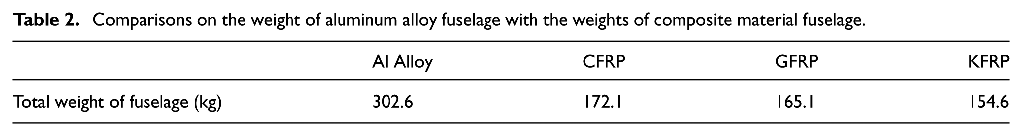
The three-dimensional (3D) fuselage model of a Zenith STOL CH 701 (as shown in Figure 1) was constructed using Pro/E and simulation analyses were performed using the finite element analysis software ABAQUS/Explicit. When the cockpit and fuselage perform the crash-landing simulation, the amount of reduction of the cockpit during a crash along the fuselage (X direction), the vertical direction (Y direction), and along the inclined beam of the cockpit (A direction) would be calculated, as shown in Figure 2. The material parameters of the aluminum alloy, CFRP, GFRP, and Kevlar fiber reinforced composites (KFRP) used in this study are listed in Table 1. In this study, all three composite materials were set to be 0o lamina. Table 2 shows the weights of the four fuselage materials. The weights are the total weight of the engine frame, firewall, cockpit, and fuselage frame and not including the weight of the landing gear, wings, vertical and horizontal rudders, and skins.

3D model of the cockpit and fuselage of CH 701.

Schematic diagram on the X direction, Y direction, and inclined beam A direction of the cockpit in CH 701.
Material parameters of aluminum alloy and composite materials.

Comparisons on the weight of aluminum alloy fuselage with the weights of composite material fuselage.
Concerning the boundary conditions for the simulations, we used those stipulated in the AGATE and ASTM (i.e. an impact angle of 30° and an impact speed of 1.3 Vso) to perform the crashworthiness of light aircraft subjected to impact loading. The stall speed (Vso) of STOL CH 701 during flap development is 27 kts. From this number, the impact speed of STOL CH 701 can be calculated as 18.05 m/s. In addition, we adopted the MIL-STD-1290A as the minimum safety requirement, which requires passenger compartment reduction amount of no more than 15% when aircraft are subjected to impact loading. In this article, the reducing rate (%) is defined as follows: the compression amount in the X direction, in which the change in the length from the most frontward crashing point of fuselage to the fuselage cockpit is divided by the original length of the fuselage; the compression amount in the Y direction, in which the change in height from the highest point to the lowest point of the cockpit is divided by the original length value of the fuselage in the Y direction; the compression amount in the direction of the inclined beam A, which is the ratio of the change in the length of the inclined beam to the original length. In this simulation, the selected element type for the fuselage mesh is SC8R (8-node quadrilateral elements). In the fuselage model after mesh segmentation, there are a total of 345,162 nodes (nodes) and 253,439 elements (elements).
In this study, ABAQUS/Explicit was used for the output of each energy component after simulation to validate the reasonableness of the dynamic simulation results. For the samples of this study in the process of crashing to the ground, the kinetic energy (EKE) decreased gradually with time and tended to be stable after collision; the internal energy (EI) increased with time, and the total energy (Etotal) was conserved. Another parameter that can confirm the correctness of the simulation setting is the artificial strain energy (EA). The artificial strain energy was used to validate the reasonable response generated by the model meshing under the loading condition. The artificial strain energy in ABAQUS/Explicit was mainly used to suppress and avoid the generation of the hourglass phenomenon. Usually, the artificial strain energy must be less than 1%–2% of the internal energy (EI). Figure 3 shows the energy variation diagram for the aluminum alloy 6061T6 fuselage at an impact speed of 18.05 m/s and an impact angle of 30°. From Figure 3, it is found that the kinetic energy was reduced during the impact, the internal energy was increased and the total energy remained constant; the artificial strain energy was less than 2% of the internal energy. The results show the correctness of the parameter setting for this dynamic simulation and the reasonableness of the results. In the crash-landing simulation results of the fuselage structures with different fiber composite materials, the energy variation results are similar to those seen in the crash-landing plot patterns of the aluminum alloy fuselage. The prediction of composite failure as analyzed by Abaqus/Standard or Abaqus/Explicit includes the following four types of modes: Hashin’s criteria, traction separation laws, user material (UMAT), and vectorized user material (VUMAT). Hashin is mainly used to evaluate the failure of single-lamina composite materials. Traction separation laws are mainly used to evaluate the failure of multi-laminate composite materials. Both of these modes can be used directly to input relevant material parameters for subsequent computation. UMAT and VUMAT are employed when using Abaqus/Standard and Abaqus/Explicit, to analyze the destruction mechanics of multi-laminate composites using simulations. We have previously used the Hashin’s criteria options to compare the differences in loading, deformations, and energy absorptions during impact for a single-lamina composite structure in cases that both take consideration of failure mode and do not take consideration of failure mode; however, the results indicated that no significant difference exists. As this study mainly compares the impact response of different fiber composite materials (single lamina at 0o), the failure mode of composites has not been taken into consideration.

Energy variation of aluminum alloy fuselage during the crashing.
Results and discussions
Table 3 shows the energy variation of different cockpit materials at an impact speed at 18.05 m/s and an impact angle of 30°. Here, the change in the EI during the crashing is the impact energy absorbed by the cockpit and fuselage structure, and SEA is defined as the EI absorption amount per unit weight. Table 3 shows that the EI variation of the aluminum alloy fuselage was greater than those of the fuselages made of composite materials by about 1.80–2.17 times. However, taking consideration of the weight factor, the SEA of the aluminum alloy fuselage is also higher than those of the fuselages made of composite materials by about 59.70%–72.58%.
Comparisons of the energy of cockpits with different materials at an impact speed of 18.05 m/s and an impact angle of 30°.

Figure 4 shows schematic diagrams of the destruction by compression amount in aluminum alloy and composite fuselage at a fixed impact speed (18.05 m/s) and different impact angles of 20o–50o. The diagrams mainly describe that the major damage positions of a light aircraft structure under the impact situation are the junction between the engine frame and firewall and the junction of the firewall and fuselage (i.e. the X direction and inclined beam A direction). Figure 5 shows the relationship of cockpit reducing rate with different impact angles for the aluminum alloy and composite materials fuselages under a fixed impact speed of 18.05 m/s. Figure 6 shows the relationship of cockpit reducing rate with different impact speeds for the aluminum alloy and composite materials fuselage at fixed impact angle of 30°.

Deformation of the aluminum alloy fuselage at different impact angles for the aluminum alloy and composite materials fuselage and fixed impact speed of 18.05 m/s. (a) Impact angle of 20°. (b) Impact angle of 30°. (c) Impact angle of 40°. (d) Impact angle of 50°.

Relationship of cockpit reducing rate with different impact angles for the aluminum alloy and composite materials fuselage at fixed impact speed of 18.05 m/s. (a) aluminum alloy fuselage. (b) CFRP fuselage. (c) GFRP fuselage. (d) KFRP fuselage.

Relationship of cockpit reducing rate with different impact speeds for the aluminum alloy and composite materials fuselage at fixed impact angle of 30°. (a) aluminum alloy fuselage. (b) CFRP fuselage. (c) GFRP fuselage. (d) KFRP fuselage.
Figure 7 shows the relationship of cockpit reducing rate with respect to different impact speeds (9.03–90.30 m/s) for fuselages of the four different materials at a fixed impact angle of 30°. As revealed from the plots: (1) the amount of compression at different impact speeds was the largest for the inclined beam A direction; for the aluminum alloy fuselage, the deformation amount had exceeded the safety limit of 15% at an impact speed of 44.05 m/s, whereas the best CFRP fuselage among the four materials exceeded the safety limit of 15% at 67.13 m/s only; (2) in the X direction, the aluminum alloy fuselage exceeded the safe boundary line at an impact speed of 56 m/s; the amounts of the fuselage deformation for three types of composite materials were approximately 10%–12% at an impact speed of 70 m/s; the deformation amount for CFRP had not exceeded the safety limit of 15% at the interval of this impact speed; and (3) the deformations in the Y direction for fuselages of all four different materials did not exceed 10%.

Relationship of cockpit reducing rate with different impact speeds for fuselages of different materials at fixed impact angle of 30°. (a) X direction. (b) Y direction. (c) A direction.
Figure 8 shows the relationship of cockpit reducing rate with different impact angles of 0°–90° for fuselages of four different materials at a fixed impact speed of 18.05 m/s. The plots revealed the following: (1) the impact angles were more influential on the reducing rate in the X direction; (2) in the X direction, the reducing rate of aluminum alloy fuselage reached the limit of 15% at a impact angle of 57°; however, the maximum reducing rate for fuselages of the three composite materials in this direction also was only 4.72%; (3) in the inclined beam A direction, the maximum reducing rate of the aluminum alloy and KFRP fuselages were 7.32% and 7.81%, respectively, whereas the maximum reducing rate for the CFRP fuselage was only 3.08%; and (4) the maximum reducing rate for fuselages of all four types of materials in the Y direction were within 2.44%.

Relationship of cockpit reducing rate with different impact angles for fuselages of different materials at fixed impact speed of 18.05 m/s. (a) X direction. (b) Y direction. (c) A direction.
Comparing Figures 7 and 8, we found that the influence of impact speed on the cockpit reducing rate was significantly greater than the effect of impact angle. The reducing rates of cockpit of four different materials in the inclined beam A direction, at higher impact speed were significantly higher than the deformation amounts in other directions, and were higher than the deformations during the crashing at different angles and a fixed speed. Among the crashes of different speeds and angles, the deformation amounts of cockpits of all four materials in the Y direction were the least.
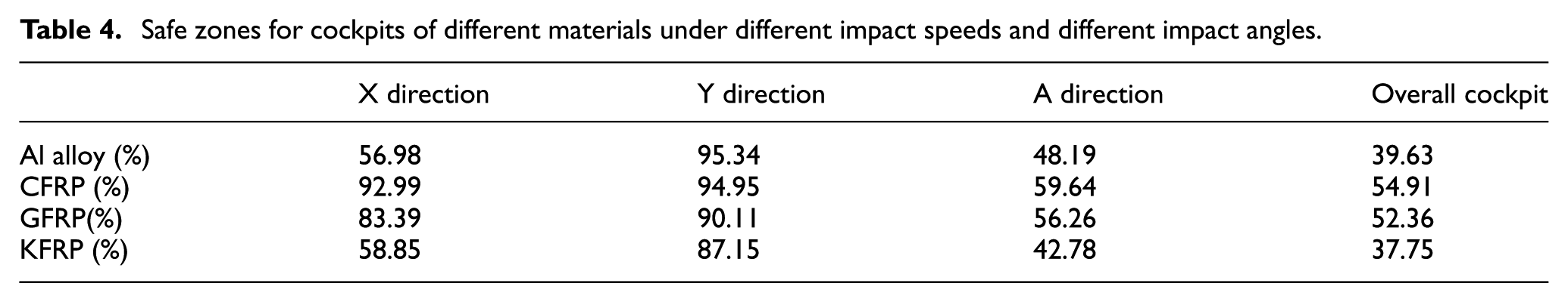
Table 4 shows the cockpit reducing rates in the X direction, the Y direction, and the inclined beam A direction at varying impact speeds (0–90 m/s) and impact angles (0°–90°) in this study. In addition, in accordance with MIL-STD-1290A specifications that the reducing rates of cockpit in all directions must not exceed 15%, the safe zones under different crash-landing situations for four different materials are established (Figure 9). Table 4 reveals the following:
In the X direction of the cockpit, the CFRP fuselage exhibits the best capability to resist deformation, primarily due to its highest strength and El elastic modulus. The safe zone of the GFRP fuselage in the X direction during crashing is slightly less than that of the CFRP fuselage, with a difference of approximately 10%. The KFRP and aluminum alloy fuselages had similar safe zones in the crashing along the X direction.
The deformation amounts of the cockpit in the Y direction when subjected to crashing are the smallest than those in the X direction and the inclined beam A direction, and has the largest safety zone. The deformation in the Y direction is mainly due to the lateral expansion caused by the loads along the axial direction of an airplane during its crash landing; therefore, its influence on the passengers’ safety is lesser. Among the four materials, the aluminum alloy fuselage and the CFRP fuselage have better safety ranges.
Among the three directions, the reducing rate in the direction of inclined beam A plays a critical role during airplane crash landing because the crushing in this direction may cause a collide of the passengers’ heads with the cockpit structure, leading to serious injuries. Among the four materials, CFRP and GFRP have better safe zones, whereas KFRP demonstrates the lowest safe value in this zone.
Summarizing the comparison on the overall safe zones of cockpit, the CFRP and GFRP fuselages show relatively high safety, while the aluminum alloy and KFRP fuselages have similar safe ranges under the crashing situations at different angles and different speeds.
Safe zones for cockpits of different materials under different impact speeds and different impact angles.
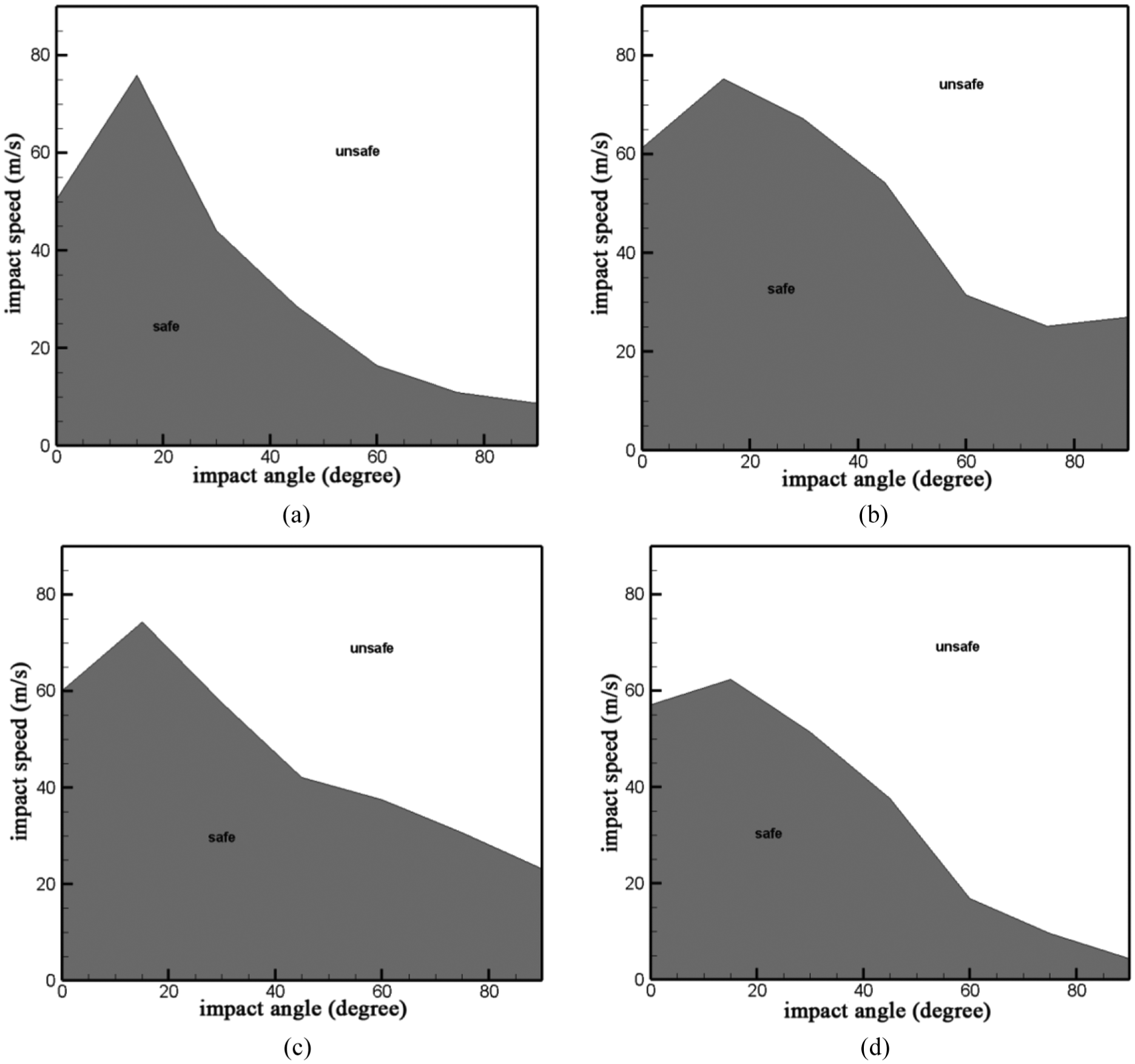
Overall safe zone for the cockpit of aluminum alloy and composite materials fuselage. (a) aluminum alloy fuselage. (b) CFRP fuselage. (c) GFRP fuselage. (d) KFRP fuselage.
Conclusion
Following the safety criteria stipulated by MIL-STD-1290A that the reducing rate in all directions of a cockpit must not exceed 15%, this study mainly compared the crash-landing safety and energy absorption capability for fuselages made of three different fiber composite materials and aluminum alloy material under situations at different impact speeds and impact angles.
The setting of each simulation parameter (e.g. material coefficient, mesh segmentation, impact parameters) in this study is based on the changes in the total energy balance and conservation as well as artificial strain energy (hourglass phenomenon) to validate the simulation results.
When CFRP, GFRP, and KFRP were used as structure materials of light aircraft cockpit and fuselage, the weight of fuselage could be reduced by 43%, 45%, and 49%, respectively, compared with the weight of the aluminum alloy fuselage.
The influence of impact speed for the safety of fuselage was more significant than the effect of impact angle. The reducing rates in fuselages of four different materials in the direction of inclined beam A at different impact speeds were relatively higher than those in the other directions. These reducing rates were also higher than the deformations during crashing at fixed speed with different angles.
Among the four materials, the aluminum alloy cockpit had the best energy absorption capability during impact, which was about twice as high as those in fuselages made of composite materials. While the SEA of the aluminum alloy structure also was higher than those in fuselages of the three composite materials, among the structures in the three composite materials, the energy absorption value and the SEA of CFRP were slightly higher than those of the other two composite materials.
When fuselages of the four different materials were tested at a fixed impact angle (30o) but different impact speeds, the structural component along the inclined beam A direction was critical. Under the safety criteria that the deformation should not exceed 15%, the impact speeds to be tolerated by CFRP, GFRP, and KFRP fuselages were 67.13, 57.63, and 51.39 m/s, respectively. Compared to the critical impact speeds of 44.05 m/s for the aluminum alloy fuselage, these critical speeds increased by 52%, 31%, and 17%, respectively.
Under the situations of a fixed impact speed (18.05 m/s) but different impact angles, the aluminum alloy fuselage exceeded the safety criteria of a 15% reducing rate at an impact angle of 57° in the X direction, but the deformations of the three composite materials were all smaller than 5% under the same crashing conditions. Moreover, at the impact speed of 18.05 m/s with the impact angles of 0°–90°, the GFRP fuselage and the aluminum alloy fuselage had the maximum deformations in the A direction (7.26% and 7.32%, respectively), while the maximum deformation of the CFRP fuselage was only 3.08%.
At different impact angles and impact speeds, the deformation amounts in the fuselage of different materials along the Y direction were smaller than those in the X direction and the inclined beam A direction; all its maximum deformations did not exceed 10%. Therefore, comparing the safe zones of different fuselage materials in different directions, the safe zone ranges of cockpit in the Y direction were the highest than those in the X direction and the inclined beam A direction. The aluminum alloy fuselage had the highest safe zone in the Y direction.
The CFRP fuselage was the best in the cockpit X direction, inclined beam A direction, and the overall cockpit safety. Compared with the safe zone of the aluminum alloy fuselage, the safe zones of the CFRP fuselage in the X direction, the inclined beam A direction, as well as the overall cockpit increased by 63%, 24%, and 39%, respectively.
The GFRP fuselage was slightly lower than the CFRP fuselage in all directions and in the overall safe zone, the difference was within 5%–10%. The performance of the KFRP fuselage was roughly the same as that of the aluminum alloy fuselage, but in the overall safe zone, it was still lower than that of the aluminum alloy fuselage by about 5%.
Footnotes
Handling Editor: Amanda Wu
Declaration of conflicting interests
The author(s) declared no potential conflicts of interest with respect to the research, authorship, and/or publication of this article.
Funding
The author(s) received no financial support for the research, authorship, and/or publication of this article.