
Abstract
Machine tool accuracy analysis has become increasingly important since accuracy as the major parameter of a machine is to a large extent determined by geometric accuracy design. In order to improve the comprehensiveness and veracity of geometric accuracy design, this article proposes an improved geometric error analysis method considering the variety of sensitivities over working space. A multi-rigid-body model which includes cutting tool’s wear-out error and workpiece’s clamping error is established to represent the position relationship of machine tool’s working components. The expression of geometric error is converted from matrix form to screw form through the screw mapping theory, so that rotational error can be expressed and calculated directly like the translational error. Considering motion errors along axes over the whole working space instead of at a fixed position, an improved sensitivity analysis algorithm is conducted to identify, among 38 components of errors increased the variety with tool wear and clamping errors, which of them have a significant impact on four different types of machine errors. Finally, the proposed method was implemented and validated on a horizontal boring machine, and the sensitivity analysis results over working space would offer vital evidence for the machine’s geometric accuracy design.
Keywords
Introduction
Machine tool accuracy analysis has become increasingly important since the demand for high-precision parts is rapidly increasing, and accuracy as the major parameter of a machine is to a large extent determined by geometric accuracy design. Despite the plenty of researches done in recent years, improving geometric accuracy remains to be a popular topic. Geometric accuracy is affected by many types of errors—from the aspect of error property: positioning error, straightness error, pitch error, yaw error, roll error, and squareness error; from the aspect of working components: errors along (about) axis from moving components, errors of cutting tool, fixture, and workpiece. All these errors should be carefully considered during the geometric accuracy design phase.
There are two main ways to improve geometric accuracy of machine tools: (1) improve manufacturing and assembly accuracy of working components. (2) Reduce geometric errors through numerical compensation. Both of them should be concerned during the machine tools’ design phase. Hence, a mathematical model that describes the relationship between geometric error and machining accuracy should be established first. A variety of modeling methods have been presented up to date, such as rigid body kinematics theory, homogeneous transformation matrix (HTM),1–3 Denavit–Hartenberg method,4,5 and screw theory. 6
Some researchers used the model to measure and compensate geometric errors. Raksiri and Parnichkun 7 proposed a cutting-force-induced error estimation by back-propagation neural network determined based on a flat end mill behavior observation and used separately in the cutting-force-induced error compensation model. Uddin et al. 8 presented a simulator of machining geometric errors in five-axis machining by considering the effect of kinematic errors on the three-dimensional interference of the tool, and the workpiece and kinematic errors of a five-axis machining center with tilting rotary table type were first identified by a double ball bar (DBB) method. Okafor and Ertekin 9 used rigid body kinematics and small-angle approximation of the errors to model each slide of the three-axes vertical machining center and predicted machine tool geometric errors as well as thermally induced errors for error compensation. Majda 10 carried out the analytical and experimental examinations for a table in which guide-way geometric errors may result in significant deformations and verified the hypothesis that the deformation of a table may be a significant source of errors in volumetric error models. Jha and Kumar 11 discussed the development of a generalized error model on the effects of geometric errors of the components of the kinematic chain of a machine in the workspace, and the results obtained by this model have been verified experimentally. Andolfatto et al. 12 decompose the geometric errors into two categories: the quasi-static geometric errors independent of the speed of the trajectory and the dynamic geometric errors, dependent on the programmed feed rate and resulting from the machine structure deflection during the acceleration of its axes. Tsutsumi and Saito 13 proposed a calibration method based on the simultaneous four-axis control technique for five-axis control machining centers with a tilting rotary table, and the trajectories were obtained by a mathematical model into which the eight deviations were substituted. Ahn et al. 14 proposed a weighted least squares method to determine the compensation amount to minimize the overall volumetric error in simultaneous cutting and developed a geometric error model using an arch-type, multi-spindle machine tool. Szipka et al. 15 described geometric errors and spatial variation of static stiffness through the synthesis of bottom-up and top-down model building approaches and introduced a characterization of the position and direction dependent static stiffness. Xia et al. 16 proposed a decoupled method based on DBB to identify the geometric errors of rotary axis including both position independent geometric error (PIGE) and position dependent geometric error (PDGE). Xiang and Altintas 17 proposed a method based on screw theory to measure, model, and compensate both PIGEs and PDGEs of five-axis machine tool; the geometric errors of two rotary axes were decoupled into 12 PDGEs and 8 PIGEs to be identified with ball bar measurements. Lee and Yang 18 proposed a method to avoid the effect of translational axis by remaining stationary when identifying geometric errors of the titling rotary table and define the PDGEs as zero at the initial conditions to reduce the effect of positioning errors of ball bar.
Other researchers analyze the influence of geometric errors after establishing the model. Li et al. 19 proposed a multi-body system method to build an error model for a three-axis machining center and identified the key geometric errors affecting the machining accuracy using a combination of matrix differential and experimental test. Hong et al. 20 studied the influence of position-dependent geometric errors of rotary axes on cone frustum machining test in the five-axis machine tool. Sarina et al. 21 proposed an accuracy allocation method through volumetric motion error model, which is based upon the motion error matrix and screw theory, and using a multi-objective nonlinear optimization technique to minimize the manufacturing cost and volumetric motion error twist pitch. Tian et al. 22 developed a linear map between the pose error twist and source errors within machine tool kinematic chains using HTM method and formulated a linear map between the pose error twist and the error intensities, then combine these two models for error separation. Chen et al. 23 established a volumetrical error model of a five-axis machine tool with the configuration of RTTTR (two rotational axes, three translational axes) based on rigid body kinematics and HTM, in which 37 error components are involved and sensitivity analysis of volumetrical error regarding 37 error components is carried out respectively. Wang et al. 24 modeled the error data collected under normal temperature, which is regarded as the basic error with the machine position coordinates based on Newton interpolation method and developed a geometric and thermal error compensation system based on the proposed method. Zhang et al. 25 proposed a compensation implementation technique based upon the function of external machine zero-point shift and Ethernet data communication protocol for machine tools. Hsieh 26 developed a kinematic model to facilitate the design of the helical groove shape combining homogeneous coordinate transformation and conjugate surface theory. Zhang et al. 27 found the motion errors were mainly affected by the geometric errors of guide rails rather than the geometric errors of table and established an approximate model to study the influence of geometric errors of guide rails and table on the motion errors of hydrostatic guideways using the equivalent third power of oil film thickness. Xiang et al. 28 realized volumetric error prediction and compensation models by the forward and inverse kinematics modeling via the screw theory and analyzed key geometric error items of motion axes and their influences on spiral bevel gear tooth performance of a six-axis computer numerical control (CNC) grinding machines. Research mentioned above played an important role in geometric error modeling, compensation, and analysis, but there are some problems remain to be further studied:
Clamping error of workpiece and wear-out error of cutting tool are rarely concerned in geometric error modeling; however, both have great influences on machining accuracy.
Most researches focus on the analysis and compensation of total positioning error (error along X, Y, and Z axes) and neglect the posture error (error about X, Y, and Z axes) which also has an impact on machining accuracy.
Sensitivity analysis of geometric errors is restricted to a certain position, so the main errors affecting geometric accuracy over working space cannot be determined.
Therefore, a novel method is proposed in this article to integrate wear-out error and clamping error into the mathematical model of machine tool and express all geometric errors in six dimensions by screw mapping, then analyze the vital geometric errors affecting geometric accuracy most over working space. The remainder of this article is as follows. The following section briefly introduces two kinds of geometric errors and multi-rigid-body model, then establishes the mathematical model integrated clamping error and wear-out error based on HTM. The next section transforms the geometric error model from matrix form to screw form through a screw mapping method. The subsequent two sections analyze the geometric errors by improved sensitivity analysis, which takes the diversification of the sensitivity coefficient over working space into account, and apply the proposed method to geometric accuracy analysis of a four-axis horizontal boring machine. Finally, the last section concludes this article.
Geometric error model based on multi-rigid-body
Expression of multi-rigid-body system
Machining process of machine tools can be simplified as a moving process in a kinematic chain where the mobile components are regarded as rigid bodies. Geometric errors of moving components mainly consist of two parts:
Location error during manufacturing and assembly process which includes both translational error along axis and rotational error about axis. The translational error can be eliminated by adjusting the coordinate frame to a proper position so that only rotational error regarded as straightness should be concerned in the model which is shown in Figure 1.
Motion error induced by deviation from theoretical position to real position when two rigid bodies are making relative movement. Motion error also takes place in six dimensions: three translational errors along X, Y, and Z axes, and three rotational errors about them, which is called displacement error, vertical straightness error, horizontal straightness error, roll error, pitch error, and yaw error in machine tools, respectively. Motion error is a function of motion coordinate. Taking the movement along Y axis for instance, the motion error is shown in Figure 2.

Location error between rigid bodies.

Motion error along Y axis.
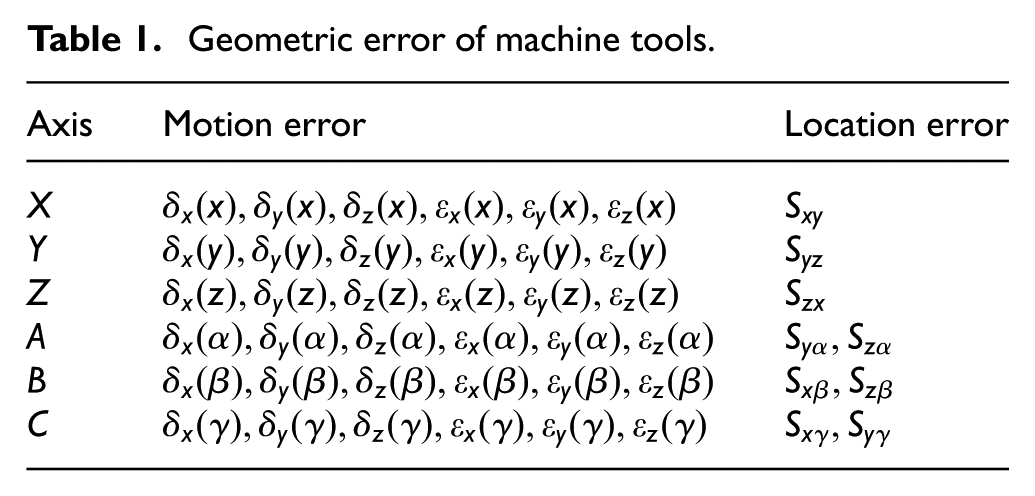
A machine tool has six degrees of freedom at most theoretically. Li and Dai 29 studied geometric error modeling of precision machine tool and presented an error summary of five-axis machine tools. Cheng et al. 30 established the relationship between model of stochastic geometric errors and machining accuracy reliability to identify the key geometric errors. Based on reference to Li and Cheng’s work, we summarize all the possible geometric errors of six axes in Table 1. δm(n) represents translational error in M axis when moving along (about) N axis, where m = x, y, and z and n = x, y, z, α, β, and γ. εm(n) represents rotational error in M axis when moving along (about) N axis. Smn represents the squareness error between M and N axes. The “location error” for X, Y, and Z axes refers to squareness error in Li’s work or perpendicularity error in Cheng’s work. Therefore, Sxy, Syz, and Szx in Table 1 represent squareness or perpendicularity errors Δγxy, Δαyz, and Δβzx, respectively.
Geometric error of machine tools.
The total geometric error is a combination of single geometric errors. It can be expressed by coordinate transformation with a global coordinate frame set on the machine bed, and local coordinate frames located on the corresponding moving components. HTM is a common and useful method which derives representation between two coordinate frames by a single 4 × 4 matrix T

where

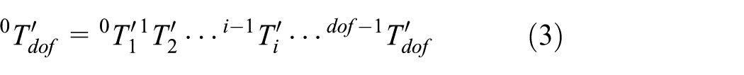
P and R represent the translation and rotation of local coordinate frame in the global coordinate frame, respectively. The position of the end component in a kinematic chain can be calculated by multiplying each matrix that represents the local coordinate frame along the kinematic chain

where i–lTi is the HTM of the ith component with respect to the (i – 1)th component. dof is the degree of freedom of machine tool. Considering the location error and motion error in a kinematic chain, the real position of the end component can be expressed by equation (3)
where

I
4 is a 4 × 4 unit matrix and

Geometric error model integrated wear-out error and clamping error
Apart from geometric error caused by moving components, clamping error of workpiece and wear-out error of cutting tool also have a great influence on machining accuracy. There is no motion error of cutting tool or workpiece because of the relatively static position between cutting tool and spindle box, or between worktable and workpiece. Pitch, yaw, and roll of cutting tool can be expressed in the angular error of spindle box, so that only wear-out error should be considered. Suppose that the local coordinate frames of cutting tool and workpiece both locate at the machining point, the nominal and actual configuration of machine tools are shown in Figure 3.

Nominal and actual configuration of machine tools.
The cutting tool’s coordinate frame and the workpiece’s coordinate frame overlap in nominal configuration. However, in actual situation, there is a diversion between the two coordinate frames because of geometric errors. The total geometric error shown as the dotted vector

where
j is number of components in the kinematic chain of workpiece. f is the equivalent freedom of machine tool and is calculated in terms of f = dof + 2, which means workpiece and cutting tool are added into the new geometric error model. f – j represents the number of components in the kinematic chain of cutting tool.
A conclusion can be drawn in Figure 3 that it is a closed-loop chain from the worktable to cutting tool and workpiece, so that positional relationship among the components can be summarized by equation (5)

where
Pwp and Pt are the location of machining point in global coordinate frame.
Screw mapping of geometric error model
The modeling method using HTM would generate a 4 × 4 matrix with only locational errors calculated in it, which is shown as
Screw expression of HTM
A rigid body can be moved from one position to another by a movement consisting of rotation about a straight line and translation parallel to it. This motion can be called a screw motion. The infinitesimal version of a screw motion is called a twist, and it provides a description of the instantaneous velocity of a rigid body in terms of its linear and angular components. A twist has the form of a 6 × 1 column vector which is a combination of a translational vector and a rotational vector

where v = (v1, v2, v3)T and ω = (ω1, ω2, ω3)T represent the linear velocity and angular velocity, respectively. Geometric errors regarded as small displacements have the same performance with velocity, so that a twist can also represent geometric errors in six dimensions. The mapping between twist and matrix can be concluded as follows 31

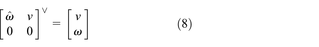
where

s denotes the global coordinate frame. a and b represent two local coordinate frames. Adab shows the path from coordinate frame a to b.
s
Twist superposition of geometric errors
According to the superposition theory of twists, the total error twist of a kinematic chain in global coordinate frame can be expressed through multiplying the adjacent matrix and twists in local coordinate frame. Assume that kinematic chain has R components, with local coordinate frames on them named from 1 to r, the total error twist of r can be calculated by equation (10)

According to equation (10), equation (4) can be translated into a twist form, and the total geometric error twist can be calculated by equation (11)

where
Sensitivity analysis of geometric errors over working space
Based on the proposed model, geometric errors that mainly affect the machining accuracy can be found by sensitivity analysis. Sensitivity analysis is a method to study and analyze sensitive degree of state or output of a model when system parameters or conditions around them are changing. The sensitivity analysis of geometric errors is made by differential the total geometric error
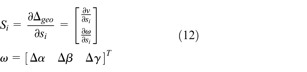
Si, including translational error
SAi is the influence of sith error component on total geometric error. The vital error components should be measured accurately in the compensable directions for numerical control (NC) compensation and minimized in the un-compensable directions during accuracy design stage. The influence of single geometric error on total geometric error is sensitive to the machining position, which is constructed by the relative components of the machine.
In order to construct a complete sensitivity, we need to calculate the whole working space of the machine and then implement the sensitivity analysis method over the full space, instead of analyzing at a fixed position. Furthermore, with clamping errors and tool wear-out errors integrated, realize the variety of sensitivities of the machine. Assuming that it has the same utilization rate over the working space, then the sensitivity coefficient SWi over the working space can be calculated by an integration of the space

V is the working space of machine tool with the range of the stroke of X, Y, and Z. Positional error of machine tool can be calculated by equation (15)


SPi is the normalized sensitivity coefficient of single error that influences the positional error.
Case and discussion
A case validation was performed to evaluate the proposed method. The aim of the validation was to calculate the sensitivity of geometric errors over working space of the machine tool. Take the analysis of a four-axis horizontal boring machine for example, the layout form of the machine tool is shown in Figure 4. The global coordinate frame R is set in the machine bed. Sliding table moves along Z axis with the worktable which rotate about Y axis assembled on its top. The sliding plate attached to the column by ball screw pair moves along X axis and the spindle box moves along Y axis. Due to the difficulties in giving out detailed structures or parameters at the post layout design stage, it is necessary to simplify some parameters and data that cannot be determined at the design stage. The machine tool structure is simplified into the kinematic chain model made up of multiple components. By adjusting the position of components’ coordinate system, the positional relations among components can be calculated according to strokes of the machine tool. All local coordinate frames are located on the corresponding moving component and named by its moving direction. The strokes of moving components along X, Y, and Z axes are 1000, 1100, and 1100, and the position of cutting tool’s coordinate frame is (0,234,323). According to the layout form of the machine tool, the multi-rigid-body model is built as equation (4), and the positional relationship is maintained by equation (5)

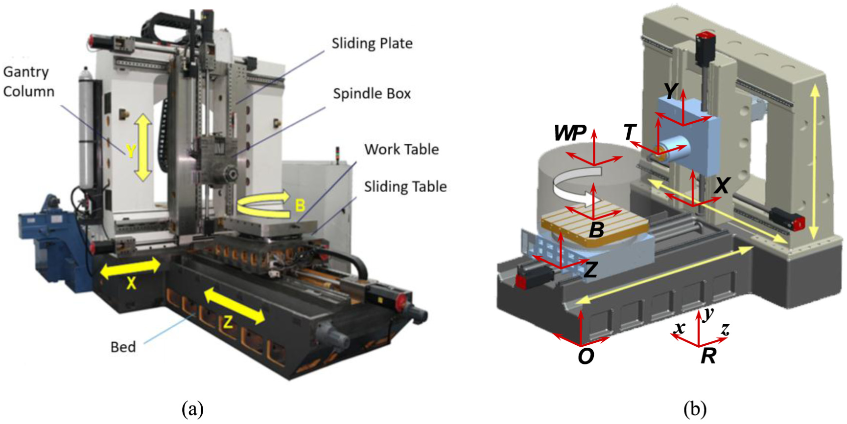
A case study of four-axis horizontal boring machine: (a) structural components and (b) coordinate systems of layout form.
After the layout form was settled, the HTM of every component is determined and shown in Table 2.
HTM of components.

HTM: homogeneous transformation matrix.
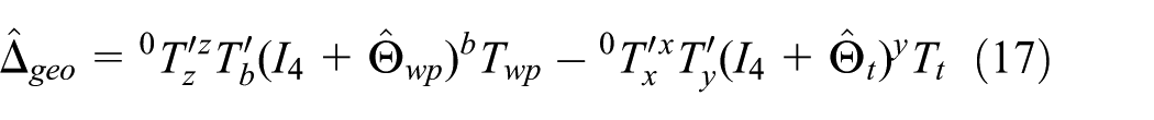
Convert equation (17) into screw form and calculate the adjacent matrix on the basis of Table 3
where

Number of geometric errors.

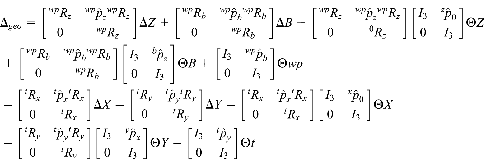
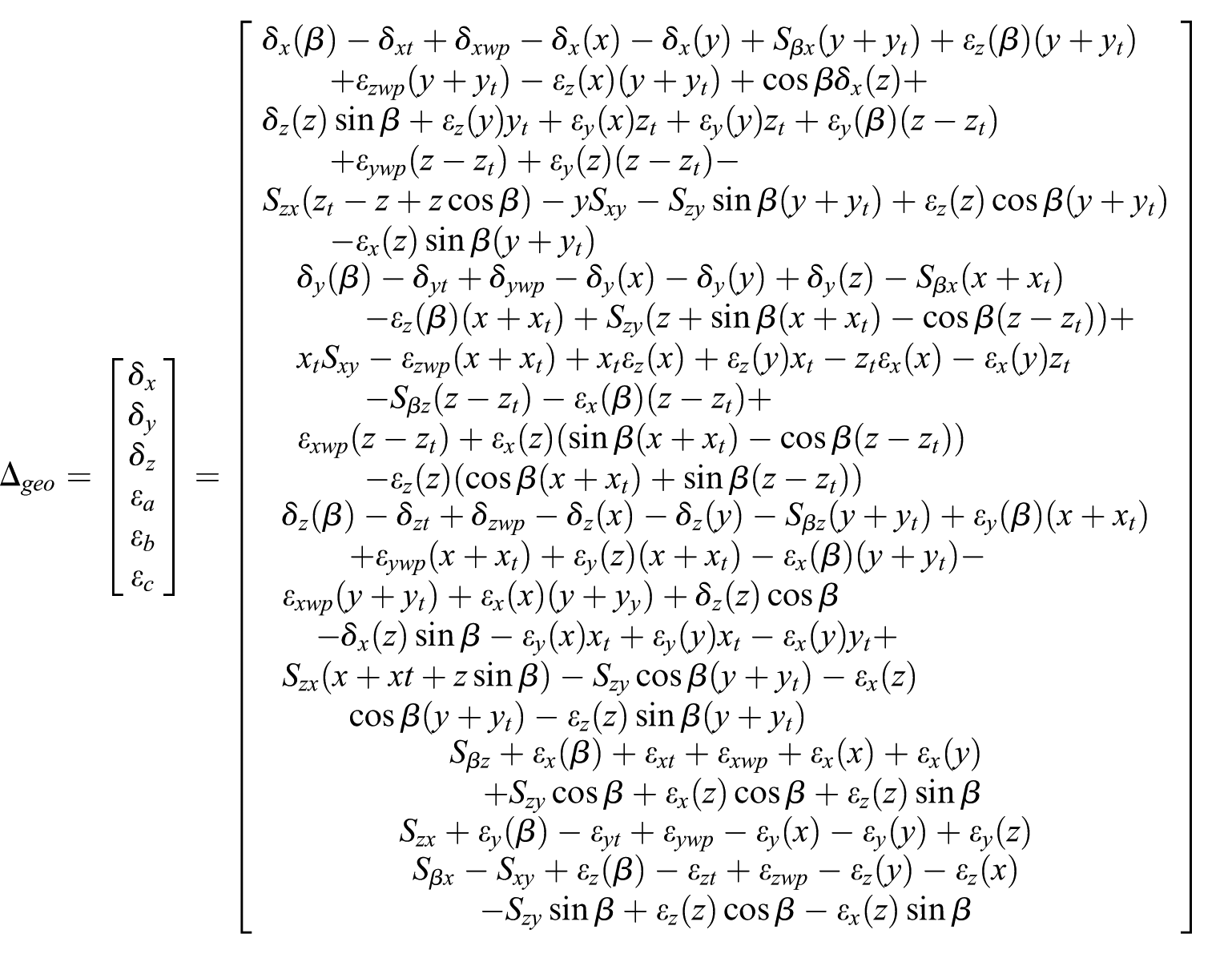
Substitute the geometric errors into equation above and obtain the total geometric error of six dimensions
The influence of every single geometric error on the total geometric error is calculated through equations (12) and (13). Four typical cases of them are shown in Figure 5.

Sensitivity coefficient of geometric errors over the workspace: (a) εx(z) about δx, (b) εx(y) about δy, (c) εx(β) about δz, and (d) εywp about δz.
The influence in direction X of εx(z) is shown in Figure 5(a); the sensitivity coefficient of εx(z) about δx does not vary with the changing of X and has the maximum value of 0.12 and the minimum value of 0.04. The influence in direction Y of εx(y) is shown in Figure 5(b). The sensitivity coefficient of εx(y) about δy does not vary with the changing of Y and decreases with the reduce of Z. Figure 5(c) and (d) shows the influences in direction Z of εx(β) and εywp, respectively.
Based on the sensitivity analysis of single geometric error, sensitivity coefficient in the whole working space of all geometric errors was calculated. For the convenience of expression, all the 38 items of geometric errors are numbered in Table 3.
Results of sensitivity analysis are shown as bar chart in Figure 6. All 38 components’ sensitivity coefficients on four types of errors, which are geometric errors along X, Y, and Z axes (X, Y, and Z axes error) and positional error, are explicitly illustrated. For all these four types of errors, there are three components including εx(z), εz(z), and Syz, have major impacts, which means the value of coefficients on them are greater than 0.1. For Z axis error, it is obvious that there exist more influential coefficients on it, for example, εx(x), εx(y), εx(z), εz(z), εx(β), εxwp, Sxz, Syz, and Sβz, seven of them have the value greater than 0.1, while there are only three components have the value greater than 0.1 for the other three errors. A horizontal machine has its machining spindle and tool placing along the horizontal Z axis, so Z axis is the most important axial direction for its performance, and there exist more components having greater impacts on Z axis.

Sensitivity analysis of geometric errors: (a) X axis error, (b) Y axis error, (c) Z axis error, and (d) positional error.
Conventional views suppose that clamping error of workpiece and wear-out error of cutting tool have little effect on machine accuracy, so there is no extra need to calculate them in the design phase. For tool errors, we can find from Figure 6 that all three items of it have little impact on the machine. However, for clamping errors, εxwp and εzwp have a greater impact, the coefficient value of εxwp is greater than 0.1 on Z axis error, and greater than 0.05 on both Y axis and positional error, while the coefficient value of εzwp is close to 0.1 on X axis error. Hence, the clamping errors of workpiece should be valued in the boring machine.
For the four-axis horizontal boring machine, errors in X, Y, Z, and B axes can be compensated by CNC system while errors in A and C axes should be minimized during the manufacturing and assembly process. From the results of the example, we can see that total geometric error calculated using the proposed method is a combination of that using common multi-rigid-body method,21,22 wear-out error of cutting tool (δxt, δyt, and δzt), clamping error of workpiece (δxwp, δywp, δzwp, εxwp, εywp, and εzwp), and total rotational error (εa, εb, and εc), which could extend the variety of sensitivities over working space and provide a more comprehensive way to analyze and design geometric accuracy.
Conclusion
This article proposes an improved method for geometric error analysis considering the variety of sensitivities over working space. The following conclusions can be drawn:
The HTM of geometric error is transformed into twist by applying the method of screw velocity mapping in the proposed model, to solve the problem that HTM is difficult to describe the rotational error directly, and geometric errors in kinematic chain were expressed by companion matrix of twists.
Compared with those conventional methods of selecting one position, 32 three positions, 23 and interval positions, 19 the improved sensitivity analysis calculates the sensitivity coefficient in the whole working space integrated clamping and wear-out error, which is more reasonable and precise to get the main error sources.
In general, a horizontal machine has better performance than a vertical machine, and the horizontal Z axis with machining spindle and tool placing along it, is the most important axis of all. The sensitivity analysis results indicate that there exist nine influential items with greater coefficients on Z axis error, and we should pay more attention to these items to ensure the accuracy of horizontal machine.
For clamping errors of workpiece, the rotational items of them have a greater impact on X, Y, and Z axes and positional errors. The clamping errors could not be neglected as what conventional views supposed, certain items of them should be considered to be minimized during design, manufacturing, and assembly process, which enhanced the variety of sensitivities. The analysis results would give practical reference and provide some guidance for field assembling of workpiece clamping.
Cutting tool’s wear variety along with time is not taken into account in the article. In the future, cutting tool monitoring devices will be utilized to detect the change of tool wear during the whole cutting process. Therefore, the change rule of tool wear in its lifecycle will be obtained by analysis of collected data, which can be integrated to build a more accurate machine tool precision model.
Based on the analysis results, those components affecting the geometric errors most should be picked out and offer vital evidence for the horizontal boring machine’s geometric accuracy design, which will be discussed in future articles.
Footnotes
Acknowledgements
An earlier version of this paper was presented at the 13th IEEE Conference on Automation Science and Engineering, Xi’an, China, on 20–23 August 2017; the authors thank the organizer and the other participants for their thought-provoking discussion, and the authors are grateful for their helpful comments and suggestions.
Handling Editor: Jan Torgersen
Declaration of conflicting interests
The author(s) declared no potential conflicts of interest with respect to the research, authorship, and/or publication of this article.
Funding
The author(s) disclosed receipt of the following financial support for the research, authorship, and/or publication of this article: This work was partially supported by the Natural Science Foundation of Zhejiang Province (LY18E050001), the National Natural Science Foundation of China (51375437), the Zhejiang Industrial Project of Public Welfare Technology Research (2015C31079), and the Youth Funds of the State Key Laboratory of Fluid Power and Mechatronic Systems of Zhejiang University.