
Abstract
An advanced traction control system can help limit wheel rotation and enhance vehicle stability. This article presents a new traction control system under complicated situations, including the low slippery road surface and split-µ road surface. First, a 15-degree-of-freedom nonlinear vehicle dynamics simulation model is established. Then, the driving wheel speed is regulated by adjusting the engine torque and the wheel brake pressure. The engine torque regulation is based on a proportional–integral–derivative plus ant colony optimization controller, and the wheel brake pressure regulation is based on a proportional–integral plus ant colony optimization controller. Finally, the proposed strategies are applied to simulation and road tests. Results indicate that the algorithm exhibits high control accuracy and robust performance. Compared with the traditional proportional–integral–derivative controller, the proposed strategies improve vehicle acceleration performance and stability.
Keywords
Introduction
Excessive rotation of the driving wheel occurs when the vehicle starts and accelerates particularly on a slippery road, on the hillside, or at turns. In this case, the incorrect reaction of the driver will lead to instability of the vehicle. Traction control system (TCS) can solve these problems and keep the vehicle in the physical range. 1
Many theoretical studies have been conducted on TCS worldwide. According to the adhesion coefficient of pavement, logical threshold control can easily reach the anti-skid control calibration target range; however, a large number of matching tests are needed to obtain the corresponding threshold value, and the development cycle is longer. The structure of a proportional–integral–derivative (PID) control is clear; as such, the calculation speed is fast, allowing real-time control. Therefore, TCS is widely used in the control field. 2 Song and Byun 3 introduced the throttle actuator system of a time-delay PID controller with variable reference model, which exhibits good performance in practical application. Considering the problem on the intrinsic property of PID, Yin et al. 4 proposed a fuzzy controller that effectively prevents driving wheel slipping and reduces the slip rate compared with conventional PID controls. All these methods focus on controlling engine torque. However, a single controller cannot maintain vehicle stability under complicated road conditions. As such, an active brake pressure controller should be combined with an engine torque controller. 5 Kang et al. 6 proposed a coordinated cascade method for controlling engine torque and active brake pressure; the controller is designed using variable structure control theory in sliding-mode. L Li et al. 7 proposed a fuzzy controller to solve the problem of coordination between engine torque and active braking and verified it on uneven low-friction road conditions.
TCS can meet the complex working conditions under active braking and engine-coordinated control. 8 PID controllers have been widely used because of their simple structure, convenient realization and stable and reliable operation. It is very important how to show those PID control systems clearly. 9 The parameters of traditional PID controllers are optimized by manual methods 10 and are unsuitable for all situations. When a vehicle is in a complex environment, it will cause acceleration difficulties and affect vehicle stability.
Optimization problems can make up for this shortcoming, which can be found in many industries and in the scientific community. In contrast to classical mathematical concepts, bionics algorithms (e.g. ant colony, genetic, and particle swarm algorithms) have been developed through simulation of natural ecological systems to solve complex optimization problems. These algorithms greatly enrich the current optimization techniques and provide practical solutions for combinatorial optimization problems that are difficult to deal using traditional optimization techniques. Ant colony optimization (ACO) is suitable for solving complex computing problems especially in optimizing PID parameters based on insect behavior under different environments.11,12 Ant algorithm has attracted increasing research attention since it was established and has been successfully applied in traveling salesman problem (TSP),13,14 vehicle routing problem,15,16 and mobile ad hoc networks.17,18 Several parameter optimization methods have been proposed for ACO.19–22 Duan et al. 19 introduced an ACO algorithmic approach for optimizing the parameters of a nonlinear PID controller and proved that it has good control and robust performance. Furthermore, ACO has been applied in dynamic systems. The system based on the adaptive ant colony (AAC) design also successfully optimizes the dynamic model from preprocessing flight data.23,24 In this study, ACO is used to design TCS. Given that ACO can be easily combined with other local algorithms, it can make up for the dynamic response that PID cannot obtain and thus improve the stability and acceleration of the vehicle.
This article proposed a combined solution to the vehicle traction control problem. The wheel speed regulation realized with engine torque control and active braking control. A PID control system has been designed for engine torque regulation and a proportional–integral (PI) controller has been employed for wheel brake pressure regulation. For both control system, the controller gains have been tuned by using a metaheuristic optimization method named ACO. The significance of this article is to improve a TCS using ACO. The proposed control approach was tested with low μ slippery road surface and split-μ road surface simulations in the simulation and real vehicle test, which proves the effectiveness of the method. Compared with the traditional TCS algorithm, the ACO-optimized TCS improves the acceleration performance and reduces the number of adjustments.
The rest of this article is structured as follows. The vehicle dynamic model is provided in section “Vehicle model.” The practical problem of the conventional algorithm is discussed in section “Conventional TCS.” Section “Controller design” describes the controller design, which includes an engine controller and an active brake controller. In section “Improved ACO algorithm” the parameter optimization strategy for the PID controller using the ACO algorithm is described. In section “Result and discussion,” the results of simulation and real-car validation are shown in detail. Discussion and further research topics are also presented. Finally, section “Conclusion” summarizes the article.
Vehicle model
Body model
A nonlinear 15-degree-of-freedom (DOF) vehicle model is used to predict vehicle response under different road conditions during various driving maneuvers, as shown in Figure 1.
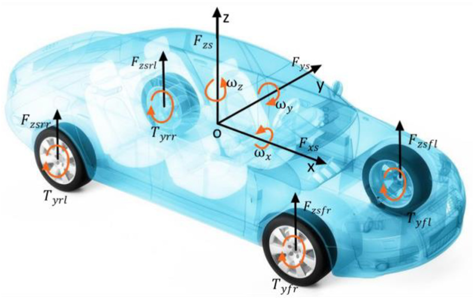
15-DOF vehicle model.
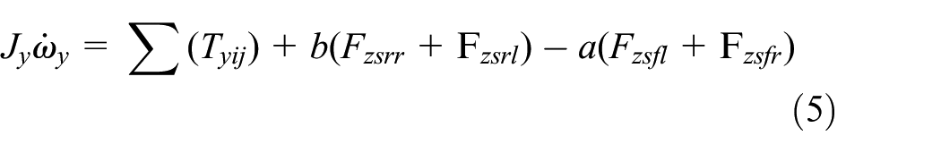
TCS controls the vehicle’s longitude dynamics but ignores several factors. In this article, the vehicle model includes longitude motion, lateral motion, vertical motion, roll motion, pitching motion, and yaw motion. The vehicle dynamic equations can be described as follows


Wheel rotational equations can be expressed as

Tire model
The tire model selected is the magic formula model proposed by Professor Pacejka. 25 This model is a mathematical expression based on the tire physical prototype, which is used to accurately calculate the tire forces in the longitudinal and lateral directions. 6 The equation of the tire longitudinal forces y can be defined as

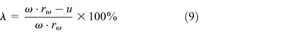
The slip ratio of tire can be expressed as follows
Engine model
An engine is a complicated system. Many factors affect the engine torque output, but the most important are the throttle opening

The engine output torque depends on throttle angle and rotation speed.
Conventional TCS
During the driver’s full-throttle acceleration, the driving wheel torque exceeds the maximum tire adhesion force between the tire and the pavement. The traditional TCS algorithm is often faced with two problems. On the one hand, the brake control responds quickly, but the torque of the engine cannot be reduced immediately because of the relatively low dynamic response of the engine. On the other hand, controlling the torque and braking torque simultaneously is difficult. Therefore, the reduction of engine torque and the generation of wheel brake torque require optimization using high-precision control algorithms to reduce the rotation of the wheel.
ACO exhibits a great advantage in solving optimization problems. On the one hand, the ant algorithm is a positive feedback and used as a search and optimization tool in engineering because of its effectiveness in finding very good solutions to difficult problems. On the other hand, ACO is a heuristic algorithm of population and has strong robustness and optimization ability. The ant colony algorithm is a bionics algorithm based on ant colony and has the advantages of good robustness.
This work applies ACO to optimize the conventional PID controller, which has the advantages of simple structure, good robustness and, high reliability.
Controller design
Control scheme
The overall structure of the TCS is shown in Figure 2. Given the lack of transverse differential lock controller’s braking application, the driving force can be transmitted on both sides when the driving torque on both sides of the differential is equal. 1 The larger driving torque causes the slipping of the low-side wheel, resulting in velocity difference higher than 0. In this case, most of the drive torque will be lost in the differential speed, the engine, and the transmission. The wheel speed difference in the driving wheel is 0, which is considered as the desired value of TCS. The system monitors each wheel and adjusts the brake pressure and engine torque, thereby optimizing the stability and acceleration characteristics of the vehicle.

The structure of TCS.
In general, vehicle acceleration presents difficulties under typical road conditions, namely, low μ pavement and the split-μ pavement. Vehicle longitudinal velocity is important for electronic stability control system; in the meantime, vehicle longitudinal velocity is estimated based on wheel speed signals. When the vehicle enters the acceleration fault, the accuracy of speed estimation will be directly affected, which leads to a larger error in slip calculation. This article proposes a control scheme to solve the problem by maintaining the traction wheel speed.
The driving wheel may slip under the slippery surface condition. The engine torque regulation is based on a PID plus ACO controller to adjusting driving wheel speed, and the active brake regulation is based on a PI plus ACO controller to adjusting the wheel brake pressure. Static friction coefficients differ under split-μ road condition. The engine torque controller and active braking controllers work together to avoid excess spinning of the wheel. First, the active brake controller based on the wheel speed signal is judged on one side of the driving wheel skid, providing proper strength of the wheel through active braking. The adjustment on the other side of the driving wheel improves the rate of adhesion and enhances the ability to pass through the wheel. In the second step, the engine output torque is chosen to reduce the output torque.
Engine output torque controller
The output of the torque controller of the engine is the optimal driving torque, which reduces the throttle opening of the engine to limit the torque of the driving wheel, so the driving wheel will not over slide.
The target wheel speed of the driving wheel can be calculated according to the optimum slip ratio, which can be expressed as

Target of the slip design.
When the wheel speed of the driving wheel is greater than that of the non-driving wheel, the speed difference between the wheels on both sides of the driving wheel is very small, which indicates that the driving wheel is skidding. At this moment, the engine torque control takes the leading role, in which the average value of the wheel speed of the two-driving wheel is expressed as

Active brake controller
The active brake pressurization rate is high, and the lag time is short. The wheel responds very quickly to pressure interference, which easily causes large fluctuation in wheel speed.
When the traction controller detects that one or more driving wheels rotate faster than the other wheels, it calls active brake controller to apply brake friction to restrain wheel skid and reduce traction force. Braking on the skid-wheel will transfer driving torque to the other side of the wheel through the differential mechanical behavior.
Given that the wheel speed signal of the actual vehicle controller contains noise, derivative element easily causes repeated fluctuation of the control quantity and is not conducive to the stability of the braking regulation; thus, PI control mode is presented as follow

Improved ACO algorithm
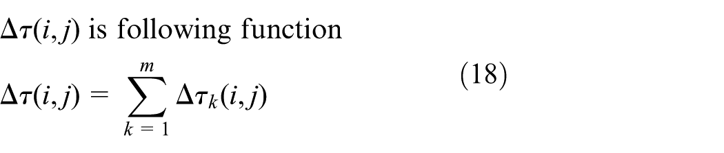
A group of control parameters cannot adapt all environment conditions. The ant algorithm is a positive feedback and is used as a search and optimization tool. Hence, a method for ACO identification is proposed to obtain optimally designing parameters of TCS. The PID parameters are optimized in this study by using the parameter optimization strategy proposed by Duan et al. 19 Let the objective function be

which is also named a cost function.
In solving PID problems, let

Assuming M is the number of ants, and M ants are randomly distributed on these nodes. In a discrete space, ant movement is the transition from one state to another. Pheromones will be stored on the route. The strength of the pheromone accumulation of edge
Equations (15) and (16) indicate the state transition rules, which are used to represent a real ant K located at node i and select the next node j. Equation (15) is a greedy choice of technology and is the optimal combination of short distance and large pheromone level; equation (16) balances this problem by allowing the probability of the next node to be selected


The larger the
All ants perform the pheromone global update after each construction step. In addition, we use an elitist strategy to accelerate the search speed. At the end of each cycle, additional pheromone enhancements are added to all of the already found optimal solutions to make the optimal solution found to be attractive to ants in the next cycle. We can obtain the following formula

in which

This process continues until a certain number of iterations or solutions have been implemented. Based on the above concepts, the process of solving nonlinear PID with improved algorithm is shown in Figure 4.
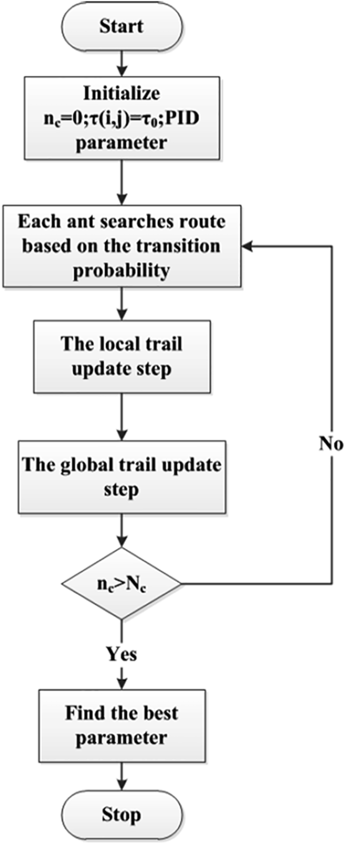
The flowchart of ACO.
The two controller optimization methods are the same; therefore, the parameter optimization of PI control will not be discussed here.
Result and discussion
Simulation result
MATLAB/Simulink is used, and simulations are carried out under some typical conditions to validate the performance of the proposed algorithm. The vehicle model parameters are shown in Table 1. In the simulation, the acceleration pedal is 100% without steering angle input. The characteristics of the vehicles with the TCS, without TCS and traditional TCS are analyzed and compared. The following indices are used: FL represents the front-left wheel, FR represents the front-right wheel, RL represents the rear-left wheel, and RR represents the rear-right wheel.
Values of the vehicle parameters.
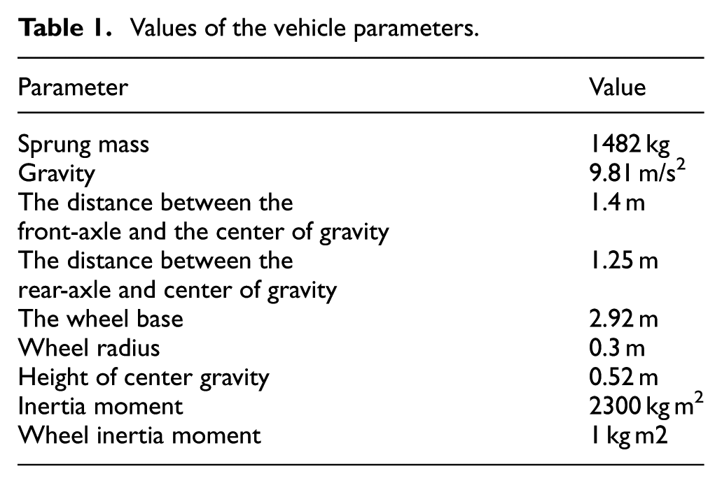
Table 1 lists the other parameters of the vehicle model for simulation.
Low μ slippery road surface
As shown in Figure 5(a), the friction coefficient of the road surface is 0.2; when the controllers do not operate, the four wheels are severely skidding on the slippery road. When the driving force on the wheel is faster than the maximum adhesion force provided by the road, the wheel turns to slip and cause traction loss. As shown in Figure 5(b), the use of traditional PID control method makes up for the difficulty of vehicle acceleration on low attached pavement. Although this method exhibits better acceleration performance and restricts the wheel skidding to a certain extent, the speed of the four wheels is greater than the vehicle speed; hence, the wheels are always sliding, and the driving force is consumed at the differential speed. As shown in Figure 5(c), at 0.445 s, the TCS based on ACO optimization starts to control the transition of the wheels. Under the joint adjustment of the engine output torque controller and the active brake controller, the wheels are effectively restrained and the vehicle speed increases gradually. The proposed algorithm is better than that without TCS and traditional TCS. From Figure 5(b) and (c), the comparison between the traditional control and the optimal control shows that the speed of the vehicle with traditional control is 19 m/s at 7 s, whereas the speed of the optimal control is 19 m/s at 6 s. Therefore, the acceleration is better than in the vehicle without TCS intervention. Compared with the traditional PID algorithm, the proposed TCS controller exhibits the same acceleration effect, but the method can reduce the adjustment times by about 55% under slippery road conditions and further improve the dynamic and steady-state performance of the system.

Velocity versus time in the low μ slippery road surface: (a) velocity versus time with no control, (b) velocity versus time under traditional control, and (c) velocity versus time under control.
The motor torque adjustment is shown in Figure 6(a). Before 0.445 s, the actual output torque of the engine increased rapidly to 135 Nm according to the driver’s intention. At 0.445 s, the excessive rotation of the wheel is detected by the controller. From 0.445 to 1 s, the torque is rapidly reduced to 60 Nm, and the acceleration performance of the vehicle is improved gradually. At 5.95 s, the actual engine torque is greater than the driver’s torque, the engine output torque controller exits, and the vehicle accelerates according to the driver’s intention. The optimization parameters of torque regulation are obtained by simulation

Simulation results in the low μ slippery road surface: (a) torque versus time under control and (b) cylinder pressure versus time under control.
The active braking adjustment is shown in Figure 6(b). The main object of the braking adjustment is the relatively fast speed of the driving wheel. As shown in Figure 5(c), the left rear wheel is faster than the right rear wheel at about 1 s; at this moment, the braking of the left rear wheel is close to 3.5 bars. From 1.5 to 6 s, the right front and left front wheels alternately brake. At 6.5 s, as the speed difference of the driving wheel tends to 0, the active brake controller exits. The optimization parameters of braking adjustment are obtained by simulation:
Split-µ road surface
As shown in Figure 7(a), the vehicle without TCS is difficult to drive on the split-µ road surface, where the left side is rough road (μ = 0.8) and the right side is slippery road (μ = 0.2). The right wheel is on the low side and will greatly slide without the TCS controller. As shown in Figure 7(b), the use of traditional TCS improves the acceleration performance of the vehicle compared with the system without TCS. However, the low-side wheels are still skidding, resulting in waste of energy from 3 to 8.5 s. This long-time adjustment may cause damage to the controller in real vehicle test and cannot meet the control accuracy requirements. The simulation results show that the coefficients of adhesion are 0.8 for the left road and 0.2 for the right road in Figure 7(c). At 0.445 s, the TCS based on ACO optimization inhibits the transitional slip of low-side wheels. The engine torque no longer increases as the accelerator pedal opening increases. Under the action of active braking, the TCS can effectively restrain the slip of the slippery side wheel and improve the speed by utilizing rough side wheel. From Figure 7(b) and (c), the comparison between the traditional control and the optimal control shows that the speed of the vehicle with traditional is 19 m/s at 8 s, whereas the speed of the optimal control is 19 m/s at 5.3 s. Therefore, the proposed method is better than the previous two methods on the split-µ road surface. The acceleration in the method with TCS is 80% higher than that without TCS and 50% higher than that in the traditional PID control method.

Velocity versus time in the split-µ road surface: (a) velocity versus time with no control, (b) velocity versus time under traditional control, and (c) velocity versus time under control.
The engine torque adjustment is shown in Figure 8(a). At the beginning, the engine output torque increases with increasing throttle opening. During skidding of the side wheels, the engine output torque does not adjust to the low torque, as in low-profile pavements, but is maintained at 120 N m, thereby ensuring the acceleration of the vehicle. The optimization parameters of torque regulation are obtained by simulation:

Simulation results in the split-µ road surface: (a) torque versus time under control and (b) cylinder pressure versus time under control.
The active braking adjustment is shown in Figure 8(b). To improve the acceleration of the vehicle on the road surface, active pressure interference is only carried out for low-side driving wheels. In this process, the low-side drive wheel is subjected to the active interference pressure, and the maximum interference pressure reaches 12 bars. The optimization parameters of braking adjustment are obtained by simulation:
Road test result
An experimental study was carried out in the test field of Heihe City of North China to verify the performance of TCS on winter road condition. The simulation and experimental results were applied to the experimental vehicle (front-engine, front-wheel-drive layout), as shown in Figure 9. The vehicle was refitted to facilitate vehicle testing and incorporated with four pressure sensors and TCS controller. The controller installed in the engine room was integrated on the hydraulic unit (HCU). Relevant data were recorded using Vector CANalyzer from CAN bus.

The real test vehicles on the packed snow ground.
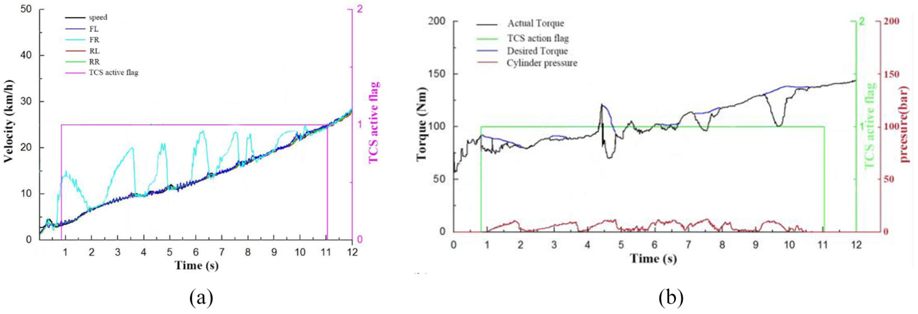
Under the coordination of active braking pressure and engine torque regulation, the wheel speed is obviously smooth on the low-friction road (μ = 0.2) and the split friction road. The high adhesion of the separated pavement is the concrete surface, which has a friction factor of about 0.8. The low-adhesion side is an ice surface with a friction factor of about 0.2.
As shown in Figure 10, before 1.5 s, the engine has a large output torque, which makes the drive wheel slide. The target torque may be large in the short time after the intervention. With the sliding of the wheel, the controller can quickly reduce the engine output torque and maintain a certain driving force. The pressure curve is not drawn because the braking pressure is 0 during control process. The torque oscillation of the front wheel has obvious smooth characteristics. The optimized parameters obtained are

Velocity versus time in the low μ slippery road surface: (a) wheel speed and vehicle velocity and (b) the winter test results obtained on the snow road.
As shown in Figure 11, the vehicle starts from the stationary state on the separation road. After the slipping of the low-side wheel, TCS is activated, and engine management system and hydraulic brake modulator are controlled. The controller can exert braking force on the wheel in time so that wheel speed can be restored. The brake pressure was intervened several times with the transition of the wheel, and the maximum value is 15 bars. TCS improves the driving force of the low-side wheel and effectively prevents the wheel from overturning from 1 to 10 s, as shown in Figure 11(b). The engine control exits frequently, which can affect ride comfort. The optimization parameters of torque regulation are obtained by simulation:
The winter test results obtained on split-µ road surface: (a) wheel speed and vehicle velocity and (b) torque.
Discussion
In contrast to other automotive engineering strategies, the new bionic strategy exhibits good adaptability to terrain. This strategy can not only meet the general operational requirements but also improve the dynamic performance through TCS under severe conditions.
The control objectives of TCS are mainly divided into slip rate and speed types. The phenomenon of vehicle speed is corrected based on slip rate control.4–6,26–29 In this study, we design the control target of TCS based on speed control. As shown in equation (9), slip rate is calculated based on wheel and vehicle speeds. When the driving wheel is over sliding, the slip rate cannot be calculated. Therefore, slip rate should not be calculated based on TCS control. The choice of target wheel speed can not only be used to observe wheel speed but also to reflect slip rate. Based on this perspective, the advantage of this work compared with previous research is that the acceleration performance of vehicles is better, and the traction loss is smaller on low and separate roads. For example, in the real vehicle test of ice and snow road, the driving wheel only skips once, which effectively reduces the transition consumption of driving force.
The proposed strategy also uses ACO to optimize the PI parameters of the torque controller in TCS. 30 Given that the pressure controller is not considered, the single engine torque controller is difficult to meet the requirements of TCS split-µ road surface. Therefore, in the simulation test of the split-µ road surface, the vehicle speed was approximately 5.81 m/s at 5 s with ant colony PI controller, while it was approximately 19 m/s at 5.3 s with the ACO-optimized TCS controller.
In the study of the slip ratio as control target, the PID controller combined with the optimal longitudinal slip rate identification, 31 and the vehicle speed was approximately 14 m/s at 4.5 s under low-adhesion road, while it was approximately 19 m/s at 6 s with the ACO-optimized TCS controller. The proposed method is faster than the other methods. Hence, the control strategy is excellent, and the optimization results are significant. The ant algorithm is also applicable and reasonable for study of vehicle stability.
Conclusion
This article introduces a new TCS based on ACO for engine torque and pressure controllers. The integrated strategy is more complex than the traditional PID control. The ACO is used to optimize the PID/PI parameter strategy for TCS. The strategy is tested on uniform adhesion and split-μ based on MATLAB/Simulink. The results show that TCS prevents excessive slip and improves the acceleration performance of vehicles. The method is also verified by real vehicle tests. The acceleration performance of the vehicle is significantly improved. In contrast to the conventional TCS algorithm, the TCS based on ACO optimization improves the acceleration performance and prevents excessive slip under complicated road surface conditions. Compared with the traditional method, the proposed method can also reduce the number of adjustments by about 55% under slippery road conditions and increase the acceleration speed by 50% on the split-µ road surface.
Therefore, the proposed method may provide new opportunities for novel TCS algorithms. The proposed contributions here were verified through simulations and real vehicle tests. This work offers reference value for further research of TCS.
The current research on ACO has been conducted considering that the original single TSP has penetrated into various applications. One-dimensional (1D) static optimization problem is solved to address multidimensional dynamic combinatorial optimization problems. The discrete domain range gradually extends to research with continuous scope. Thus, the new bionic optimization algorithms show great vitality and broad prospects for development.
In future works, we will focus on the following aspects:
More complex working conditions, such as slope on the road, will be tested to verify the proposed method. 8
ACO will be applied to other automobile stability control systems and compared with other mainstream methods to improve the control effect.
The proposed algorithm will be applied to other types of cars, such as pure electric vehicles and vehicles equipped with in-wheel motors.
Footnotes
Appendix 1
Handling Editor: Yangmin Li
Declaration of conflicting interests
The author(s) declared no potential conflicts of interest with respect to the research, authorship, and/or publication of this article.
Funding
The author(s) received no financial support for the research, authorship, and/or publication of this article.