
Abstract
When coiled tubing is applied in high oil–gas wells, buckling load of a coiled tubing under the injector is the key for functionality. The coiled tubing is curved, but it is simplified to straight tubing for buckling load solved in the past. These calculations were not sufficient for the problem. In this article, buckling load of a bent coiled tubing is discussed based on the actual details of the exploitation. First, the coiled tubing curvature changes during the working period reaching the shape presented in analysis of the article. To determine the distribution of stress and the zones to failure, a coiled tubing was studied using the theory of curved beam moment, and buckling load of the bending coiled tubing was derived. The study has indicated that the gooseneck curve radius and the yield strength enable to determine the residual curvature of coiled tubing. The axial stress along the convex and concave sides is a half periodic sine and cosine distribution along the length of the coiled tubing, and the maximum axial stress is on the middle of the concave side of the outside diameter of the coiled tubing. There is an inversely proportional relationship between buckling load and length of the tubing, and a proportion of buckling load and the diameter–thickness ratio. Moreover, buckling load was more sensitive to the tubing length than its wall-thickness.
Introduction
Coiled tubing (CT) is also called flexible pipe; it is twined around the roller. When it is deployed, the CT is pulled out of the roller and pushed into the well by the injector. CT equipment is used in various processes including workover, drilling, and logging. With development of technical level of equipment manufacturing technology, the number of CTs used in high-pressure wells increases. When CT is employed at high-pressure wells, the tubing is snubbed in the wells by the injector against the wellhead pressure. The tubing between the injector and stripper is bent and unsupported (Figure 1). If the compressive load on the CT increases too much, it causes catastrophically buckle in this unsupported interval. 1

CT between the injector and stripper: (a) CT pushed out from an injector, and (b) CT enters a stripper.
Y Yang 2 studied the failure of straight tubing under the outer diameter pressure and found a relationship between the collapsed compressive stress and the tensile force. K Newman et al. 3 used the equation from Gordon–Rankine and obtained the buckling load of the CT, but he assumed that the CT is straight. AS Zheng and A Sarmad 4 experimentally studied the tubing deformation under internal pressure and axial compressive load. S Houliara and SA Karamanos 5 used finite element analysis to follow the structural stability of long-uniform pressure-thin tubing under bending. JA Paquette and S Kyriakides 6 experimentally examined plastic buckling and instability for long tubing under internal pressure and axial compressive pressure. MB Elgindi et al. 7 used numerical analysis to investigate thin long linear material tubing. G Shi et al. 8 discussed buckling deformation and capacity of welded pipeline. X Qin and D Gao 9 set up an analytic equation for the residual bending CT buckling load in CT applied in a horizontal wells.
The objects tested by the authors mentioned in this article are long-straight tubes. However, the CT between the injector and the stripper has residual curvature. The stress distribution for straight and bending pipes is very different. Therefore, it is not accurate to simplify the bending pipe to straight pipe. Therefore, the tubing curvature changes are studied, and the residual pipe curvature is obtained. Using a numerical method to simulate the bent tubing, the distribution of compressive stress along the pipe and the reasons for failure are determined. Following the emulation results and using the theory of a bent beam, a new buckling load equation for CT residual bending is derived.
Residual curvature of the CT
The CT is hauled from the roller, through the gooseneck and enters the injector (Figure 2). It is bent by the gooseneck, and the chains inside the injector straighten the tubing when it passes through the injector. After the CT is pushed from the injector, it rebounds due to the material elastic energy. Thus, the CT has residual bending deformation.

A scheme of the CT equipment.
The CT residual curvature is decided by the gooseneck and the rebounding curvature. The rebounding curvature is affected by CT material and bending moment.
Material
The requirements for the tubing include the ability to withstand high stress, good forming, and low sensitivity. CT grade is CT80, manufactured by Baoji Petroleum Steel Pipe Factory of China, for example. Its uniaxial extensional deformation 10 is shown in Figure 3.
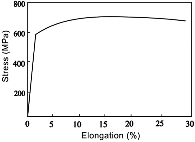
Stress–strain curve of the CT80.
As shown in Figure 3, the performance of material hardening is not obvious in CT80 steel. The steel constitutive relation is simplified in this article; the tubing is assumed to be isotropic material having ideal elastic–plastic stress–strain relationship. The material behavior under tensile force is represented as follows

where E is Young’s modulus, MPa; ε is strain; εe is the elastic strain; and
When elastic–plastic deformation occurred on the tubing cross section, loading and unloading behavior follows the theory of Hooke’s law in the elastic area. In the case of plastic zone, the loading behavior is related to ideal elastic–plastic rule and unloading behavior is subjected to simple unloading formula (as shown in Figure 4)


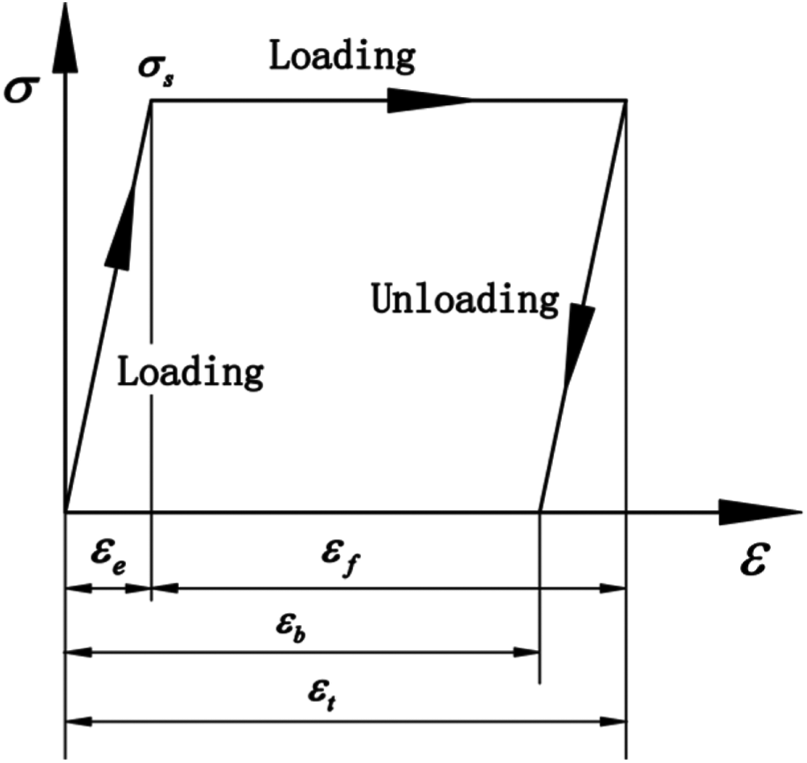
A scheme of loading–unloading curve.
where
CT residual curvature
As we can see from Figure 5, the relationship between strain and curvature of a CT during the bending process presented as follows 11


Relationship between curvature and strain.
where D is the outer-side diameter of the CT, m; Rt is the radius of curvature, m; and Ct is the curvature, rad.
Figure 6(a) expresses the relationship between a strain and a curvature


Strain and tangle angle on the specimen: (a) relationship between Ct and
As shown in Figure 6(b), the length of the edge corresponding to the tangent of the curvature value can be expressed by employing strain produced by the curvature.
When a CT in the state of working, the shape of the CT is formed by bending, straightening, and bending to straightening. The curvature of CT is changed four times. In which, the last two curvature changes have a significant influence on the residual curvature.
The CT is assumed to ideal elastic–plastic material (as shown in Figure 4); when the material is loaded, then elastic–plastic strain is appeared; when material is unloaded, it will rebound under the action of elastic energy of itself, and the rebound strain equals the critical elastic strain
As shown in Figure 7, the CT is assumed to straight pipe before entering to the gooseneck. The gooseneck curvature radius is less than critical elastic curvature radius of CT; when it passes through the gooseneck, the CT is subjected to plastic and elastic strains, and the cross section 1-1 is rotated to section 2-2, the strain

Laws of changes of strain.
When a CT is pulled out of the gooseneck bracket, it rebounds under the action of its elastic potential energy. The direction of the rebound is opposite to the direction of loading. A rebound strain

because the clamping device of an injector is between two parallel plates. When a CT is entering to an injector, the CT is bent to straight again, and the cross section 3-3 is rotated to section 1-1, and the strain
If
The strain of out diameter of CT at the position of gooseneck bracket is

where R represents the radius of gooseneck bracket, m. The critical elastic strain of material is

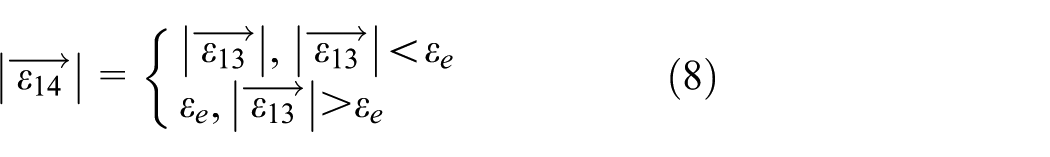
Combing equations (7), (9), and (10), the strain of

Substituting equations (9)–(11) to equation (8), the final residual strain of CT can be obtained

The final curvature radius of CT is named R0, according to equations (4)–(6)


Combing equations (11) and (14)

As we can see from equation (15), the residual curvature radius is affected by the radius of gooseneck, the diameter of CT, yield strength, and Young’s modulus of material. As shown in Figure 8, when the value of R is less than point A, a CT produces the same R0. this phenomenon indicates that the residual curvature strain of the CT before it enters the injector is great than critical elastic strain of material. The R0 is proportional to the outer diameter of CT. When the outer diameter of CT is 30, 40, 50, and 60 mm, the R0 is 8, 9, 10, and 11 m. When the value of R is bigger than point A, R0 is increasing, and the rate of increasing is inversely proportional to the outer diameter of CT. This phenomenon indicates that the residual curvature strain of the CT before it enters the injector is less than critical elastic strain of material.

Relationship between residual curvature radius and radius of gooseneck bracket (σs = 500 MPa, E = 206 GPa).
As shown in Figure 9, when the value of R is less than the point B, the R0 is inversely proportional to the yield strength of CT; the yield strength is 400, 500, and 600 MPa; and the R0 is 12.8, 10.3, and 8.6 m. When the value of R is bigger than point A, R0 is increasing, and the rate of increasing is proportional to the yield strength of CT.
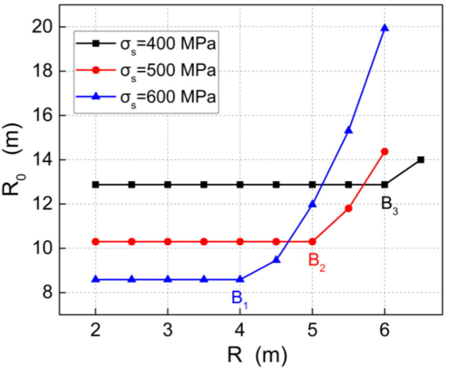
Residual curvature radius of 2 in CT with the different yield strengths.
Forming equation of the residual curve tubing
Mechanical characteristics of bending CTs under the axial compress are different from the straight ones. The moment produced by the axial compressive force and deflection was found on the bending tubing cross section. The moment produced axial compressive and tensile stresses on the cross section. However, there is only axial compression stress on the cross section of the straight tubing. This is the main difference between the bent tubing and the straight tubing. The shape equation and deflection of the bent CT are solved.
Mechanical model of forming equation
As shown in Figure 10, the central line between the injector and stripper is the
Mechanical model of bent CT under an axial force.
Assuming that the center coordinates of circle C is at the point

where L is the distance between the injector and stripper.
Considering the tubing form, the center coordinates of the circle C should be at the concave side of the tubing, equation (16) can be shown as follows

The form of the tubing between the injector and the stripper is formulated in the following manner

Deflection of the bent tubing
When

The 1-inch CT was analyzed as an example. In the same distance L = 1 m, the relations between the deflections and the residual curve radii were obtained, as shown in Figure 11.

Deflection curves.
The value of deflection
In the same residual curve radius R0 = 8 m, the deflection changes with different distances are expressed as shown in Figure 12.

Deflection curves at different distances.
The deflection of the tubing increases as distance increases.
Buckling load for the tubing with residual curve radius
Taking into account preamble analysis, the position of the neutral plane on the cross section affects the distribution of the compressive stress. The position of the neutral plane is decided by the curve radius of the tubing.
Curve radius of the neutral plane
The relationship between the radius of the neutral plane, the centroid, and the curve radius of the tubing is shown in Figure 13.

Radius on the cross section.
The radius of the neutral plane can be express as

where


where

Causing

Combining equations (26) and (25), equation (24) can be expressed as

Stress on the cross section of CT
According to the theory of the moment of the bent beam, the bending stress at the x position of the suspended section and at z position of the cross section can be followed as

where
A CT will bend to the convex side under an axial force. The distance between the position of outer diameter and the neutral layer of the section is the maximum, and the value of the distance is calculated by equation (28). There are tensile stresses and compressive stresses on the cross section of CT. When a tube is bent, with the neutral layer as the boundary, the bending stress at the outside of the convex side of the CT is tensile stress

The bending stress at the outside of the concave side of the CT is compressive stress

Under the action of axial force, the bending stress produced by the bending moment and the axial stress produced by the axial force are on the cross section of the bent CT. At optional position, the axial force perpendicular to the cross section of the curved CT is

Considering the direction of stress, the stress on the cross section at the outer diameter of the convex side of the CT is

The stress on the cross section at the outer diameter of the concave side of the CT is

Buckling load
Comparing equations (32) and (33),

Naming the buckling load as


Calculation results
Distribution of stress on cross section
In order to directly reflect the relationship between the axial stress and the residual curvature radius, a CT is studied. The CT is 50 mm, the outer diameter is 25.4 mm, the wall-thickness is 2.2 mm, the curvature radius of CT is 6 m, and the axial force is equal to 10 kN.
As shown in Figure 14, the axial stress at the outer diameter of the concave side is greater than the axial stress at the outer diameter of the convex side. In the axial force, the concave side of the bent tube is more prone to failure than the convex side. The axial stress along the tube is approximately sinusoidal half cycle, and the maximum stress is at 1/2 of the CT length. The axial stress at the outer diameter of the convex side and the concave side is approximately symmetrical. The diameter of the CT is inversely proportional to the axial stress at the outer diameter of the concave and convex sides.

Distribution of axial stress along the convex and concave sides.
As shown in Figure 15, under the same length, when the residual curvature of the continuous tube is 2, 4, and 6 m, the maximum axial stress is 120 MPa, 80 MPa, and 60 MPa. The axial stress is inversely proportional to the residual curvature radius.

Relationship between axial stress and residual curvature radius.
Relationship between the buckling load and curve radius
When the distance between the injector and the stripper was

The buckling load and the residual curvature radius.
In the same conditions, the result in this article is greater than the Gordon–Rankine
Relationship between the buckling load anddistance L
When the curve radius is

The buckling load as a function of distance L.
In the range of 1 m, the results calculated by Euler’s exceed the material yield load. Thus, Euler’s equation is not appropriate. When the CT length is relatively short, the buckling load should equal to the yield load, but the value calculated by Gordon–Rankine is less than the load at 50 kN for a yield point. The value calculated in article is equal to the yield load. Thus, the method used in this article is more accuracy than the Gordon–Rankine conception.
Relationship between the buckling load andwall-thickness ratio
When the distance between the injector and the stripper is 30 mm, the residual curve radius of the tubing is 3.5 m, and the relation between the buckling load and the wall-thickness ratio is shown in Figure 18.

Relationship between the buckling load and the wall-thickness ratio.
The buckling load is proportional to the wall-thickness ratio. When the wall-thickness is 2.5 mm, with the wall-thickness ratio increasing to one unity, the buckling load improves to14.5 kN. When the wall-thickness is 4 mm, with the wall-thickness ratio increasing to one unity, the buckling load reaches 38.4 kN.
Conclusion
The gooseneck curvature and the yield strength of CT are the main factors that determine the tubing residual curvature.
The axial stress at the outer diameter of the concave side of CT is greater than the stress at the outer diameter of the convex side. The axial stress along the CT is approximately sinusoidal half cycle; in the axial force, the concave side is more prone to failure than the convex side.
The forming equation and the deflection equation are developed. According to the moment theory of the bent beam, the buckling load for tubing with residual curvature is derived. This quantity is inversely proportional to the tubing length and proportional to the diameter–thickness ratio. The buckling load is more sensitive to the tubing length than wall-thickness.
Footnotes
Appendix 1
Handling Editor: Michal Kuciej
Declaration of conflicting interests
The author(s) declared no potential conflicts of interest with respect to the research, authorship, and/or publication of this article.
Funding
The author(s) disclosed receipt of the following financial support for the research, authorship, and/or publication of this article: This research was supported Chengdu Science and Technology Program (2016-HM01-00306-SF).