
Abstract
The objective of this study is to gain a fundamental understanding of the flow-field and flame behaviors associated with a low-swirl burner. A vane-type low-swirl burner with different swirl numbers has been developed. The velocity field measurements are carried out with particle image velocimetry. The basic flame structures are characterized using OH radicals measured by planar laser-induced fluorescence. Three combustion regimes of low-swirl flames are identified depending on the operating conditions. For the same low-swirl injector under atmospheric conditions, attached flame is first observed when the incoming velocity is too low to generate vortex breakdown. Then, W-shaped flame is formed above the burner at moderate incoming velocity. Bowl-shaped flame structure is formed as the mixture velocity increases until it extinct. Local extinction and relight zones are observed in the low-swirl flame. Flow-field features and flame stability limits are obtained for the present burner.
Keywords
Introduction
Swirl flame–stabilized methods are widely adopted in gas turbine combustors to increase the combustion intensity and reduce the required length. Most practical combustors employ high swirl number injectors, and strong recirculation zones are formed in the primary combustion zone to provide a stable heat source. 1 Therefore, it significantly increases the residence time of reactants and the pollutant emissions.
Low-swirl combustion (LSC), as a novel lean premixed combustion method, has gained attentions since it was originally developed by RK Cheng 2 for fundamental studies. LSC is an approach to achieve ultra-low NOx emissions and operates based on a premixed flame wave propagation concept. The divergent flow pattern is formed downstream of the low-swirl injector. The velocity decays linearly along the axial direction and the flame is stabilized where the turbulent combustion speed equals the local velocity.
The atmospheric laboratory experiments were performed to verify the LSC feasibility for reducing emissions and promote the scientific insights into several research groups. D Littlejohn et al. 3 investigated the lean blow-off limits, flow-field features, and flame behaviors of LSC at atmospheric conditions. It is verified that NOx emissions log-linearly depend on the adiabatic flame temperature. MR Johnson et al. 4 compared the flow fields and emissions of low-swirl with high-swirl injectors at lean premixed conditions. The basic flow-field features including lack of large recirculation zone and ultra-low emissions with low-swirl injector are verified. At the same time, the low-swirl injector has comparable operating range to the high-swirl injector. Bell et al. 5 investigated the formation path of NOx in a premixed hydrogen low-swirl flame with detailed nitrogen emission chemistry. It is shown that the NO is formed majorly near 1500 K, and the route through NNH plays a more important role than the thermal route.
The geometric configuration of low-swirl burner is simple, yet the flame stabilization mechanism is sophisticated and required new theoretical explanation. DM Kang et al. 6 quantified the combustion dynamics using flame response function to develop actively controlled system. The shear mixing layer between the swirling jets and straight flow is the major region where thermos-acoustic coupling occurs. Ferguson and Ranalli 7 investigated the instability characteristics of LSC using CH* intensity imaging. The low-swirl flame exhibits much weaker response to changes in fuel composition than the high-swirl one. Marc Day et al. 8 investigated the local flame wrinkling characteristics in a premixed methane flame generated by a low-swirl burner. The flame stabilization mechanism and the flame front properties are presented in detail. K Periagaram 9 applied reaction zone imaging to characterize low-swirl flame structures. The flame lift-off distance from the burner exit, and the flame spreading angle were measured over a wide range of operating conditions. The flame shape is shown to be sensitive to the fuel equivalence ratio at elevated pressure. JB Bell et al. 10 investigated the effects of turbulence level on the low-swirl flames with detailed chemistry. The increase of turbulence level promotes the wrinkling of the flame but reduces the overall size of the features along the flame front.
To verify the feasibility of LSC for the gas turbines, experimental research under elevated pressure and temperature conditions were conducted to obtain the operating principles and engineering rules. RK Cheng 11 conducted experiments of LSC with H2 and CH4 at gas turbine conditions and investigated the effects of H2 on the combustion processes. It is demonstrated that the increase of H2 fuel concentration will cause the flame shift to the injector due to the increase of turbulent flame speed. DJ Beerer 12 evaluated the performance of a model low-swirl stabilized combustor using H2 and CH4 to simulate syngas and biogas. The flashback and lean blow-out limits along with the pollutant emissions are evaluated. The changes in inlet temperature affect the low-swirl flame in the opposite way as high-swirl burner. Nazeer 13 developed a low-swirl injector using a full-scale annular Taurus 70 combustor rig. Testing under high pressure successfully demonstrated the ultra-low emission performance of LSC. Furthermore, the exit temperature radial profile and pattern factor reached acceptable level.
Diverse modeling approaches including Reynolds-averaged Navier–Stokes (RANS) and large eddy simulation (LES) models have been applied to LSC. Tidswell and Muppala 14 simulated the H2 and CH4 LSC with RANS and Zimont model based on turbulent flame speed models. It shows that Zimont model is capable of predicting the positions of reaction zones and flashback phenomenon with H2 fuel concentration up to 60%. Muppala et al. 15 developed an extended version of the algebraic flame surface wrinkling model and applied it to the RANS simulation of LSC. The importance of preferential diffusion and Lewis number effects on the prediction of H2 and CH4 flames is clearly demonstrated. S Ouali et al. 16 applied partially premixed combustion model with RANS to simulate the low-swirl CH4 combustion and compared the results with experimental data. Thermal NO model is used to obtain the NO pollutants creation. It is found that methane fraction in the fuel does not have significant effect on the thermal NO emissions. Nogenmyr and colleagues17–19 carried out LES of low-swirl stratified premixed flames with two-scalar flamelet model. The level-set G-equation was used to track the flame front. This model successfully captured the typical features of the LSC including the local extinction holes, the leading W shape edge of flame front, and high wrinkling shear layers.
Previous studies have demonstrated that LSC with methane and hydrogen as the fuel has the potential to reduce the pollutant emissions. Despite the above efforts, research is still required to extend the understanding the principles of the LSC and facilitate the design of lean premixed combustion system. More extensive measurements of reacting field for the alternative fuels will be necessary to provide the insight into LSC concept. The primary objective of this research is to develop a guide-vane swirler to achieve LSC using butane as the fuel. Then the combustion regimes and flame stability are identified. The isothermal and reacting fields produced by different swirlers are characterized using particle image velocimetry (PIV) and planar laser-induced fluorescence (PLIF).
Burner and experiments setup
Based on the previous studies, a small-scale atmospheric low-swirl burner has been designed to offer an optical access for PIV and PLIF measurement. The components of the low-swirl burner are shown in Figure 1. It consists of a premixed chamber, a thin tube section and the nozzle, which is similar to that used by RK Cheng. 11 The most important component of the burner is a vane-type swirler with a central channel. Air/fuel mixing is performed in the premixed chamber to ensure full premixed conditions and uniformity in inner and outer tubes. The flow through the central channel remains straight while the surrounding vanes impart swirl to the annulus stream. Thus, it promotes the flow divergence and inhibits vortex breakdown at the same time. In addition, a perforated screen is employed in the center channel to break down the large turbulent structures and balance the pressure drop across the central and annulus passages. The total swirl number can be adjusted by inner/outer flow ratio. More flow is blocked in the central perforated plate, the more flow will pass through the annulus passage. All components of the burner for reacting test are manufactured using steel. And the burner is made from plexiglass for isothermal measurements. The premixed mixture discharges outward into an open chamber at atmospheric conditions.

The low-swirl burner.
Both the vane swirler and perforated screens are interchangeable. The inner diameter of the fuel nozzle is 50 mm, and the outer diameter is 56 mm. The exit tube requires a minimum length for proper operation and it is 400 mm for the present burner. The recess distance of the swirler is essential for producing lift-off flame and it is 30 mm. The swirler has eight vanes of1-mm thickness around the central channel. The stagger angle of the vanes dominates the swirl number and thus the flame discharge angle. The stagger angle of the vane 37°, 40°, 42°, and 45°are designed to investigate the effect of the swirl number on the flame stability. Three central channels are designed to adjust the mass ratio of the flows through the central channel and the swirl passage. The corresponding radius ratios are 0.56, 0.64, and 0.72. The number and diameter of the holes on the perforated plate have significant effect on the mass ratio. In this work, several perforated plate with different number of 1 mm diameter holes are used. The swirl number S for low-swirl injector is defined as 3

Here R, m and
Geometry of low-swirl burner.

A schematic of the low-swirl burner test rig is shown in Figure 2. Air is supplied by a fan blower and monitored by a vortex flowmeter. The fuel is fed by a fuel cylinder and monitored by a rotameter. The varying of the fuel and air flow velocity, injector, and perforated screen is considered in the test rig. Therefore, the equivalence ratio of the premixed mixture is adjustable. The burner is mounted vertically. The flows are enclosed using plexiglass to prevent the PIV particles scattering in the laboratory. The geometric dimensions of the combustor are 300 mm × 300 mm × 500 mm (length × width × height). On the contrary, the flames are open for PLIF measurements.

Schematic of the test rig.
The procedure for determining the stability limits of premixed low-swirl flames is the following: stable flame is first achieved at a low air flow velocity and gradually increasing the flow velocity of the air at a constant fuel flow rate until the attached flame is lifted off and blown out. The lift-off and blow-out flow limit of the flame is obtained by repeating the experiment three times and taking an average value. In general, the accuracy of the experiments at given conditions is within ±5%.
Diagnostics
Flow-field information is obtained using a PIV system provided by Microvec Pte Ltd. This PIV system mainly consists of a double-pulsed Nd:YAG laser with maximum power of 350 MJ per pulse and a wave length of 532 nm, a double-frame double-exposure charge-coupled device (CCD) camera with resolution of 2048 × 2048 pixels per frame. The camera delivers 12 bit digital images and exposure time as short as 200 ns at a repetition rate of 15 Hz. A filter with 532 ± 5 nm band pass and 50 mm diameter is equipped to reduce the influence of the background light in the second frame. The separation time between two pulses is 2.5–25 μs. SM-MicroPulse725 synchronizer is utilized to adjust the laser system and the CCD. The final interrogation window size is 32 × 32 pixels, and the corresponding spatial resolution is 0.045 mm. The absolute measuring uncertainty of instantaneous velocities is estimated as 0.5 m/s. The data post-processing is accomplished with the software SM-MICROVEC3 which is also provided by Microvec Pte Ltd. An in-house particle seeder is developed to deliver Alumina (Al2O3) particles with nominal diameter of 400 nm into the burner. A field view of approximately 150 mm × 150 mm downstream from the exit of the nozzle is captured. Data analysis is performed on 200 instantaneous image pairs.
PLIF of OH is applied to visualize flame structures. The laser is pulse, tunable dye laser (ND6000, Continuum) with a repetition rate of 10 Hz. The Rhodamine590 dye is used during the experimental process to emit beam with a wave length of 560 nm. After frequency doubling, the wave length is 280 nm, and the maximum output power is approximately 40 mJ.
Layout of the laser and optics for PLIF is shown in Figure 3. The laser sheet system employs concave and convex cylindrical lens combinations. The thick of the laser sheet is less than 1 mm and width is variable between 6–60 mm. The fluorescence signal is collected with a DK-734 ICCD provided by UK Andor. UG11 band-pass filter and FF01-320-40 filters are used to suppress the other background luminosity and to capture the valid signal. DG535 pulse generator is utilized to control the trigger and shutter signal of the camera. The gate width of the camera is set to 200 ns in this work.

Layout of the laser and optics for PLIF.
Results and discussion
Velocity field
The isothermal flow measurements are first performed prior to the reacting experiments. The burner is operated at atmospheric conditions. That means the incoming flow is 300 K and 1 atm. Because the key flow-field features are preserved at different flow velocities, the PIV measurements are all conducted under the same incoming velocity. Normalized mean velocity contours for three swirl numbers are presented in Figure 4. The white dashed lines mark the boundary of the recirculation zones. The overall features of the flow fields for three swirl numbers are significantly different. For swirl number is 0.46, the core flow issued from the central channel has large velocity and decay rapidly along the axial direction. The flow diverges gradually in the downstream of the injector and become relatively uniform in the far field. For swirl number 0.52, the swirling stream is more clearly observed and yet the central flow is relatively weak. Downstream of the injector, the velocity decays linearly only in a very small portion of the flow field. The near field of the central flow still shows a slightly divergent trend. In the far field, the central recirculation is formed due to lower axial velocity and negative pressure gradient. Therefore, high shear stresses and velocity gradients exist in the shear layer formed by the swirling jets and central flow. It can be imagined that the flame would be stabilized in this region. The leading edge of the flame brush would be of the W shape. For swirl number 0.57, the swirling jets become even stronger. The central recirculation zone is still present and shifts closer to the injector. However, the width of the recirculation zone decreases due to the increase of the adverse pressure gradient. For this low-swirl burner, flow field exhibits three distinct types depending on the swirl number.
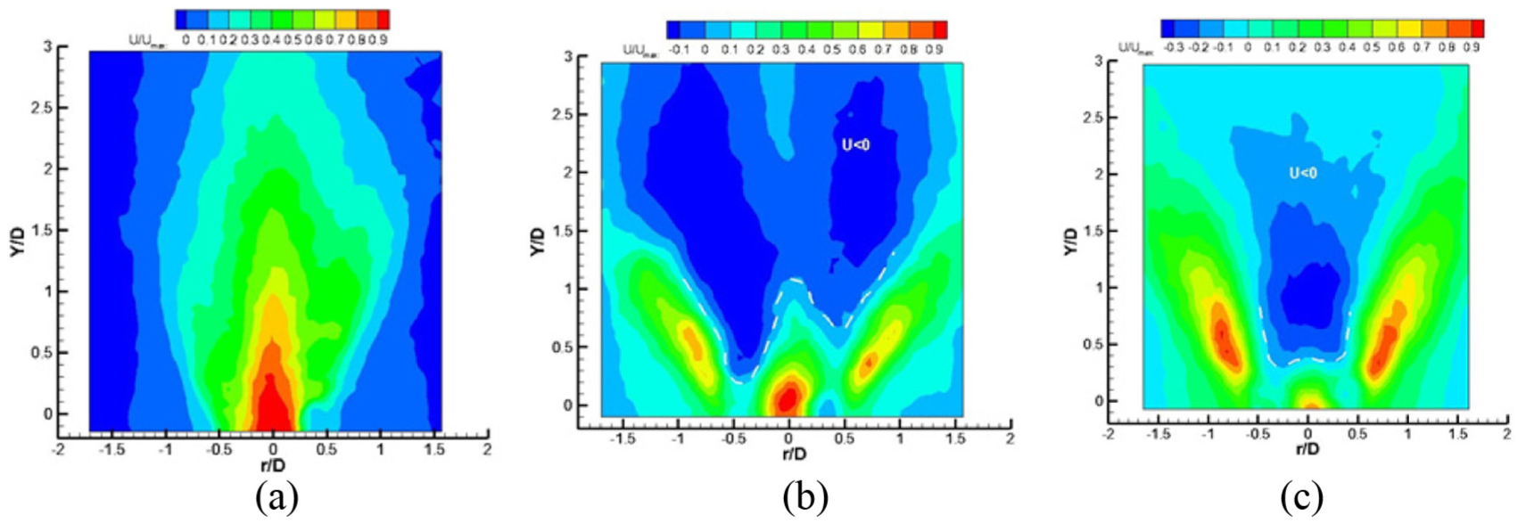
Normalized axial mean velocity contours for three swirl numbers: (a) Sn = 0.46, (b) Sn = 0.52, (c) Sn = 0.57.
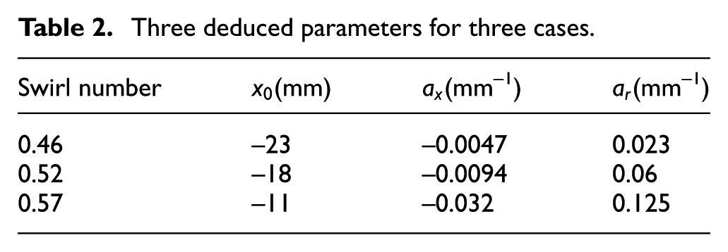
The centerline profiles for three different swirl numbers are compared in Figure 5. The normalized axial velocity collapses along the axial direction in the near field for all the cases. The velocity distribution is relatively flat for swirl number 0.46. In the far field, axial velocity is negative due to the formation of a weak recirculation zone for the swirl number 0.52 and 0.57. According to RK Cheng, 11 the following equation is applied to analyze the flow field


Normalized centerline profiles: (a)
Three deduced parameters for three cases.
The turbulent intensity is the normalized two-component turbulent kinetic energy, which is defined as
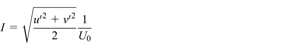
The turbulent intensity for the three swirl numbers are compared in Figure 5(b). The turbulent intensity for swirl number 0.46 has flat distributions. Distinctly, the turbulent intensity for swirl number 0.52 and 0.57 decreases linearly in the near field.
Radial profiles of the axial velocity and radial velocity at axial distance10 mm are shown in Figure 6. In the Figure 6(a), the

Normalized velocity profiles: (a) axial velocity profile and (b) radial velocity profile.
Flame stability
The primary task of the reacting test is to stabilize the flame at atmospheric conditions and verify the design of the burner. The tests are performed by maintaining a constant butane flow rate 0.08 g/s and increasing the air flow velocity. During the current operation of low-swirl burner, three distinguished flame regimes are observed. The changes in the flame shape with increasing air mass flow rate and constant fuel rate are shown in Figure 7.

Visible luminosity of flames: (a) 2.38 m/s, (b) 2.41 m/s, and (c) 2.54 m/s.
At the air flow velocity less than 2.38 m/s, the flame is attached to the rim of the burner. The blue flame indicates that premixed combustion occurs and heat mainly releases in the swirling and core straight jets. The air velocity is not high enough to lift off the flame. The influences of central channel jet and the annulus swirling jets are clearly observed in the flame. With further increase of air flow velocity, the flame progressively shortens. At the air flow velocity 2.41 m/s, the flame is lifted off the burner and has a W shape leading edge. The stagnation point is located downstream the burner exit. The transition between the above two combustion regimes occurs accompanied by fluctuations of the flame. When the air flow velocity is greater than 2.54 m/s, an apparent shrinkage in the lifted flame region occurs, and then the flame becomes to a bowl shape, indicating a significant change in the flame stabilization process. The stagnation line changes from a W shape to a planar shape. Further increase the air flow velocity dilutes the incoming mixture equivalence ratio. The flame becomes unstable and finally extinguishes. The regime under which combustion occurs is dominated by the fuel and air flow velocity.
To determine the flame stability of the burner designed in the current work, experiments are performed over a wide range of air inlet flow rate. Starting from an attached flame condition, lift-off and blow-out limits are determined by gradually increasing the air flow velocity while the fuel flow rate is held constant. The lean blowout ratio (LBO) limit is the region between the blow-off line and stable lifted flame line.
The maps of the flame regimes are plotted in Figure 8 as a function of the air flow velocity. The fuel flow rate remains 0.08 g/s for all the cases. For each radius ratio and blockage ratio, four swirlers with vane angle 37°, 40°, 42°, and 45° are examined. The swirl number of the four swirlers can be seen in Table 1. For radius ratio 0.56 and blockage ratio 0.64, the flame associated with the 37° vane angle is directly blown off without the lifting off regime. For other three vane angles, the low-swirl flame is first lifted off and then blown out. The region between the blowout and attached curve is the stable operating region. It is showed that the flame stability is not highly sensitive to the incoming velocity. The swirl angle does not have a significant impact on the flame stability as long as it is greater than a critical number. For the radius ratio 0.56 and blockage ratio 0.64, the critical number is 37° and the corresponding swirl number is 0.50. The flame of lifting off is an exceptional feature for LSC. This has significant engineering value because the combustor is insulated from the hot combustion gases.

Flame stability diagram: (a) R = 0.56, B = 0.64; (b) R = 0.56, B = 0.76; and (c) R = 0.64, B = 0.76.
The results of radius ratio 0.56 and blockage ratio 0.76 are given in Figure 8(b). The flame stability zones are similar in trend to the previous configuration except that the flame is also first lifted off and then blown out for vane angle 37°. Compared with Figure 8(a), increase of blockage ratio results in an increase of air flow velocity when lift-off and blowout occurs. This is attributed to the fact that the increase of blockage ratio means the fraction of annulus air flow increases. It results in an increase of tangential velocity and swirl number. Compared Figure 8(c) and (b), the flame stability follows a similar trend but the range between the blow-off and lift-off limit becomes narrower. The increase of radius ratio results in a decrease of air flow velocity when blow-off occurs. This is because increasing radius ratio is achieved by increasing the radius of central channel. Therefore, the air flow fraction through the central channel increases, which makes the flame prone to blow-off. It can be expected that increasing radius ratio requires a screen of lower blockage ratio to maintain the same flame stability range.
The flame chemiluminescence has been taken in order to characterize the overall flame structure. Then the flame length and spreading angle can be assessed on the basis of measurement of the chemiluminescence signals. The flame length is defined as the distance between the flame tip and the burner exit. The spreading angle refers to the included angle of two lines tangent to the enveloping line of the flame. Figure 9 shows the flame length and spreading angle variation with the air flow velocity for the radius ratio 0.56 and blockage ratio 0.76. As the air flow velocity increases, the flame length shortens abruptly and then slowly increases. The spreading angle of the flame increases abruptly and then decreases gradually. This is because the flame stabilization mechanism alters when the lift-off occurs. The results of other cases show in a similar manner and therefore for reasons of brevity, we do not reiterate the same discussion here.

Flame length and spreading angle of burner with R = 0.56, B = 0.76: (a) vane angle 37° and (b) vane angle 40°.
PLIF results
Instantaneous OH-PLIF images were also obtained to illustrate the flame structure. Two operating conditions are considered here. The fuel flow rates for both cases are still 0.08 g/s. The air flow velocities are 2.24 and 2.65 m/s. The radius ratio and blockage ratio of the burner is 0.64 and 0.76. The swirler of stagger angle 45° is used because it has the largest flame stability limit. The burner exhibits typical attached flame and detached flame under two conditions, respectively.
Four snap-shots of OH-PLIF images of an attached flame are shown in Figure 10. The dark portions represent the unburned mixture or surrounding air. The light blue portions are the products. The light intensity is proportional to the OH radical concentration, and hence burning intensity in the flame. Low OH zones exist in the inner part of the flame. The flame front is characterized by wrinkles especially in the top part and fluctuates slightly from frame to frame. Each snap-shot include long regions that convex toward the reactants, with sharp gaps in between. This results in locally intensive combustion in some regions and extinction in other regions. For attached flame, the OH-intensity and local burning rates are more uniform along the leading edge of the flame. A few green and red points that correspond to high OH concentration exist in the flame front owing to the high combustion intensity. Considering OH-PLIF gives only relative signals, it is unnecessary to quantitatively evaluate the OH field scale.
Four snap-shots of OH-PLIF for attached flames.
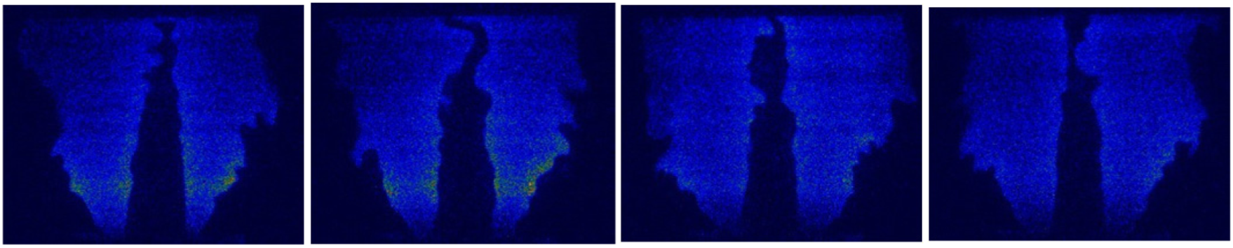
Four snap-shots of OH-PLIF images for the typical detached flame are shown in Figure 11. The leading edge of the flame has a “W” shape and is lifted from the burner exit. The flame is stabilized by the divergent flow instead of the burner rim. The leading edge of the flame front is located in the swirling streams and interacts with the flow field. The two V-shape leading edges propagate in the shear layer formed by the swirling and central streams, and finally merge together in further downstream. Compared with the attached flame, the lifted flame exhibits more wrinkles due to the high turbulent intensity. Thus the high levels of wrinkling in the flame front lead to the increase in the flame surface area and hence the turbulent flame speed. That is the reason why the length of the lifted flame is shorter than the attached flame. The local quenching and relight zones can be clearly seen in the Figure 11. This is because that strong shear mixing between the central channel and annulus swirling jets occurs. Significant vortex structures form and shed in the shear layer due to the velocity and pressure differences. This is so called the Kevin–Helmholtz instability.

Four snap-shots of OH-PLIF for detached flames.
The relevance of flow field to flame stability regime can be seen by comparing the PIV and PLIF results. The shape of zero velocity line, as shown in Figure 4(b) and (c), is similar to the leading edge of the flame front in Figure 11. Since the speed of burning hydrocarbon at atmospheric condition is only a few feet per second, 21 the flame propagates against the divergent flow until it settles the vicinity of recirculation zone boundary, where the premixed mixture has an opposite and equal velocity with the flame propagation speed. The divergence characteristic of flow field generated by low swirl is of paramount importance to achieve flame stabilization. More importantly, the flame position is able to self-adjust when the incoming flow disturbance occurs due to the linear decay of the mean axial velocity in the divergent flow pattern.
Conclusion
In this work, a low-swirl burner with different vane angle, radius ratio, and blockage ratio has been successfully developed. Reliable operation using butane has been achieved at standard atmospheric conditions. Initial laboratory experiments have been performed to investigate the flow-field and flame features of the present burner.
PIV system is used to capture the two-dimensional (2D) velocity distributions in the downstream of the burner at isothermal conditions. The results revealed that flow velocity decay linearly in the near field of the burner for all the cases. However, the flow structures in far field are significantly different. The position and size of recirculation varies abruptly with the swirl number.
The present burner exhibits three flame modes including attached flame, detached W shape flame, and planar flame. The swirl plays a dominant role on the flame mode, the stability limits, flame length, and spreading angle. The preferred operating condition corresponds to a lifted flame stabilized in the downstream of the injector by the swirling flow. If the incoming air velocity is not sufficiently high, the flame enters low-swirl injector, thus flashback occurs.
To facilitate the design work of the low-swirl burner, the next plan is to measure velocity field at reacting conditions and elevated pressure, temperature incoming flow conditions.
Footnotes
Handling Editor: Oronzio Manca
Declaration of conflicting interests
The author(s) declared no potential conflicts of interest with respect to the research, authorship, and/or publication of this article.
Funding
The author(s) disclosed receipt of the following financial support for the research, authorship, and/or publication of this article: This work has been funded by the National Natural Science Foundation of China under grant no. 51576164.