
Abstract
This article proposes a 3-PRC compliant parallel micromanipulator with 3 degrees of freedom. The piezoelectric actuator is adopted to drive the mechanism, and to compensate the stroke of the piezoelectric actuator, a new type of secondary lever amplification mechanism is designed. The kinematics model of the 3-PRC parallel micromanipulation platform is derived using vector method, and the forward and inverse kinematics solutions of a 3-PRC parallel micromanipulation stage are emphatically analyzed and then the Jacobian matrix of kinematics model and workspace are derived. Finally, the dynamic model is established by Lagrange equation, and the natural frequency of the mechanism is calculated. The modal analysis is carried out using finite element method. The results showed that the mechanism has a favorable performance on kinematics and dynamics, and this micromanipulator can achieve micro/nano level motion with high accuracy.
Introduction
With the development of micro/nano technology and robot technology, micromanipulation technology is becoming a hot spot that involves multi-disciplinary fields such as scanning probe microscopy (SPM), lithography, nano-manipulation and manufacturing, and biological science. 1 How to design a novel micromanipulator with compact size, larger stroke, higher precision, higher flexibility, and easier miniaturization is the key part of micromanipulation technology. 2 The compliant mechanism can realize the motion, force and energy transfer, and conversion mainly through the deformation of the flexible elements, while the traditional rigid components realize the specific movement and function through the connection of the motion pair and other components. 3 Compliant mechanisms have been widely used for fiber alignment, atomic force microscopy, and non-circular operation, which possess many advantages: excellent performance (such as high precision, light weight, and small friction), low cost (such as easy processing and less components), and easy miniaturization (such as micro/nano mechanical devices).4–7 The piezoelectric actuator is widely adopted to drive the micromanipulator, and to compensate the limited stroke of piezoelectric actuator, the amplifier mechanisms are adopted to meet the large stroke requirements.8,9 Utilizing an amplifier mechanism is the most effective way to amplify the stroke of micromanipulation stage, and the lever amplifier mechanism, bridge-type amplification mechanism, and Scott-Russell mechanism are commonly used in micromanipulation stages.10–12
In the study by Ding et al., 13 a 3-degree-of-freedom (DOF) planar micromanipulation stage with large rotational displacement for micromanipulation is designed with the workspace of 84.62 μm × 97.12 μm × 10.28 mrad, and the lever mechanism is adopted to magnify the stroke of the piezoelectric actuators in order to get a large workspace. Liu et al. 14 presented an XY parallel nanopositioner with symmetric and two-stage displacement amplifiers, and this mechanism has a large workspace more than 200 μm and a high natural frequency at about 760 Hz. In the study by Li and Xu,15,16 an XY totally decoupled parallel micromanipulator is presented based on flexure hinges, the bridge-type displacement amplifier is utilized for this stage to amplify the stroke of piezoelectric actuator, and the amplification ratio of bridge-type amplifier is approximately 6. M Muraoka and S Sanada 17 proposed a displacement amplifier for piezoelectric actuator based on honeycomb link mechanism, the maximum displacement of 400 μm along each X axis and Y axis, maximum resolution of 5 nm, and the natural frequency measured approximately 60 Hz. Yong et al. 18 designed a flexure-based XY Stage for fast nanoscale positioning; this stage uses a lever magnifying mechanism to amplify the output displacement of the piezoelectric stack and utilize the parallel quadrilateral mechanism to make the X axis and Y axis decoupled, and the natural frequency of the platform can reach up to 2.7 kHz. U Bhagat et al. 19 proposed a parallel piezoelectric platform based on right circular flexure hinge, which is capable of performing planar motion with 3 DOFs in X axis, Y axis, and θ, which is about 142 mm × 110 mm in size and the workspace is 39.0 μm × 25.0 μm × 0.9 mrad.
This article proposes a compliant parallel micromanipulator based on translational 3-prismatic-revolute-cylindrical (3-PRC) parallel mechanism that can realize three translational motion in space. The novelty of this mechanism employs flexure-based joints for the purposes of avoiding assembly errors and employs secondary lever amplifier to compensate the stroke of the piezoelectric actuator. By the way, the proposed 3-PRC mechanism has the benefit of compactness size, large amplification ratio, and good decoupling characteristic compared with the previous 3-PRC mechanism.20,21 The remainder of this article is organized as follows: a novel 3-PRC-compliant parallel micromanipulator is proposed in section “3-PRC-compliant parallel micromanipulator design”; the structure of secondary lever amplifier is introduced in detail, the amplification ratio is calculated by lever principle and the results of simulation by ANSYS software is used to verify the theoretical calculation in section “The secondary lever amplifier design”; the kinematic analysis of this manipulation stage is conducted in section “Kinematics model of the 3-PRC-compliant parallel micromanipulator”; in section “Dynamics model of the 3-PRC-compliant parallel micromanipulator,” the dynamic characteristics and performance of this stage are evaluated. Finally, the conclusions are concluded in section “Conclusion.”
3-PRC-compliant parallel micromanipulator design
As shown in Figure 1(a), the micromanipulator is composed of a fixed base, a mobile platform, and three limbs with identical PRC structure, and the size of the entire 3-PRC parallel micromanipulator is 174.50 mm × 174.50 mm × 174.50 mm. The structure of each limb is depicted in Figure 1(b), and the secondary lever amplifier as a prismatic (P) hinge is fixed at the base and actuated by a PZT actuator. Cylindrical (C) joint is equivalent to revolute (R) joint and prismatic (P) hinge in axial direction, combined with revolute (R) joint as passive joints connected with mobile platform. In order to generate a cuboid shape workspace of the micromanipulator, each limb is designed as parallel mechanism to improve the rigidity and kinematics performance of the micromanipulator. Three limbs are assembled in the orthogonal design method to eliminate or reduce parasitic motions of the end-effector (mobile platform).

3-PRC-compliant parallel micromanipulator: (a) the structure of micromanipulator and (b) the structure of limb.
The secondary lever amplifier design
According to the lever principle, the novel secondary lever amplifier is designed to compensate the stroke of the piezoelectric actuator and then enlarge the mobile platform workspace. As illustrated in Figure 2(a), to reduce the overall size of the amplifier structure, the piezoelectric actuator was installed inside it. And the amplifier is designed as a symmetrical (parallel) structure for the purposes of eliminating the parasitic movement and improving the output accuracy of the amplifier. The novel amplifier fully owns both advantages of lever amplifier and bridge type amplifier which are with simple and compactness structure, good linearity.

The secondary lever amplifier: (a) the novel secondary lever amplifier, (b) the geometric parameters of amplifier, and (c) the right circular flexure hinge.
As shown in Figure 2(b), O1 point and O2 point are the level pivots, O3 point is the input side of PZT actuator, O1AB is the first level and O2CD is the second level, and the piezoelectric actuator exerts a small displacement at O3. And then the output terminal E obtains ampliative displacement under the effect of O1AB and O2CD. As shown in Figure 2(c), all joints in the micromanipulator are expressed by the straight circular flexure hinge.
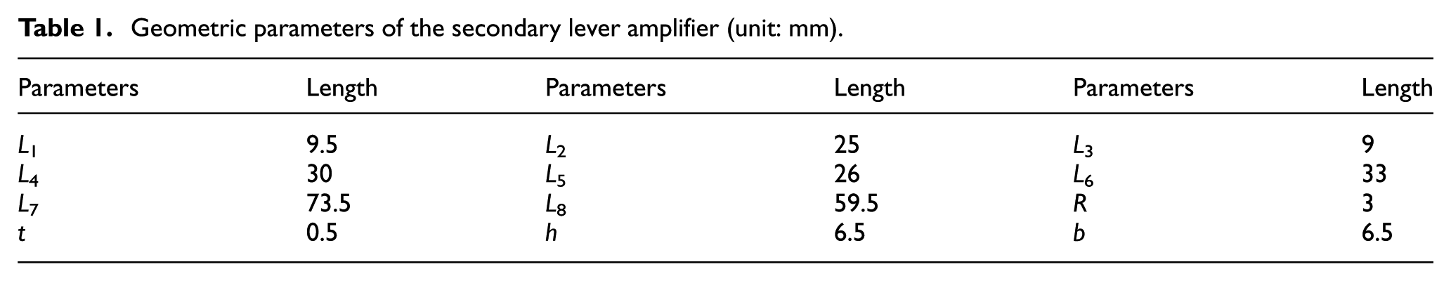
The geometric parameters are shown in Table 1, and the first lever and secondary lever theoretical amplification ratio A1 and A2 can be expressed as
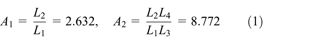
Geometric parameters of the secondary lever amplifier (unit: mm).
The theoretical output displacement of the secondary lever amplifier can be calculated by the following equation

The ANSYS software is used to verify the theoretical amplification ratio and the deformed shape is illustrated in Figure 3. The finite element analysis (FEA) results show that the amplification ratio Aact


Deformation of the novel secondary lever amplifier.
Due to the elimination of the parasitic movement of the X axis, the theoretical amplification ratio A2 of Y axis is different from the FEA result, but the result gives a very small percentage of error rate 6.01%.
Kinematics model of the 3-PRC-compliant parallel micromanipulator
The simplified computer-aided design (CAD) model of a 3-PRC-compliant parallel micromanipulator limb is graphically shown in Figure 4(a), and the schematic diagram is illustrated in Figure 4(b), each limb connects the fixed base to the mobile platform through a P joint, an R joint, and a C(R-P) joint in sequence, where the P joint is driven by PZT actuator mounted on the fixed base. The mobile platform is attached to the base by three identical PRC linkages. We assign a fixed Cartesian frame
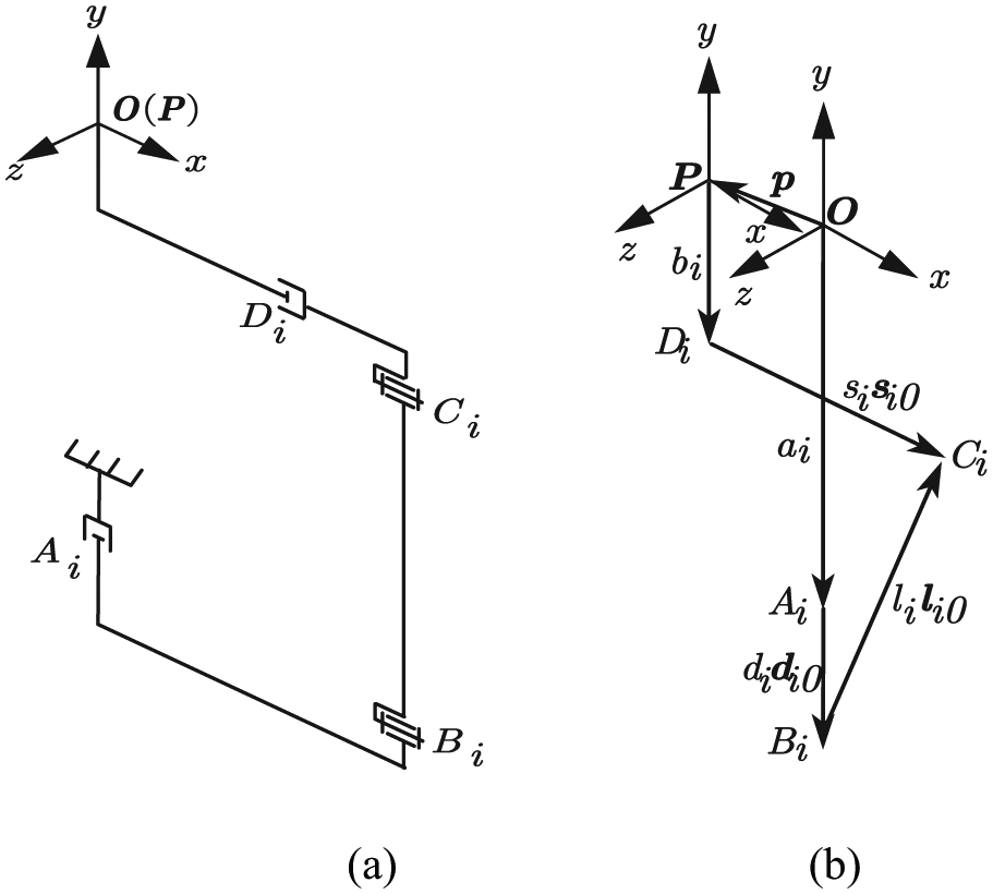
3-PRC model of limb: (a) the simplified CAD model of limb and (b) schematic diagram of a 3-PRC limb.
With the vectors representation shown in Figure 4(b), the vectors can be expressed as

where
Inverse kinematics modeling mobility
As shown in Figure 4(b), a vector-loop equation can be written for ith limb of the 3-PRC model as follows

where

with the notation of

In view of equation (5), a necessary calculation leads to the inverse displacement solutions
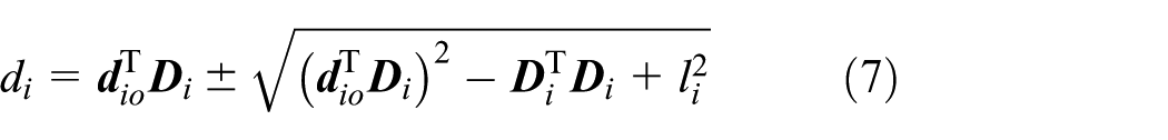
We can observe that there exist two solutions for variable, only the positive square root in equation (7) is selected
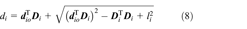
which can be expanded into the following forms

From equations (2) and (9), we can derive that

which is inverse kinematics of the 3-PRC-compliant parallel micromanipulator.
Velocity analysis
Both sides of formula (5) are multiplied by si

And then it can be expanded into the following forms

Following formula (12), differential equations with respect to time

Formula (13) can be written as

where

Substituting equation (6) into equation (5) and differentiating the expression with respect to time leads to

where
Dot-multiplying both sides of equation (16) by

Substituting equation (8) into equation (5), the unit vector expression for connecting the R joint Bi and the R joint Ci in the fixed coordinate system

Writing equation (17) three times, once for each i = 1, 2, and 3, yields three scalar equations which can be written in the matrix form

where the matrices

the following velocity equations can be derived from equation (19)

where

is the 3 × 3 Jacobian matrix of a 3-PRC-compliant parallel micromanipulator, and it plays an important role in kinematic analysis.
It can be expanded into the following form

Forward kinematics modeling mobility
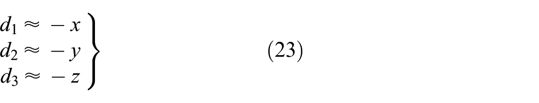
Considering the units for the actuated joint variable di and the mobile position x, y, z of the micromanipulator are micrometers, where the unit for l is millimeter, the Jacobian matrix can be approximately written as

Equation (9) can be written as
and then

substituting equation (6) into equation (5)

So, the relationship between input stroke of piezoelectric actuators and the position of the central platform can be written as follows

Workspace analysis
The workspace of the 3-PRC-compliant parallel micromanipulator can be calculated by the aforementioned kinematic analysis. Actually, the reachable workspace of the manipulator not only depends on the above equation (10) but also has the relationship with material property. The following list is the constraint condition of 3-PRC-compliant parallel micromanipulator

where qi denotes the output displacement of the piezoelectric and l is the length of the R-C leg. Substituting equation (27) into equation (10), the workspace of the micromanipulator can be obtained by MATLAB, and the three-dimensional (3D) workspace is graphically illustrated in Figure 5. From the simulation results, the reachable workspace of the end-effector is a hexahedron.
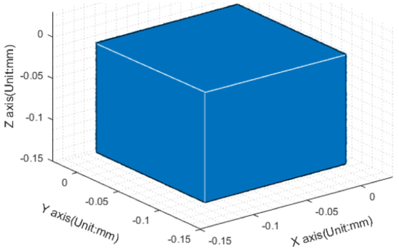
Reachable workspace of the micromanipulator.
Dynamics model of the 3-PRC-compliant parallel micromanipulator
Due to the merits of eliminating the consideration for the forces of constraint, Lagrange’s equation of motion is adopted for the dynamics modeling of the 3-PRC-compliant parallel micromanipulator. In order to obtain the dynamics model, both the potential and kinetic energies of the micromanipulator should be expressed in terms of the selected coordinates and their derivatives, and the variable q is chosen as the generalized coordinates. And then assume that all of the potential energy come from the elastic deformations of flexure hinges and the gravity of the micromanipulator. The mass distribution of each component is shown in Figure 6.

The mass distribution of components.
Potential and kinetic energy of the micromanipulator
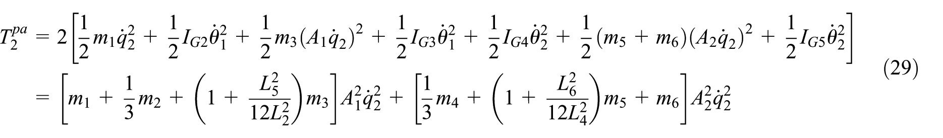
The elastic potential energy for the second limb of secondary lever amplifier can be expressed as

where k is the rotation stiffness of flexure R hinges, which can be expressed as

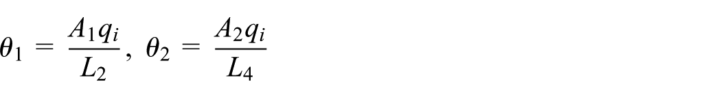
and the first lever angle θ1 and secondary lever angle θ2 can be expressed as
the kinetic energy of the secondary lever amplifier can be calculated by the following equation
where rotary inertia of the components can be expressed by

thus, the energy function for the three limbs secondary lever amplifier of the micromanipulator can be computed by

The potential energy for the second R-C leg of micromanipulator can be obtained by
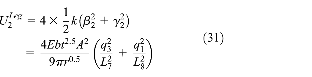
where

The kinetic energy of the second R-C leg can be expressed as

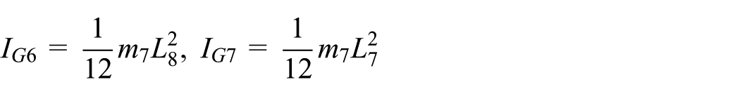
where rotary inertia of the components can be expressed by
thus, the energy function for the three limbs R-C leg of the micromanipulator can be computed by

The kinetic energy for the mobile platform is expressed by

The potential energy of the entire micromanipulator due to the gravitational force should be considered

Lagrange’s function for the micromanipulator can be generated

Lagrange’s equation of motion can be derived based on the generalized coordinates q, according to

where qi denotes the ith generalized coordinate and Fi is the ith actuation force.
The generated dynamic equations take on the following form

where

where m0 is the mass of the mobile platform.
Modal analysis of the micromanipulator
The modal analysis is necessary for the design of 3-PRC-compliant parallel micromanipulator as far as the control frequency is concerned, and the dynamic equation of undamped free vibration of the micromanipulator system can be expressed as

The condition of non-zero solutions for equation (39) can be derived by

where
The natural frequency of the micromanipulator can be calculated by

The micromanipulator material adopts Al(7075-T6), the density is 2810 kg/m3, Young’s modulus E is 71.7 GPa, and Poisson’s ratio is 0.33. The first six modal shapes are illustrated in Figure 7, and the first six natural frequencies of modal analysis are listed in Table 2. It is observed that the first natural frequency obtained by ANSYS software agrees well with the value calculated from equation (41). The deviation between the calculated and the simulated nature frequency is only 2.54%, which verifies the validity of the performance dynamic modeling for the 3-PRC-compliant parallel micromanipulator.
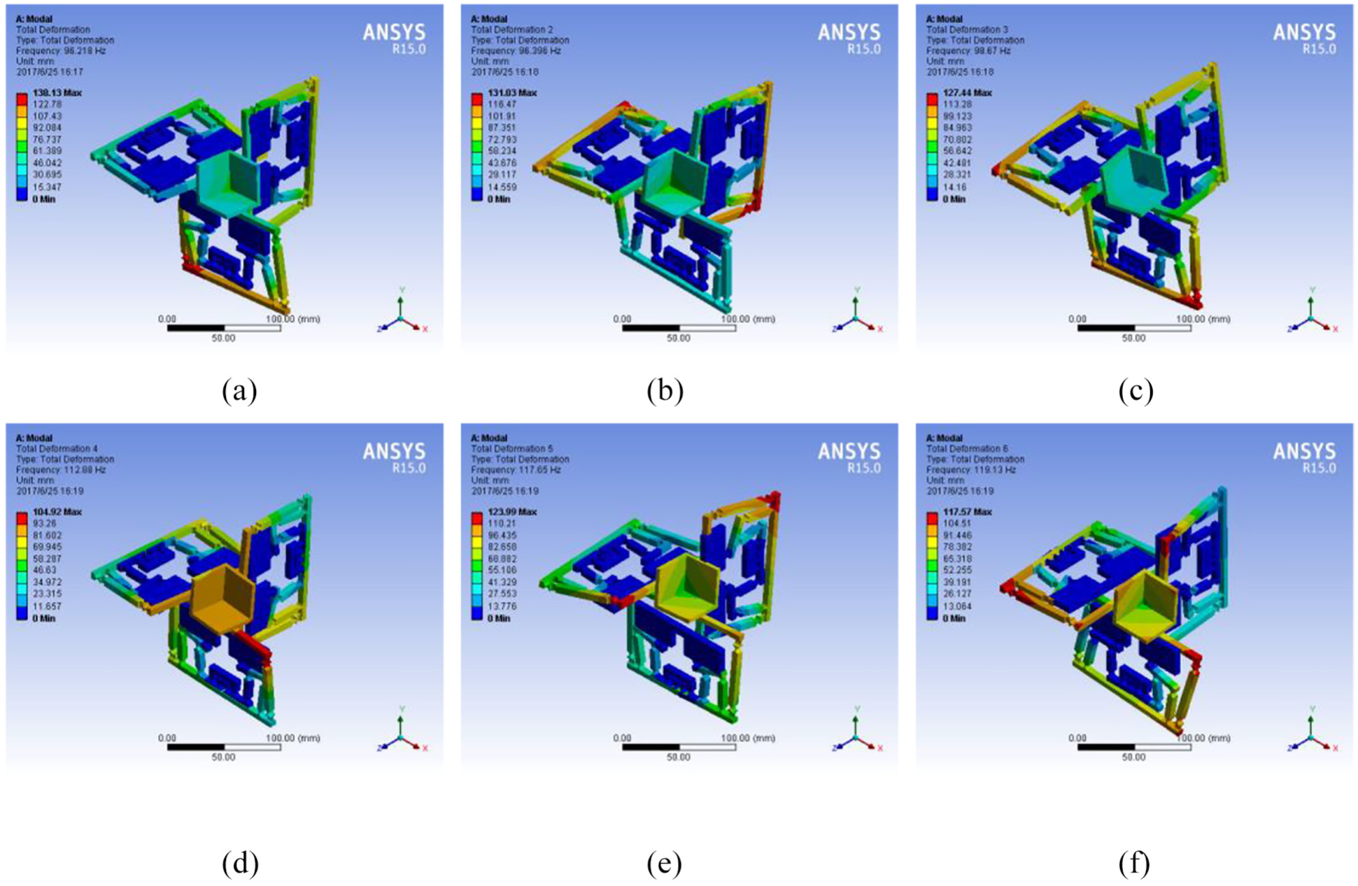
The first six modal shapes: (a) modal shape 1, (b) modal shape 2, (c) modal shape 3, (d) modal shape 4, (e) modal shape 5, and (f) modal shape 6.
The first six natural frequencies.

Conclusion
A compliant parallel micromanipulator based on translational 3-PRC parallel mechanism that can realize three translational DOFs in space is designed and analyzed in this article. The mechanism employs secondary lever amplifier to compensate the stroke of the piezoelectric actuator, and the deviation between the calculated and the simulated amplification ratio of the amplifier is only 6.01%. The inverse and forward kinematics and Jacobian matrix have been derived, and the reachable workspace is generated by simulation analysis. The dynamics analysis of 3-PRC micromanipulator is also performed in this article, and Lagrange’s equation of motion is adopted for the dynamics modeling of the micromanipulator. The natural frequency is calculated, which is verified by the modal analysis via Workbench software, and the deviation between the calculated and the simulated nature frequency is only 2.54%. The results show that this micromanipulator has a favorable performance on kinematics and dynamics, and this micromanipulator can achieve micro/nano level motion with high accuracy. To further validate the performance of proposed mechanism, the experimental studies will be conducted in next stage, including prototype fabrication and workspace validation.
Footnotes
Handling Editor: Mario L Ferrari
Declaration of conflicting interests
The author(s) declared no potential conflicts of interest with respect to the research, authorship, and/or publication of this article.
Funding
The author(s) disclosed receipt of the following financial support for the research, authorship, and/or publication of this article: This paper was co-supported by National Natural Science Foundation of China (Grant No. 51575544) and Tianjin Natural Science Foundation Key Program (Grant No. 16JCZDJC38000).