
Abstract
A new nonlinear hysteretic model with considering the loading, unloading, and reloading processes is developed based on Drucker–Prager yield criterion and finite-element analysis. This model can be used for multiple repeated elastic–plastic normal direction contact problems between two identical spherical geomaterials. After examining the influence of material properties, strain hardening, and loading histories, we found that the hysteretic phenomena (represented by residual displacement and plastic work) become weak after the first cycle, and the subsequent cycles step into elastic shakedown state eventually. A critical number of cycles can be used to estimate the state of ratchetting, plastic shakedown, as well as elastic shakedown. It also found that the subsequent curves will be stiffer than the previous ones, especially when the yield strength is high and ratchetting effect is not strong. This new model can be used for a wide range of geomaterials under different loading levels, and it can also be extended to describe the constitutive behavior of spheres under earthquake as well as aftershocks.
Keywords
Introduction
Interaction between two spheres is the most fundamental problems for discrete geological material simulation, among which repeated loading and unloading is especially important for dynamic action, such as compacted discrete rock mass or soil under seismic force.
Usually, very simple linear models of contact, like linear viscoelastic models, are used in Discrete Element Methods, which account for more than 60% of all cases. 1 The main disadvantage of non-hysteretic models is their artificial assumption of force–displacement behavior, which would not guarantee their accuracy to describe the overall macroscope response of particle systems under repeated loading in elastic–plastic regime.
With regard to the interaction without cohesion, it has been realized that hysteretic models consisted of springs and sliders would be more physically intuitive than other types of models with dampers for the energy dissipation. The contact zone is under locally plastic deformation, rather than the artificial damper behavior. 2
Although many contact models of the hysteretic type have been developed for corresponding materials separately,3–7 relatively few attentions have been paid to the unloading and reloading responses of elastic–plastic deformation especially, which is essential for cyclic loading simulation between spheres.
The main difficulties for cyclic loading model with hysteretic law result from the definition of stiffness coefficients and assessment of the evolution of stress state during the unloading and reloading processes. Literatures concerned include the elastic–plastic indentation of rigid sphere to compliant base and interference between two flexible spheres, which could be mutually emulated substantially.
Generally speaking, the understanding of unloading process goes through elastic assumption to elastic–plastic verification. Assuming the unloading behavior purely elastic, Johnson 8 proposed the analytical model of unloading for elastic–plastic indentation. Later, the model had been modified by Li and Gu 9 based on the superposition of Steuermann solutions instead of the original contact surface curvature. That modification made it more closely fit with the numerical results with large plastic deformation. Yan and Li 10 studied the deformation of a rigid sphere under cyclic indentation. In their study, an elastic–perfectly plastic half-space was adopted and they found that the deformation during unloading from a contact beyond the elastic limit was perfectly elastic and the reloading curve was the same as the unloading curve. The material of the half-space used by them represented a typical steel material, with high elastic modulus and yield stress. However, it is still unclear whether the unloading and reloading response would be different for other materials with low elastic modulus and yield stress.
Song and Komvopoulos 11 examined the unloading behavior of indented elastic–plastic materials as well as the evolution of plasticity due to four consecutive indentation cycles by finite-element analysis (FEA) and found the occurrence of plastic deformation during unloading was attributed to the effect of the residual stresses in the elastic material surrounded by the plastic regime. Also, they deduced that elastic shakedown behavior (i.e. dynamic creep, creep associated with fatigue, or deflection stability) would be characterized by the elastic–plastic deformation for material with high effective elastic modulus-to-yield strength ratio (E*/Y) under repeated loading–unloading cycle, while it would keep ratcheting deformation for material with low E*/Y.
Concerning the spherical interference, Etsion et al. 12 studied the unloading response of an elastic–plastic sphere contacting with a rigid plane by FEA and noticed that the purely elastic unloading was just one of the extreme case, and they concluded that all subsequent load–unload process after the initial loading–unloading cycle would be fully elastic. They proposed an unloading model of the power law relation with nonconstant exponent, which was also been adopted by Song and Komvopoulos. 11 Jackson et al. 13 found high residual stresses remained after an elastic–plastic hemispherical contact being unloaded. Kadin et al. 14 presented the numerical results of two successive loading and unloading cycles on the same model as Etsion et al. 12 and inferred that the secondary plastic flow might reach a steady state and the successive loading–unloading cycles become fully elastic from the evolution of equivalent von Mises stress distribution. Later, Zait et al. 15 extended the unloading contact model of Etsion et al. 12 including stick contact condition.
All the above-mentioned results are mainly fit for metallic material following the von Mises yield criterion (i.e. Maxwell–Huber–Hencky–von Mises theory), which are not suitable for more complicated geo materials with hydrostatic pressure dependence. Besides, the reloading model based on reliable FEA results has not been put forward, which is crucial for cyclic loading problems.
Although Sadd et al. 16 developed a nonlinear hysteretic contact law including loading, unloading, and reloading stages for dry cohesionless granular media simulation based on photo-elastic experiment, the inter-particle contact behavior did not exceed the elastic regime substantially.
Kostek 17 presented a nonlinear mathematical model describing the hysteresis of dry contact of rough planar surfaces loaded in the normal direction, which is hard to transform to spherical contact.
Therefore, the main purpose of this article is to develop unloading and reloading models for geomaterial under cyclic loading and with elastic–plastic deformation. Also, the influence of material properties and loading histories on the evolution of elastic–plastic deformation will be examined. This article is structured as follows. FEA model and yield criterion are described in sections “Numerical model” and “Material constitutive model,” respectively. Schematic contact model is presented in section “Contact model,” and loading model of the first cycle, unloading model, and reloading model are discussed in sections “Loading model,”“Unloading model,” and “Reloading model” individually. Influence of material properties and loading history on loading–unloading curves is discussed in sections “Influence of material properties” and “Influence of loading history,” respectively. Finally, conclusions are drawn in section “Conclusion.”
Contact models
Contact model
Figure 1 presents the contact force F and displacement δ curve for elastic–plastic contact between two spheres. The loading process O → A can be predicted accurately by hysteretic model

Schematic illustration of contact force versus displacement of loading, unloading, and reloading processes of elastic–plastic contact.
The contact loads in the unloading process A → B and reloading process B → C are affected by the initial loading level
The schematic model assumes that the reloading behavior is elastic. The reloading response is elastic shakedown under repeated loading, which can be simplified to elastic behavior when the incremental plastic strain and plastic work of the subsequent cycles are negligible, according to the shakedown theorems. This assumption will be further illuminated in section “Influence of loading history” in the following.
The schematic model presented is similar to the model proposed by Sadd et al. 16 in terms of the schematic form, while the latter is dependent on the previous loading and unloading paths. In the presented reloading model, only the final states of the previous loading and unloading processes, that is, the maximum loading level and the residual displacement of the previous unloading, are concerned, which makes it simpler without losing accuracy.
Numerical model
The interaction of two identical spheres (ball–ball interaction) is equivalent to a sphere acting on a rigid flat surface (ball–wall interaction) due to the symmetry of ball–ball interaction, while the displacement of ball–wall interaction is half of ball–ball interaction. In order to improve the computing efficiency without losing the accuracy, an axisymmetric ball–wall model is adopted from the nonlinear finite-element package ABAQUS 6.14.
The finite-element mesh shown in Figure 2(a) and (b) represents an axisymmetric model of hemisphere (with radius R = 0.1 m) with 32,828 four-node bilinear quadrilateral elements (CAX4R element). The hemisphere is divided into three different mesh density zones. Zone I, within 0.1R from the sphere tip, has as small mesh size as 0.0001 times the yield contact radius
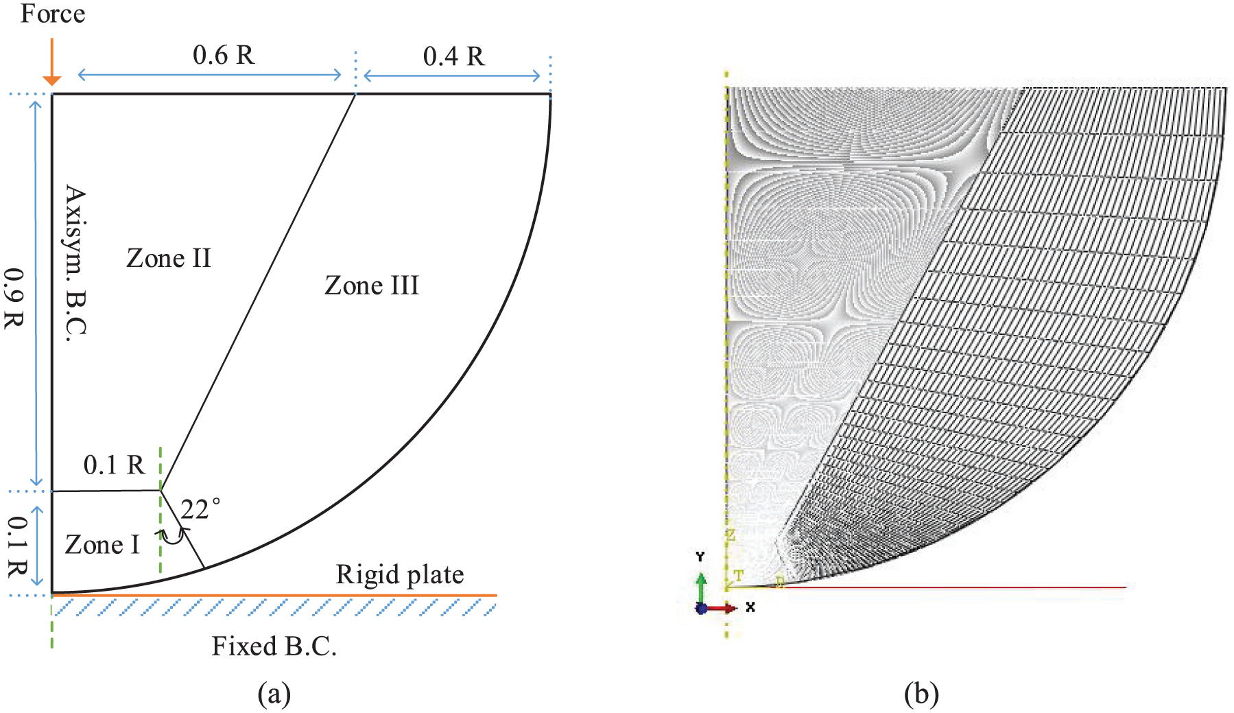
(a) Schematic model of spherical contact and (b) finite element meshing.
The boundary conditions are also shown in Figure 2(a). The rigid plate is fixed on the bottom, thus only compliant deformation of the sphere allowed. The axisymmetrical boundary is applied to the center of the hemisphere, which prevents the moving of nodes in the radial direction. Contact force is applied to the center of the hemisphere. The vertical displacements of those nodes at the top are constrained by multi-point constraints (MPCs), and the interaction between ball and the wall is frictionless and set to be “surface-to-surface” discretization. The normal contact force F increases from 0 N to the target value with a constant rate in 3 min and then decreases back to 0 N steadily in 1 min, which makes a loading–unloading cycle.
The contact model has been verified by comparing the calculated results with the analytical output of Hertz solution in the elastic regime, as well as the analytical solution of the incipient yield force and displacement from the D-P criterion. Data for sandstone have been used for those verifications. Basically, FEA results closely agree with the Hertzian solution in the elastic regime, and the difference between the numerical and analytical results of the elastic–plastic constitutive model at the incipient yield point is less than 5%, thus the contact model presented is suitable for further exploration in the elastic–plastic regime, according to Vu-Quoc et al. 4
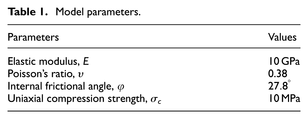
The material properties of Table 1 can be referred for the uniaxial compression test of sandstone, as shown by Goodman. 18
Model parameters.
Material constitutive model
Yield criterion and hardening rule
The chosen yield criterion is the Drucker–Prager (D-P) linear yield function with associated plastic flow, which can be written as

where q is the generalized shear stress and defined by the second invariant of the deviatoric tensor J2 as

Schematic of hardening and flow for the linear D-P model in the p-q plane.
If hardening is defined by the uniaxial compression test, then the initial yield surface can be defined as
where
The strain-hardening curve as well as its parameters for geomaterial can be obtained and implemented to predict stress–strain responses closely agreeing with the experimental tests, according to the method proposed by Jiang and Wu. 19 The actual exponential strain-hardening relationship can be idealized and approximated by bilinear model. 20 Thus, the linear isotropic hardening curve can be shown as Figure 4, with the ratio of hardening modulus to elastic modulus m. m is also called strain-hardening parameter. 21 For the perfectly plastic case, m equals to 0, and for the elastic case, m equals to 1. For simplification and universality, only the fully plastic case has been chosen for the contact model proposed, but the influence of strain-hardening parameter on contact response will be discussed.
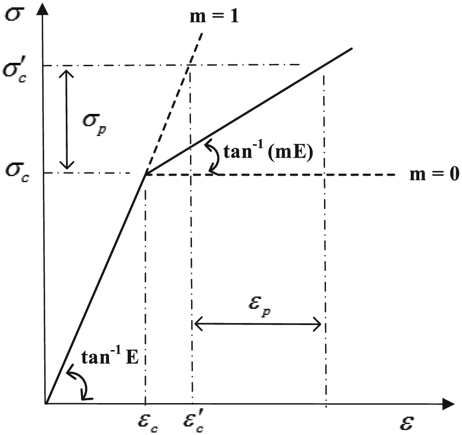
Stress σ versus strain ε for elastic linear-strain-hardening plastic model.
As shown in Figure 4, the yield stress with isotropic hardening effect for the elastic linear-strain-hardening plastic material can be written as

where E is the elastic modulus,
Thus, the subsequent yielding surface in Figure 3 can be defined as

Flow rule
The associated flow potential, g, for the linear D-P model can be written as

Isotropic strain-hardening defined in uniaxial compression can then be modeled in terms of the incremental plastic strain as

where

Results and discussion
The loading, unloading, and reloading processes of spherical contact have been studied, considering the influence of material properties and loading history.
Spherical contact model
Loading model
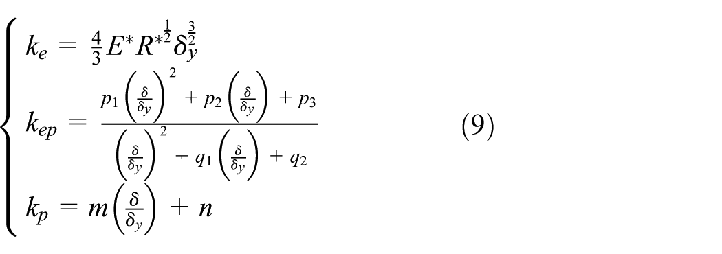
The contact model for geomaterial can be summarized as equations (8) and (9)
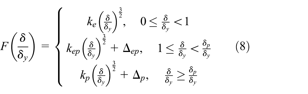
where stiffness coefficient is
In this example, the pseudo stiffness coefficients in these three regimes can be regressed and expressed as equation (10), with the compensation of errors

The compliance curve predicted by this model is shown in Figure 5. The present model adopts the Hertzian solution in the elastic regime, as well as the best-fit curves in the elastic–plastic regime and in the fully plastic regime, with a small tuning at the boundary of their transition to eliminate the deviation caused by finite sliding contact-tracking approaches. The present model closely agrees with the FEA results. Moreover, it is more physically intuitive than those regressive models totally dependent on FEA results or analytical models constrained by some assumptions for the plastic deformation.

The curve for the proposed model compared to the FEA results.
Unloading model
The numerical results as well as the empirical relation of unloading process initiated from elastic–plastic deformation (contact force F lies between the incipient yield force Fy and the incipient fully yield force Fp) and fully plastic deformation (contact force F lies above the incipient fully yield force Fp) are shown in Figure 6. As claimed by Song and Komvopoulos,
11
plastic deformation also occurs during unloading, which makes the load–displacement behavior of unloading process nonlinear and strongly affected by the initial loading level

The exponent n can be expressed as the function of

where

Contact force versus displacement of unloading process (F is the contact force, Fy is the incipient yield force, and Fp is the incipient fully yield force).
It should be noticed that n = 1.521 when
The residual displacement can also be predicted by the level of previous unloading displacement according to FEA results (see Figure 7(a) and equation (13))


(a) Normalized residual displacement and (b) normalized plastic work versus normalized maximum displacement of unloading process.
Similarly, the power function of normalized maximum displacement used to express the normalized plastic work closely agrees with the finite-element method (FEM) results (see Figure 7(b))

where Wp is the plastic work and Wtotal is the total work the normal force has done.
Reloading model
Figure 8(a) presents the normalized contact force–normalized displacement results for reloading process with the maximum initial loading (Fmax) is 6000 N, which attempts to be higher than the subsequent loading level. With the increase in the maximum initial loading, the residual contact area increases, which makes the reloading curve hardened.

(a) Normalized contact force versus normalized displacement and (b) contact force versus displacement of reloading process (solid line: FEM results; Dashed line: fitted by equation (12)).
Similar to the unloading model, the reloading model can also be expressed as a power function as the unloading model

The exponent m can be expressed as the function of
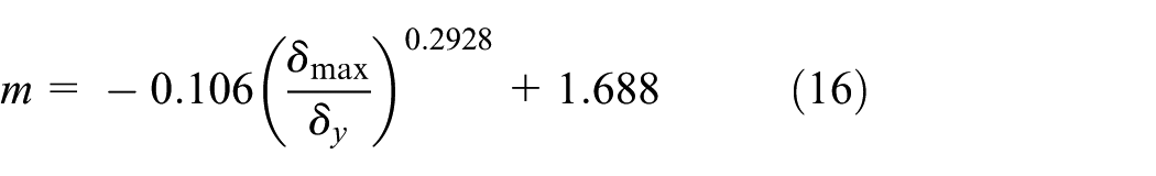
The fitted function closely agrees with the FEM results, especially when the contact load is not too large, as shown in Figure 8(b).
It should be noticed that the reloading process predicted by equations (8), (11), and (13) is only suitable for those interaction without seriously plastic flow or particle breakage. Parameters in equations (10), (12), and (14) are related to material properties, which can be determined from experimental calibration tests or numerical calculations.
Influence of material properties
We explored the influence of elastic modulus E, compression yield stress

Normalized contact force (the ratio of normal force F to maximum force Fmax) versus normalized displacement (the ratio of displacement δ to maximum normal displacement δmax) of loading and unloading processes with elastic modulus in the range of 1–100 GPa for Fmax = 6000 N.
Figure 10 compares the results from different normalized parameters. We can see that the nonlinear spring stiffness monotonically increases with the increase in elastic modulus and decreases with the increase in inner frictional angle and strain-hardening parameter, but almost keep the same with the changing of compression yield stress. Normally, the incipient yield force Fy only depends on the inner frictional angle and the compression yield stress. Thus, it is reasonable to see that the maximum normalized load remains constant for different elastic modulus and strain-hardening parameter, while vary with the inner frictional angle and compression yield stress in Figure 10. Similar to the findings from Shankar and Arjun, 24 our numerical results of isotropic hardening are consistent with analytical illustration in equation (3) and Figure 4, that is, the material behavior changes from fully plastic to perfect elastic with the strain-hardening parameter m transforming from 0 to 1.

Normalized contact force (the ratio of normal force F to incipient yield force Fy) versus normalized displacement (the ratio of normal displacement δ to incipient normal displacement δy) of loading and unloading processes (a) with elastic modulus from 1 to 100 GPa, (b) with inner frictional angle from
It should be noticed that the phenomenon of overlapping of the force–displacement curves has not been seen here as the metallic material following von Mises criterion with the change in material properties, which just indicates that the model derived from D-P criterion is more sensible to material properties than that from von Mises criterion. Actually, the whole overlapping of the force–displacement should never been expected for two different kinds of material, even for metallic material.2,11 According to many unloading and reloading simulating results, the unloading and reloading models are still validated for other geomaterial with different frictional angle and yield stress, after the constants in equations (12) and (16) being adjusted by numerical or test results, which is the specific property of geomaterial with D-P criterion and can be easily implemented.
Influence of loading history
To get full insight into the effect of loading history on elastic–plastic response of geological material, 10 consecutive cycles are simulated for maximum loading force Fmax = 3000 N (repeated loading). Seven other consecutive cycles with the maximum loading force monotonically increasing from 100 to 3000 N (monoincreasing loading) and decreasing from 3000 to 100 N separately have also been calculated (monodecreasing loading). Considering the sensitivity of material properties on residual displacement and plastic work, two levels of uniaxial compression stress are chosen for analysis (i.e. σc = 10 and 1 MPa), instead of the effective elastic modulus used by Song and Komvopoulos. 11
Repeated loading
The relationship between contact force and displacement of the first six cycles are shown in Figure 11(a) and (b). When the uniaxial compression yield stress is at a high level (e.g. 10 MPa), the subsequent reloading and unloading behaviors are hardened after the initial loading process, which is similar to the hardening effects shown in Figure 10(d), but the residual displacement continuously increases with monodecreasing increment, as shown in Figure 11(a).

Contact force versus displacement for repeated loading: (a) σc = 10 MPa, (b) σc = 1 MPa, and (c) time history of loading.
According to the shakedown theorems,20,25,26 when both of the incremental plastic strain
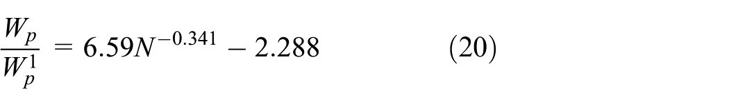
Because of the rapid decrease in residual displacement and plastic work after the initial cycle, the ratios of residual displacement and plastic work of subsequent cycles to that of the first cycle are examined for clearness (see Figure 12(a) and (b)). When the compression yield stress of the sphere is 10 MPa, those two types of ratio are power law relation of the cycle number N separately, which are given by equations (17) and (18). When the compression yield stress is 1 MPa, those two types of ratio are fitted by equations (16) and (17) individually


where

(a) Ratio of subsequent residual displacement and (b) plastic work to those of the first cycle separately versus cycle number for repeated loading.
The critical cycles, that is, the cycle when the incremental plastic strain or incremental plastic work is zero, can be deduced by those ratio functions. Both critical cycles calculated by equations (17) and (18) are 11, while the critical cycles calculated by equations (19) and (20) are 17 and 23, respectively. Following the shakedown theorems, the sphere with higher compression yield force more easily transforms to elastic shakedown behavior. For the sphere with lower compression yield force, it will experience ratchetting (i.e.

It should be noticed that equations (17)–(20) are fitted from results of FEA, which show the influence of material properties on shakedown behavior of spherical contact. No limitation has been seen for the power law relationship, but the critical cycle will change with different yield strength.
The response of spherical contact starts from plastic flow and ends with elastic shakedown, in agreement with the finding of Kadin et al. 14 The detailed paths from plastic deformation to elastic shakedown response have been revealed, which may reflect the dominant effect of shakedown or ratchetting, as is shown in Figure 11(a) and (b).
Also, the geomaterial with D-P criterion used here does not so easily transform to elastic shakedown state under repeated loading as the metallic materials with von Mises criterion used by Kadin et al. 14 and Song and Komvopoulos. 11 For their results, the earliest elastic shakedown behavior emerges at the second cycle, whereas in this study more than 11 cycles are needed.
Monotonically decreasing loading
The loads applied for monotonically decreasing loading are as follows: after the initial cycle of maximum loading force 3000 N, the maximum reloading forces from cycle 2 to cycle 7 are 2500, 2000, 1500, 1000, 500, and 100 N.
The reloading responses for materials with high or low level of compression yield strength follow the same way: the reloading process is rapidly stabilized to elastic shakedown response, as shown in Figure 13. For most materials exhibiting strain-hardening behavior, it is usual to see the stiffer reloading curve. The strain hardening defines that the strength of materials increases with the strain. As we adopted the strain-hardening equation in our model, the numerical effect is not applied to get the stiffer reloading curve in our calculations, which is caused by accumulated plastic deformation generated from previous loadings in the materials.

Contact force versus displacement for monodecreasing loading: (a) σc = 10 MPa, (b) σc = 1 MPa, and (c) time history of loading.
Figure 14(a) and (b) further validates such elastic shakedown behavior. The incremental plastic work as well as incremental residual displacement reduces to zero quickly in 2–5 reloading cycles, which means the emergence of elastic shakedown response. It also shows that the material with lower compression yield strength more easily transforms to elastic shakedown state. Moreover, it should be noticed that the plastic work and residual deformation caused by reloading process are negligible to those of the initial loading process (the former are 3.1% and 2.4% of the latter for σc = 10 MPa, as well as 0.26% and 0.09% for σc = 1 MPa, separately; see Figure 14). Thus, the reloading process can be simplified to elastic response reasonably, and that is the base of our proposed reloading model. This finding validates the postulation of nonlinear hysteretic normal contact law presented in Figure 1, in agreement with that of Sadd et al. 27
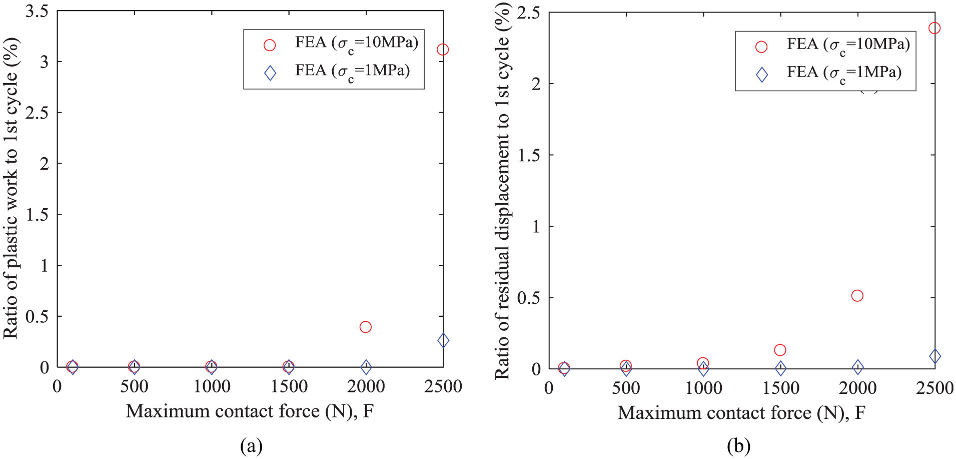
(a) Ratio of plastic work and (b) residual displacement to those of the first cycle separately versus cycle number for monodecreasing loading.
The results of monodecreasing loading can be extended to a more general situation because of the elastic shakedown properties. If the initial loading level is higher than the subsequent loading level, no matter monodecreasing or not, the reloading process can be approximately simplified as elastic behavior, that is, the extended monodecreasing loading.
Monotonically increasing loading
The monotonically increasing loading process with maximum load from 100 to 3000 N is shown in Figure 15. Due to the effect of residual plastic deformation of the previous loading, the consecutive loading curve is hardened, and the stiffness of the virtual nonlinear spring is strengthened, comparing with the single load of the same level of maximum load. Also, the residual displacement of each cycle is a little bit larger than single load, while the plastic work caused by each cycle is obviously lower than single load in our example (see Figure 16(a) and (b)). It should be noticed that the plastic deformation continuously expands with the subsequent loading, and no shakedown behavior is expected for mono-increased loading process.

(a) Contact force versus displacement for mono-increased loading for σc = 10 MPa and (b) time history of loading.

(a) Normalized residual displacement and (b) normalized plastic work versus normalized displacement for σc = 10 MPa.
Seismic loading
The seismic action is cyclic or repeated loading essentially and can be decomposed as the superposition of single loading–unloading process without considering the difference between transient process and steady state, so it is meaningful to examine the relationship among the natural dynamic actions and those three types of idealized loading histories above. With the absolute values of maximum amplitude being scaled to the same value (i.e. 3 m/s 2 ), the acceleration time histories of three famous earthquake records are shown in Figure 17(a)–(c). The three earthquake events referred are El Centro earthquake with 6.9 Mw occurred on 18 May 1940, Kobe earthquake (Great Hanshin earthquake) with 6.9 Mw happened on 17 January 1995, and Wenchuan earthquake with 7.9 Mw took place on 12 May 2008. With regard to the wave shape, the maximum acceleration amplitude of both El Centro earthquake and Kobe earthquake occurs quickly after the first arrival of P waves (less than 7% and 19% of the whole time recorded, respectively), so the effect of seismic action before the maximum amplitude is small and thus they can be represented as the extended monodecreasing loading process mentioned above. As for the Wenchuan earthquake, the maximum absolute value of acceleration happens a little later (about 25% of the whole time recorded), which shows the limited hardening effect as repeated loading or monoincreasing loading. Moreover, because of the elastic shakedown properties of monotonically decreasing loading mentioned above, the unloading and reloading models presented are also effective for the action of aftershocks, which are not negligible for their magnitude and amount.

Seismograms of (a) El Centro earthquake, (b) Kobe earthquake, and (c) Wenchuan earthquake (the time of maximum amplitude is marked by dashed line).
Conclusion
The loading, unloading, and reloading behavior of spherical contact for elastic–plastic geomaterial has been analyzed by FEA calculations. The influence of material properties and loading history on the unloading and reloading responses has been examined. Based on numerical results and theoretical analysis, the main conclusions can be drawn as follows:
Hysteretic phenomena (represented by residual displacement and plastic work) decrease quickly after the first cycle, and the subsequent cycles will step into elastic shakedown state eventually, thus the hysteretic effect of subsequent cycles can be omitted reasonably.
A critical number of cycles can be used to estimate the state of ratchetting, plastic shakedown as well as elastic shakedown when repeated loadings are high.
The subsequent curves will be stiffer than the previous ones, especially when the yield strength is high and ratchetting effect is not strong.
This model presented can be extended to describe the deformation behavior of spheres under earthquake as well as aftershocks by considering the impact effect.
Footnotes
Handling Editor: Shun-Peng Zhu
Declaration of conflicting interests
The author(s) declared no potential conflicts of interest with respect to the research, authorship, and/or publication of this article.
Funding
The author(s) disclosed receipt of the following financial support for the research, authorship, and/or publication of this article: This study received financial support from the National Natural Science Foundation of China (NSFC: 51308474) and the Fundamental Research Funds for the Central Universities (No. 2682017CX005).