
Abstract
Combined with two approaches of sliding mode control and backstepping control, an adaptive sliding mode–based backstepping control scenario on the basis of nonlinear disturbance observer is proposed to complete maximum torque per ampere control for permanent magnet–assisted synchronous reluctance motor. The constraint relation of permanent magnet–assisted synchronous reluctance motor under maximum torque per ampere control is built, and the design of the controller is elaborated in detail. The uncertainties of modeling errors considering unmatched items are estimated through a presented nonlinear disturbance observer. The adaptive law reflecting the modeling error of the system is constructed. Globally asymptotic stability and convergence of the tracking error for the system are validated through Lyapunov stability criterion. Simulation and experimental results illustrate that external disturbances and uncertainties are observed correctly by nonlinear disturbance observer; the close-loop system controlled by the proposed controller can track the references rapidly and precisely, and the designed controller has a good robust ability.
Keywords
Introduction
In the past decades, direct current (DC) motor drive has been gradually replaced by alternating current (AC) motor drive. Nowadays, AC motor drive occupies a dominant position in a large amount of speed control applications. There into, squirrel cage induction motors have been extensively used in many AC drive systems due to its low cost and simple structure. However, its inherently low efficiency and difficult to control makes the utilization of induction motor in high-precision control field not so ideal. With the popularization of permanent magnet materials, permanent magnet synchronous motor (PMSM) catches the attention of the public with its high efficiency, simple structure, and high torque–inertia ratio. Nevertheless, high cost of magnetic materials and sensitivity of magnetic materials to temperature are hindering wide application of such motor to a certain extent. In addition, synchronous reluctance motor (SRM) developed in early times has almost been ignored by current researchers in AC motor drives. One of the great advantages for this type of motor is that through designing its d axis and q axis reactance ratio reasonably, which is also called as changing the saliency ratio, it can achieve speed control of high efficiency and acquire high torque and wide constant power. Therefore, an appealing point is to combine PMSM with SRM to develop a new type of motor, which is permanent magnet–assisted synchronous reluctance motor (PMa-SynRM).
As a combination of two kinds of motors, PMa-SynRM possesses many special advantages of broad speed range of flux-weakening control, good inverter utilization, high efficiency, and natural synchronization, which receive more and more attentions. Due to vital importance of saliency ratio for PMa-SynRM, current research primarily concentrates on optimizing motor body and designing new motor structure. Lohninger et al. 1 propose to use ferrite magnets to reduce manufacturing cost, and they also points out that the placement of magnets in stator is only to enhance the torque efficiency. Niazi et al. 2 designed an innovative motor structure with permanent magnets laid up in rotor core to acquire low-cost and high average electromagnetic torque. For achieving extensive constant-power operation and reducing torque ripple, d axis flux linkage is designed to approach to zero, and the size of permanent magnet is altered by Kim et al. 3
Moreover, the control technology for PMa-SynRM is an issue of great significance but researched relatively inadequately. Due to strict synchronization requirement of speed and power frequency for synchronous motor, its speed adjustment is achieved through variable voltage and variable frequency. There are three frequently used control methods: U/f control, direct torque control (DTC), and vector control (VC). As a scalar control method, U/f control is easy to implement and has a low cost. However, poor dynamic performance, slow torque response, and low motor torque utilization restrict its promotion. 4 On the basis of torque and flux errors between reference values and observed values, DTC manages switching states of inverter directly through real-time feedback control. Therefore, the merit of DTC is responding to the input commands rapidly. But large on-line computations lead to a certain delay, and impulse current and torque ripple worsen control performance during startup and load variation. 5 VC is known as high-accuracy, high-dynamic performance, and strong speed stability. 6 For VC, in comparison with id = 0 control, maximum torque per ampere (MTPA) enables PMa-SynRM to output a larger low-speed torque and reduces the capacity of inverter.
Actually, in contrast with conventional PMSM, one of the specific features for PMa-SynRM is that its reluctance torque is supplemented by a permanent magnet torque, which increases its output torque and improves power factor. For sufficient utilization of the two torques, MTPA control is favorable for motor operation, which is a hot spot indeed and state-of-the-art technology.7,8 The key of MTPA control is to distribute d axis and q axis currents reasonably. Due to complicated nonlinear relationship between d axis and q axis currents, look-up table method is frequently introduced to improve the real-time ability. 9 Acquiring reference currents through off-line look-up table method is convenient for engineering application, but it requires massive storage space, and partly off-line look-up table method is proposed. 10 Anyways, look-up table method increases the workload of off-line test and is inevitably to occupy some storage space. Hence, some improved algorithms are applied in this area. Finite element method (FEM) as a popular method is used to optimize the currents 11 and considers the effect of saturation. 12 For various types of PMa-SynRM, optimization control through FEM needs considerably complex modeling and analysis in spite of simpleness and effectiveness. 13 Furthermore, due to the parameters of PMa-SynRM such as stator resistance, flux linkage vary with temperature. 14 Niazi et al. 15 proposes a parameter estimation based robust MTPA control strategy via the technology of multiple reference frame, and sliding mode control (SMC) is utilized to construct robust MTPA controller by Chakali et al. 16 and Foo and Rahman. 17
Backstepping control (BC) is a novel and valid control approach suitable for nonlinear system.18–20 Through introducing virtual controllers and back-step design, an initial high-dimension system is converted into multiple low-dimension subsystems. For MTPA, BC is successfully applied to regulate the speed of PMSM.21,22 However, the main defect of conventional BC method is that the regression matrices increase the complexity of control under the assumption of linear parameters. 23 The accurate computation of derivatives in virtual variables may also induce “calculation expansion” or “calculation explosion,” and the singularity and over-parameterization are difficult to avoid. So some improved approaches combining of BC and other design methods are put forward.24,25 SMC is an approach with the merits of simpleness, robustness, and reliability, and is particularly suitable for controlling the uncertain system. For an uncertain system with external disturbances, SMC can guarantee the robustness of the whole system. 26 But the presence of chattering limits its application. Combination of BC with SMC can simplify the design of controller, avoid the defect of computation explosion in conventional BC and inhibit the mismatching uncertainties. An algorithm composited with adaptive variable structure control and BC is proposed by Song et al. 27 The variable structure based BC has no sliding mode. So it does not solve the problem of calculation explosion, and its realization is relatively difficult. A careful design guidance laws integrated with SMC and fuzzy methods are illustrated by Chen et al. 28 In reality, the construction of a fuzzy logic system greatly depends on expert knowledge, and the updating of the weights requires spending a lot of learning time. The technology of nonlinear disturbance observer (NDO) enables to eliminate the uncertainties of external disturbances and unmodeled dynamics and is used in many actual systems.29,30 An adaptive backstepping-based MTPA control of PMa-SynRM is proposed to deal with fully uncertain parameters in Yu et al. 31 Adaptive laws are established to determine these uncertain parameters. As mentioned above, a certain amount of computations are a challenging issue in implementation. The main contribution of the article, as an extension of Niazi and Toliyat, 32 is to relax the adaptive laws reflecting the uncertainties of fully parameters and reduce the computation. Meanwhile, the uncertainties of fully parameters by Yu et al. 31 are extended to a composite unknown uncertainties including modeling errors, parameter variations and external disturbances in this article. As in addition to Yu et al., 31 employment of BC into PMa-SynRM is seldom found to the extent of our knowledge. In allusion to MTPA control of PMa-SynRM below base speed and considering model parameter uncertainties and external disturbances with mismatching items, a composite NDO-based adaptive SMC BC algorithm is proposed by integrating the theories of adaptive BC and SMC. Simultaneously, NDO is designed to compensate for the effects acted by parameter uncertainties and external disturbances. The adaptive law designed in controller construction process furthermore fullfils the estimation of uncertainties and enables the designed controller to rid of the uncertainties’ dependence of unknown upper bound.
The remaining of the article is organized as follows. The constraint relation of PMa-SynRM under MTPA control principle for PMa-SynRM is presented in section “Constraint relation of currents in PMa-SynRM under MTPA control principle.” In section “Adaptive SMC-based backstepping controller design,” an adaptive SMC backstepping controller design based on NDO is proposed, and the stability of the control scheme is testified through Laypunov stability criterion. Section “Experiment and analysis” conducts the simulations and hardware experiments to validate the effectiveness and accuracy of the proposed algorithm. Ultimately, the conclusions are summarized in section “Conclusion.”
Constraint relation of currents in PMa-SynRM under MTPA control principle
In d–q axis synchronous rotating coordinate system, the mathematical model of PMa-SynRM with permanent magnets in q axis can be described as 32

where θr and ωr are the mechanical rotor angle and speed, respectively. Jm is the moment of inertia, Bm is the viscous damping coefficient, Te is the electromagnetic torque, TL is the load torque, id and iq are the d axis and q axis stator currents, ud and uq are the d axis and q axis stator voltages, Ld and Lq are the d axis and q axis inductances, Rs is the stator resistance, np is the number of pole pairs, and ψf is the flux linkage produced by permanent magnets. Fω, Fd, and Fq depict unknown uncertainties indicating modeling errors in ωr, id and iq, respectively.
The electromagnetic torque Te can be written as

Utilization of MTPA control is expected to obtain maximum electromagnetic torque through stator current as low as possible, which can be converted into a solution of extreme problem given by
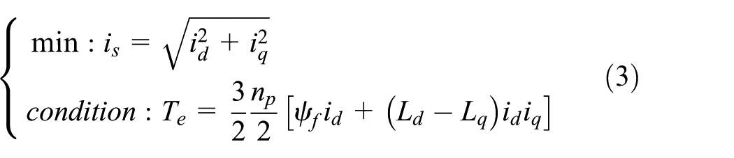
where is is the stator current.
Through introduction of a Lagrangian multiplier λ, the auxiliary function is constructed as

Using partial derivatives of id, iq, and λ in equation (4), respectively, we can obtain

Let every function in equation (5) equal to zero, the relationship of d–q axis currents in MTPA control can be gained as

Equation (6) indicates that if id is known, q axis reference current iqref can be determined.
Adaptive SMC-based backstepping controller design
NDO design
System (1) is rewritten as the form of state space

where
Let

where
NDO is designed as

where

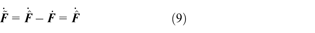
By substituting equation (10) into equation (11), we can obtain
Equation (12) implies that if a suitable

where t is the time,
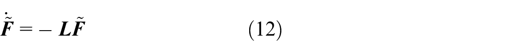
Let

Equation (14) shows that the uncertainties are decreased by NDO. System (7) can be changed into

where
Proposed adaptive control
In terms of BC principle, the error variables eω, ed, and eq are defined as

where

Let
Then, idref can be chosen as
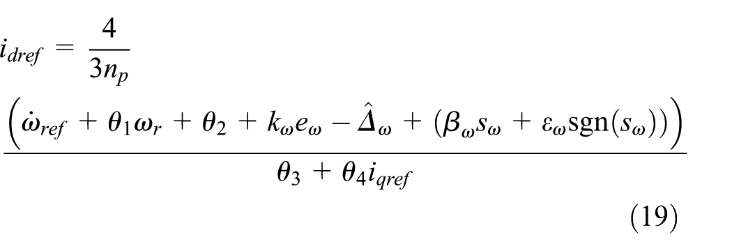
where
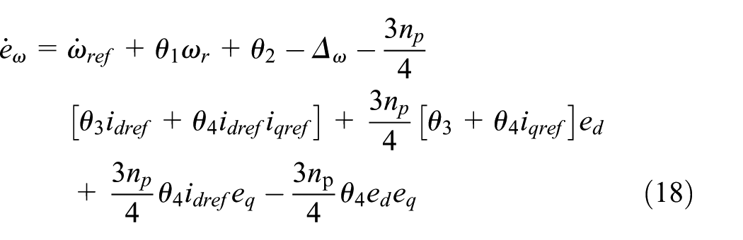
By substituting equation (19) into equation (18)
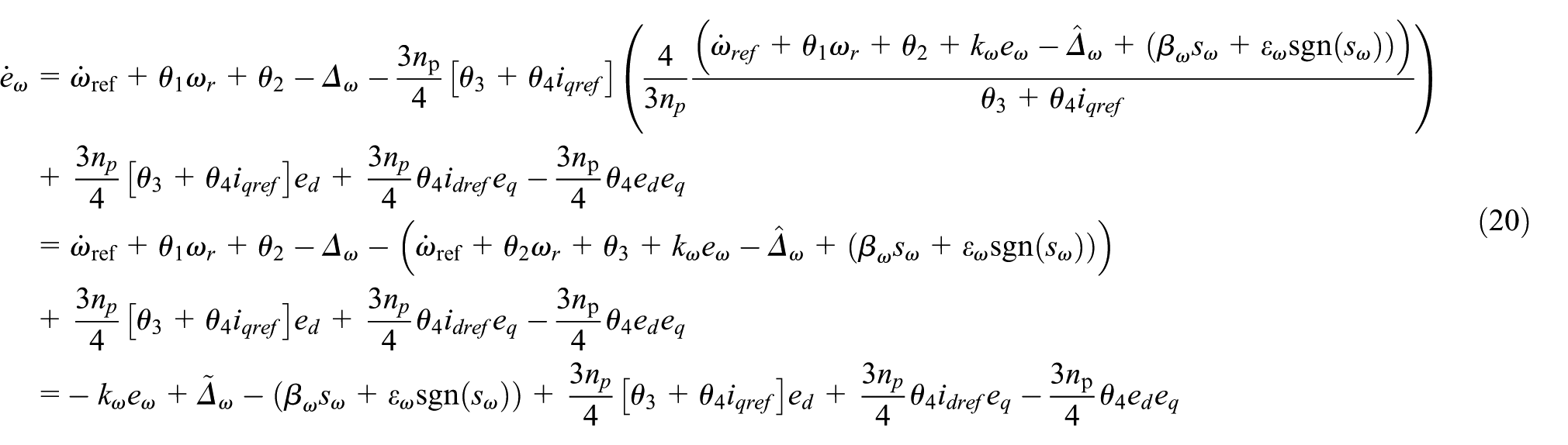
where

By derivative of equation (19)

Let

The control input usd can be chosen as

where
By substituting equation (24) into equation (23)

where

By derivative of equation (6)

Let

The control input usq can be selected as

where
By substituting equation (29) into equation (28)

where
To utilize the controller usd and usq described in equations (24) and (29), respectively, the upper bound of

By derivative of V1
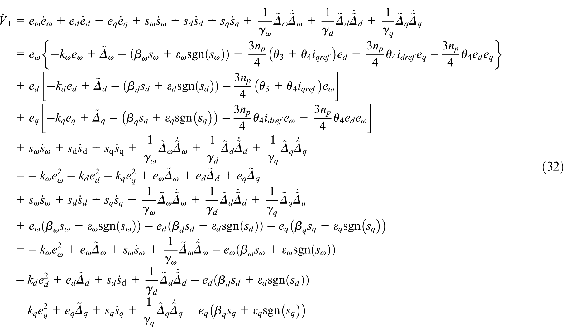
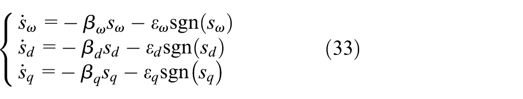
The adaptive law of SMC is chosen as
The adaptive law of

By substituting equations (33) and (34) into equation (32)

Equation (35) indicates that Laypunov function is negative definition and the system is globally asymptotic stable. Hence, the system errors shown in equation (16) can converge to zero in a finite time. For elimination of the chattering problem in designed controller, signum function sgn in equations (24) and (29) are replaced by saturation function sat. The ultimate MTPA controller based on adaptive SMC backstepping is shown in equation (36) with NDO in equation (10) and adaptive law in equation (34)

Moreover, it is necessary to consider real limitation on domain of control signal in design phase. For PMa-SynRM, the outputs of speed loop and current loop cannot be arbitraryly large. Due to the output of the speed is the reference of d axis current idref, the current cannot exceed the limit of the motor. In other words, there are upper and lower limits for the output of speed loop. It supposes that the upper and lower limits for the motor are ilim+ and ilim– individually. The anti-windup approach is used after the output of speed loop, which is described as

The control schematic diagram is shown in Figure 1. The control problem in the article can be described as: for a PMa-SynRM with comprehensive interferences produced by the uncertainties of modeling errors, NDO in equation (10) is designed to estimate the comprehensive interferences; speed backstepping controller in equation (19), and current backstepping controller in equation (36) are proposed based on MTPA control in equation (6) and adaptive law in equation (34) to regulate the speed and d–q axis currents to track respective references rapidly.
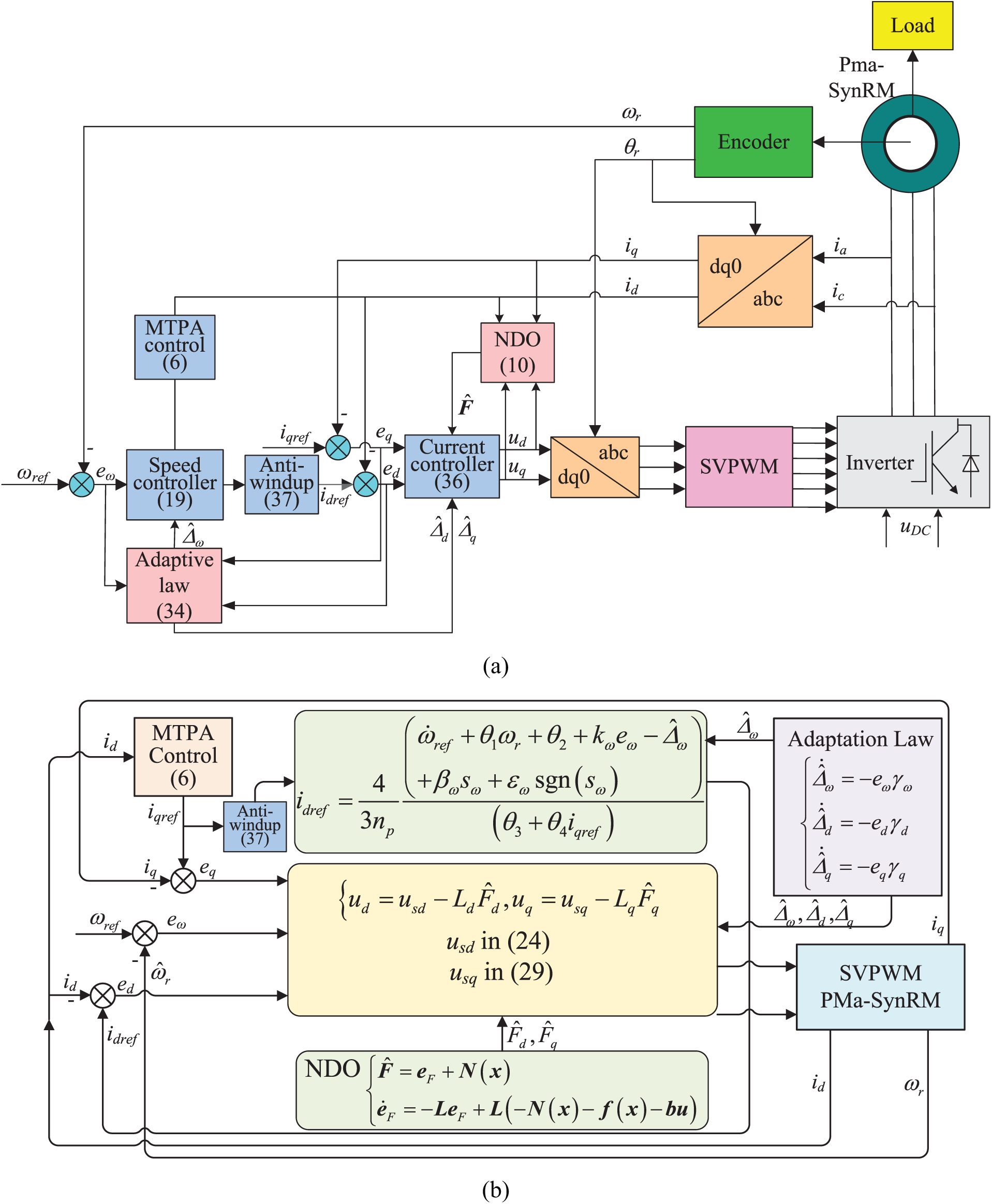
The schematic diagram of the proposed control scheme: (a) the overall configuration diagram and (b) the concrete nonlinear backstepping controller.
Selection of controller parameters through differential evolution algorithm
According to equations (24), (29), (33), and (34), there are 13 parameters that should be chosen in the controller, which are kω, kd, kq, βω, βd, βq, εω, εd, εq, γω, γd, γq, and
The design procedure of the parameter optimization is displayed as follows:
Step 1: Initialization of the population. For a population in the study, the individual is defined as x =[kω, kd, kq, βω, βd, βq, εω, εd, εq, γω, γd, γq,
Step 2: Determination of fitness function. The target of fitness function is to guarantee the control variables to track the references and reduce the estimation errors. The fitness function is shown as

where k1, k2, k3, k4, k5, and k6 are the adaptive constants and selected as 0.5, 0.1, 0.1, 0.1, 0.1, and 0.1, respectively.
Step 3: Updating the vectors of mutation and trial. The mutation vector


where r1, r2, and r3 are the random numbers and are not the same with each other, and the running index i, Fi, G , and CRi, G are the scale factor and cross-over factor, Fi,1 and CRi,1 are randomly determined from [0.1, 0.9] and [0, 1] at the start, r(j) is a random number between 0 and 1, and rn(i) is a random integer between 1 and D.
Step 4: Updating the factors Fi,G and CRi,G

where randi indicates a random number.
Step 5: Updating the population xi,G+1

Experiment and analysis
Digital simulation
In this section, digital simulations are conducted in MATLAB to demonstrate the correctness and effectiveness of the proposed algorithm. The parameters of the system are shown as: stator resistance Rs = 3.16 Ω, d axis inductance Ld = 0.139 H, q axis inductance Lq = 0.062 H, flux linkage of permanent magnet ψf = 0.47 Wb, number of pole pairs np = 10, viscous damping coefficient Bm = 0.0005 N/rad/s, and moment of inertia Jm = 0.06 kg m 2 .
The simulation time is 60 s and the sampling time is 0.001 s. For testing the performance of the proposed algorithm, the reference of speed is set as dynamic variation: startup to a low speed of 10 r/min with a increasing step to 300 r/min at t = 10 s; then continuous operation to t = 50 s with a decreasing step to 10 r/min. Furthermore, load torque is also changing with the time: from startup to 20 s, the load torque is 1.5 N m; at t = 20 s a 3 N m increased instruction is injected and lasting 20 s; then load torque returns to 1.5 N m at t = 40 s. For displaying the superiority of the approach, NDO-based BC control with no SMC and NDO-based PI control are also completed, which are denoted as NDO-BC and NDO-PI, respectively. The control parameters determined through DE optimization algorithm method are shown as: kω = 50.82, kd = 500.12, kq = 1500.04, βω = 100.52, βd = 300.23, βq = 400.01, εω = 20.47, εd = 11.05, εq = 25.68, γω = 0.60, γd = 1.82, γq = 2.58, and
The digital simulation results are displayed in Figures 2 and 3, where the simulation results of the three algorithms are compared in Figure 2. Figure 2(a) illustrates the speed result, for the proposed algorithm in the article, they have no apparent fluctuations in the whole time, especially in speed reference variations at t = 10 and 50 s. However, the other algorithms of NDO-BC and NDO-PI have larger fluctuations when changing the speed references. Moreover, the changing of load torque at t = 20 and 40 s leads to larger overshoots for NDO-BC and NDO-PI, and the proposed algorithm experiences a smooth transition more or less. Figure 2(b) and (c) shows the results of id and iq, respectively. There have almost no oscillations in current waveforms for the proposed algorithm at startup and at the time of changing reference in contrast with the other two approaches, which indicates that the proposed scheme ensures the state variables of the system to follow the references more quickly. Also, the integral of absolute error (IAE) is provided as an index for numerical metric. The values of IAE in Figure 2(a) for the three algorithms are 918.6 (NDO-BC + SMC), 1260.4 (NDO-BC), and 2425.8 (NDO-PI), respectively. For id in Figure 2(b), the values of IAE are 548.9 (NDO-BC + SMC), 886.3 (NDO-BC), and 1225.5 (NDO-PI) individually; and the values of IAE for iq in Figure 2(c) are 410.0 (NDO-BC + SMC), 741.1 (NDO-BC), and 1212.0 (NDO-PI), respectively. Figure 3(a)–(c) demonstrates the observation results of Fω, Fd, and Fq, respectively, which displays that the designed NDO can basically observe the disturbances and uncertainties rapidly and accurately.

Comparative simulation results of ωr, id and iq with three control approaches: (a) ωr, (b) id, and (c) iq.

Observation results of Fω, Fd, and Fq: (a) Fω, (b) Fd, and (c) Fq.
Hardware test
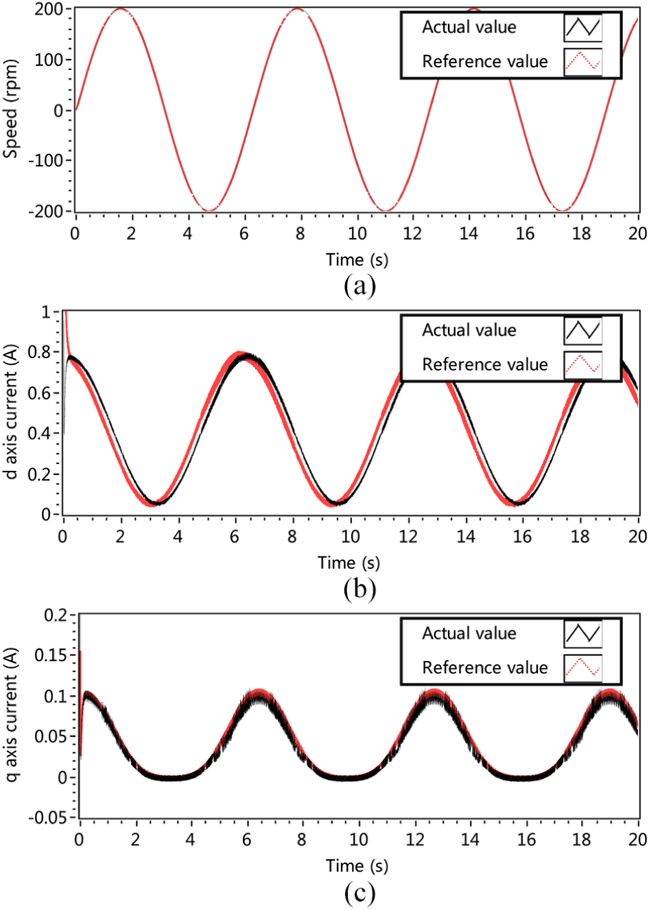
For validating the effectiveness of the proposed algorithm better, two hardware experiments with different dynamic reference speeds are implemented. The parameters in hardware test are the same as the digital simulation. First, the reference speed is set to 200 × sin(t) r/min. The experimental results are shown in Figure 4. Figure 4(a) plots the tracking of the reference speed. The speed regulated by the algorithm follows with the speed signal very well. Figure 4(b) and (c) shows the plots of d axis and q axis currents individually. Along with the changing of sinusoidal speed waveform, d axis and q axis currents demonstrate the sinusoidal waveforms similarly. Furthermore, the output d axis and q axis currents have basically completed the tracking of their actual commands, respectively. Second, the reference speed is set to the triangular waveform. The detail of the triangular waveform is shown in Figure 5(a). Controlled by the proposed algorithm, the speed of the motor shown in Figure 5(a) tracks the triangular reference speed very well. Followed with the triangular speed command, the output currents of d axis and q axis are shown in Figure 5(b) and (c). The currents also represent the characteristic of ramp waveforms. Similarly, the currents track their references well.
Experimental results of speed, d axis current and q axis current with sinusoidal speed reference: (a) speed, (b) d axis current, and (c) q axis current.
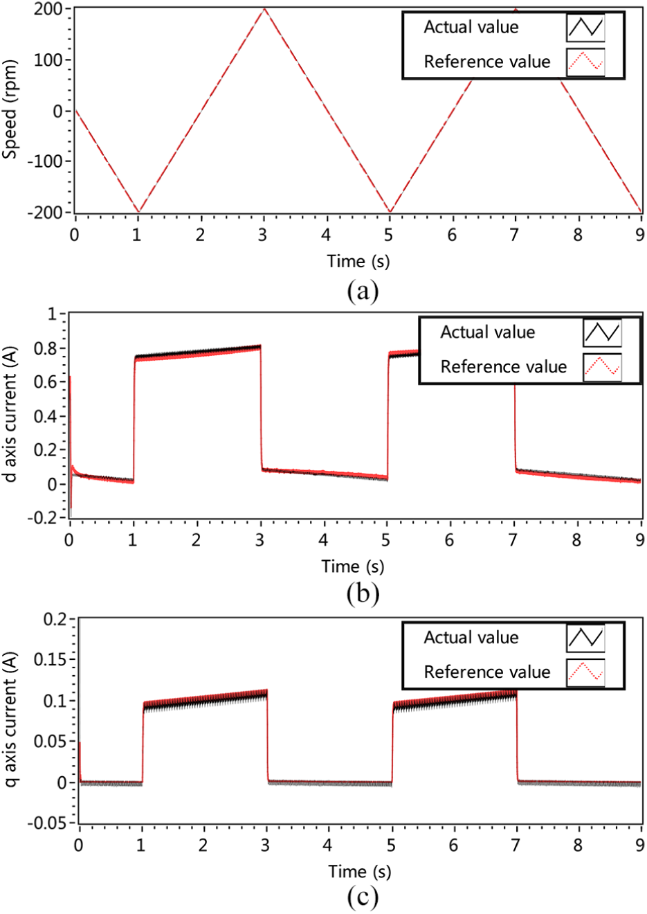
Experimental results of speed, d axis current and q axis current with triangular speed reference: (a) speed, (b) d axis current, and (c) q axis current.
Conclusion
An adaptive sliding mode–based BC algorithm is proposed for MTPA control of PMa-SynRM. An NDO is designed to estimate the uncertainties of modeling errors. In addition, an adaptive law is devised to further compensate for the disturbances and uncertainties. The theoretical analysis and experimental results show the advantages of the algorithm as follows: (1) the proposed approach guarantees globally asymptotic stability of the close-loop system and enables the system to track the reference signals correctly and quickly. (2) The designed NDO can estimate the disturbances and uncertainties precisely, and it is beneficial to reduce the chattering and improve the control performance. (3) Due to the existence of adaptive law, SMC-based BC is independent of uncertainties upper bound of disturbances.
Footnotes
Handling Editor: Jose Ramon Serrano
Declaration of conflicting interests
The author(s) declared no potential conflicts of interest with respect to the research, authorship, and/or publication of this article.
Funding
The author(s) disclosed receipt of the following financial support for the research, authorship, and/or publication of this article: This work was partially supported by the National Natural Science Foundation of China (grant no.: 51407077), the Fundamental Research Funds for the Central Universities of China (grants no.: 2016XS96 and 2017MS095), and the Science and Technology Project of State Grid Corporation of China Headquarter (grant no.: 5204BB16000 F).