
Abstract
This article focuses on static output feedback
Keywords
Introduction
It is well known that suspension system is one of the important parts of vehicle chassis, which heavily affects the handling stability and ride performance which are at odds with each other. 1 Due to structural constraints, the passive suspension system can hardly improve the two properties at the same time. However, the active suspension system can synchronously give consideration to the two conflicting performances through adjusting the parameters of suspension system proactively according to the state of vehicle movement and the condition of road surface, rather than passive suspension whose parameters are fixed and designed by a compromise. 2 At present, active suspension system is faced with parameter uncertainty of system, 3 input delay of actuator, input disturbance of uneven pavement, and measurement output disturbance of sensor,4,5 which have great influences on the stability and control effect of active suspension system.1,2,6
Therefore, in the recent decades, the control models and strategies of active suspension system are attracting more and more attention and exploration. A single-step method to acquire static output feedback controller for vehicle active suspension system was proposed based on finite frequency.
7
A two-step computational approach was used for the design of static output feedback controller for vehicle suspension system.
8
A kind of dynamic output feedback
However, most of the existing related literatures are concerned with one or two problems of parameter uncertainty of system, input delay of actuator, input disturbance of uneven road, and measurement output disturbance of sensor.
25
The design issues of active suspension controller are rarely involved with a comprehensive consideration of the above four factors, especially for static output feedback
Based on
According to the designed controller and the specific vehicle parameters, the simulation model of quarter-vehicle active suspension system is established, and the simulations of three cases are exploited to demonstrate the feasibility and effectiveness of the proposed schemes.
This article will be organized as follows. In section “Problem formulation,” the typical structure and mathematical model of a quarter-vehicle active suspension system are provided, and the state-space equation of system is established. In section “Main results,” the static output feedback
Problem formulation
The typical structure and model of quarter-vehicle active suspension system with 2 degrees of freedom are shown in Figure 1, in which

Structure and model of active suspension system: (a) typical structure of active suspension system and (b) quarter-vehicle suspension model.
Based on Figure 1 and Newton’s second law, the dynamics differential equations of quarter-vehicle active suspension system can be established as follows

where

where
According to the structural characteristics and performance requirements of active suspension system, the suspension deflection
Considering the input delay of actuator, the parameter uncertainty of system, the input disturbance of road, and the output disturbance of measurement, according to equation (1), the quarter-vehicle active suspension system can be described by the following state-space equations
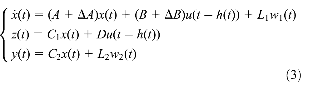
where

where
Let

where
Main results
In this section, the problem of static output feedback
Theorem 1
Consider the quarter-vehicle active suspension system (3) without disturbances, that is,

where

is asymptotically stable, that is, the control output also approaches to zero, where
Proof
Define
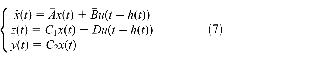
According to equation (7) and

Considering the Lyapunov–Krasovskii function as follows
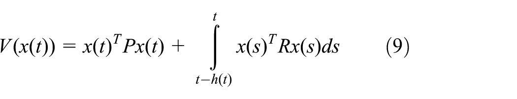
where
From equations (8) and (9), we can obtain the derivative of

The above formula (10) can be changed as

where
According to equation (4),

It can be known from Lemma 1 that there exists a scalar

According to equations (2), (11), and (13), it can be obtained that
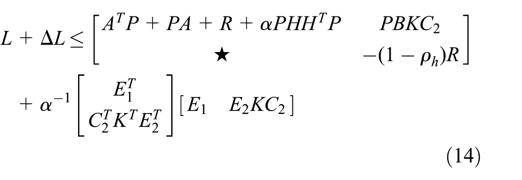
Let

According to the Schur-complement theorem (Lemma 2), equation (15) is equivalent to the following inequality

Through equations (14) and (16), it is easy to get that

Therefore,
Theorem 2
Consider the quarter-vehicle active suspension system (3) with disturbances, if there exist positive-definite matrices
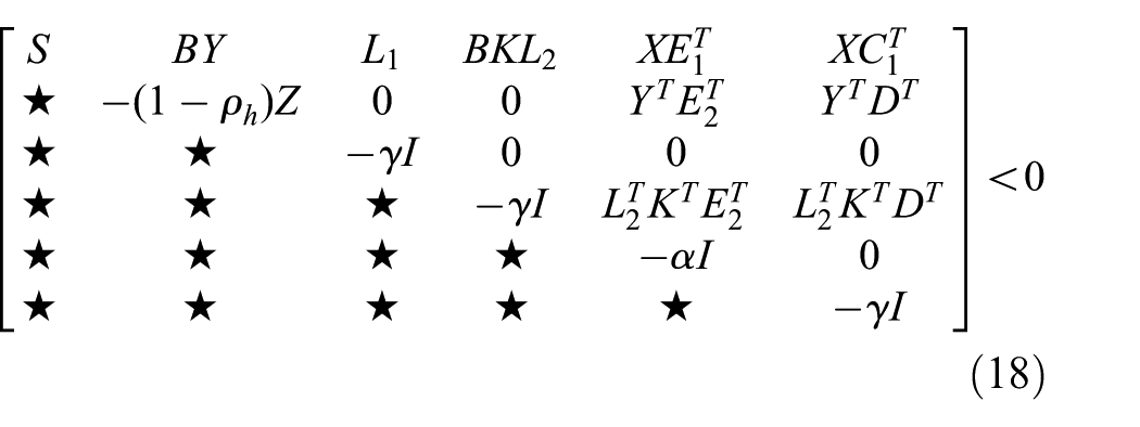
where

is asymptotically stable for
Proof
Similar to Theorem 1, define

According to equation (20) and

Consider the Lyapunov–Krasovskii function as follows

where
From equations (21) and (22), we can obtain the derivative of
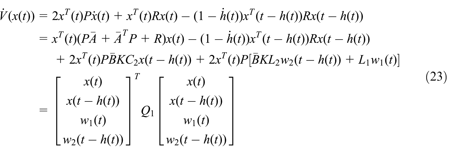
where

According to equation (4),

It can be known from Lemma 1 that there exists a scalar

Define
where
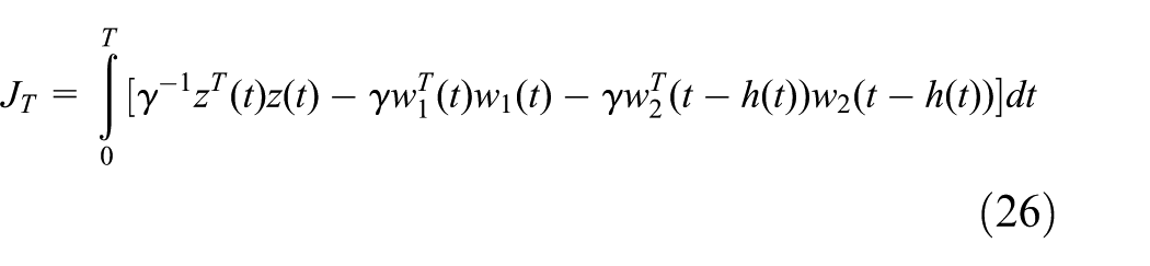
For the arbitrary nonzero perturbations and

From equation (20),

Then
where
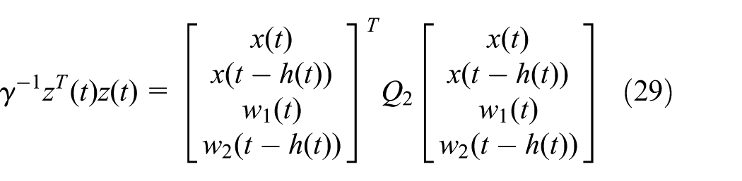
Simultaneously,

where
Therefore, equation (27) can be expressed as
Let

According to the Schur-complement theorem (Lemma 2), equation (32) is equivalent to the following inequality

where

Define
Through equations (23), (25), (29), (30), and (34), it is easy to find

Therefore, it can be known from equation (31):

The designed controller
Numerical simulation
In this section, two numerical examples are presented to demonstrate the feasibility and effectiveness of the proposed schemes. The selected model parameters of quarter-vehicle active suspension system are shown as
Simulation without disturbances
According to equation (7), the control block diagram of active suspension system without disturbances is expressed as Figure 2.

Block diagram of control system without disturbances.
Based on MATLAB/Simulink software, the simulation model of quarter-vehicle active suspension system without disturbances is established as Figure 3.
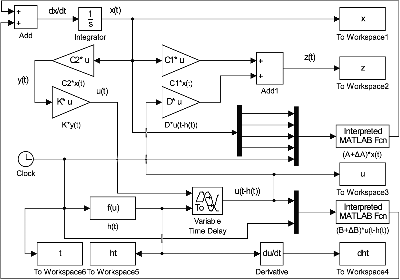
Simulation model of control system without disturbances.
The initial value of system simulation is set as

where

Input delay signals of control system: (a) function of input delay and (b) derivative of input delay.
The simulation time is set to 20 s, then the control output signals of system without disturbances, for example, acceleration of sprung mass, speed of sprung mass, suspension deflection, and tire deflection, can be easily obtained as Figure 5, and the control input signal of active suspension system with input delay can also be easily gained as Figure 6.

Control output signals of system without disturbances: (a) acceleration of sprung mass, (b) speed of sprung mass, (c) suspension deflection, and (d) tire deflection.
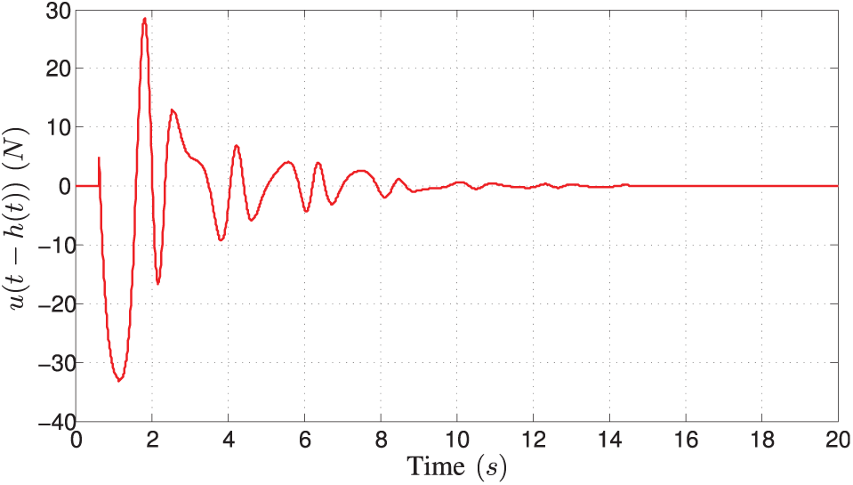
Control input of active suspension system with input delay.
From Figure 5, it can be seen that the acceleration of sprung mass, speed of sprung mass, suspension deflection, and tire deflection of active suspension system with input delay and parameter uncertainty are asymptotically stable, and the designed static output feedback
Simulation with disturbances
According to equation (3), the control block diagram of active suspension system with the input disturbance of road and the output disturbance of measurement is expressed as Figure 7.

Block diagram of control system with
Based on MATLAB/Simulink software, the simulation model of quarter-vehicle active suspension system with

Simulation model of control system with
Simulation with input disturbance of road
In order to exhibit the effectiveness of the proposed static output feedback

where

Input disturbance of an isolated bump.
Let
The simulation time is also set to 20 s, then the time response comparison of control output signals to the above bump disturbance between passive suspension and active suspension can be obtained as Figure 10, and the control input signal of active suspension system can be gained as Figure 11.
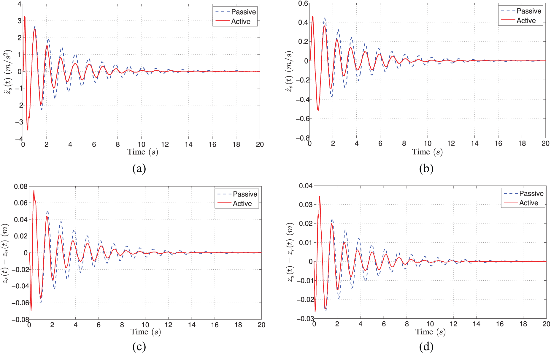
Time response comparison to bump disturbance between passive suspension and active suspension: (a) acceleration of sprung mass, (b) speed of sprung mass, (c) suspension deflection, and (d) tire deflection.

Control input of active suspension system with bump disturbance.
From Figure 10, it is obvious that the acceleration of sprung mass, speed of sprung mass, suspension deflection, and tire deflection of active suspension system attenuate faster than those of passive suspension system, which shows the designed static output feedback
Simulation with input disturbance and output disturbance
In order to exhibit the effectiveness of the proposed static output feedback

Output disturbances of measurement.
The time response comparison of control output signals of active suspension can be obtained as Figure 13, between only with input disturbance of road and both input disturbance and output disturbance. From Figure 13, it can be seen that the designed static output feedback
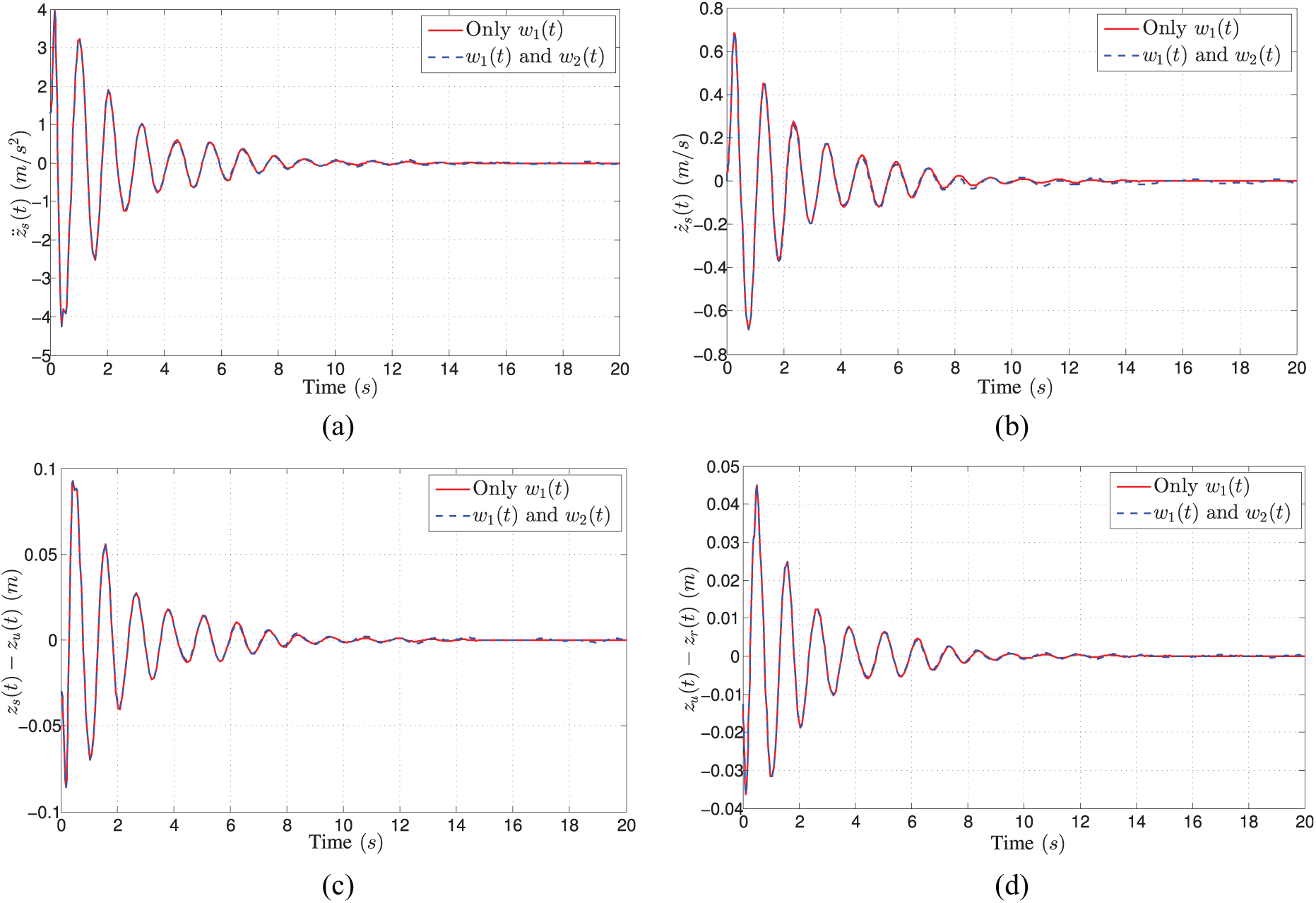
Time response comparison to different disturbances of active suspension: (a) acceleration of sprung mass, (b) speed of sprung mass, (c) suspension deflection, and (d) tire deflection.
The comparison of control input signals of active suspension can be obtained as Figure 14, between only with input disturbance of road and both input disturbance and output disturbance. From Figure 14, it can be easily seen that the control input signals of the two cases are roughly consistent, which indicates that the designed static output feedback

Control input comparison of active suspension system with different disturbances.
Conclusion
This article has investigated a class of problem about the static output feedback
Footnotes
Appendix 1
Handling Editor: Jan Torgersen
Declaration of conflicting interests
The author(s) declared no potential conflicts of interest with respect to the research, authorship, and/or publication of this article.
Funding
The author(s) disclosed receipt of the following financial support for the research, authorship, and/or publication of this article: This work was jointly supported by the National Natural Science Foundation of China (grant 11705122), the Research Foundation of Department of Education of Sichuan Province (grants 17ZA0271, 16ZA0263, 17ZB0194, and 18ZB0418), the Open Foundation of Enterprise Informatization and Internet of Things Key Laboratory of Sichuan Province (grants 2016WYJ03 and 2017WZY01), the Open Foundation of Artificial Intelligence Key Laboratory of Sichuan Province (grants 2016RYJ04, 2015RYJ03, 2016RYY01, and 2017RYJ01), the Open Foundation of Sichuan Provincial Key Lab of Process Equipment and Control (grant GK201612), the Open Foundation of Material Corrosion and Protection Key Laboratory of Sichuan province (grant 2017CL09), the Innovation Platform & Key Project of International Cooperation of General Institutes of Higher Education of Guangdong Province & Overseas (including Hong Kong, Macao, and Taiwan) (grant 2015KGJHZ025), Research & Innovation Foundation of General University Graduate of Jiangsu Province (grant CXZZ130659), and Natural Science Foundation of Sichuan University of Science & Engineering (grants 2018RCL17, 2018RCL18, 2017RCL10, 2017RCL52, and 2014RC11).