
Abstract
The method of yaw model is used to establish aerodynamic property of heavy truck in computational fluid dynamics and wind tunnel test. A model of multi-body system simulation for heavy truck is built based on design and measure data from body, driving system, steering system, braking system, and powertrain system with TruckSim. Aerodynamic reference point of Society of Automotive Engineers (SAE) and aerodynamic coefficients are as the interface to integrate computational fluid dynamics and multi-body system simulation. A sudden and discontinuous direction change of crosswind is set up in multi-body system simulation, and dynamic performance of the heavy truck is performed by open-loop and closed-loop simulation. Under the given simulation case, lateral offset of the truck for open-loop simulation is 1.55 m and more than that for closed-loop simulation; the roll rate range of both simulations is −1.49°/s to 1.695°/s, the range of lateral acceleration is −0.497 m/s2 to 0.447 m/s2 in open-loop simulation, the range of lateral acceleration is −0.467 m/s2 to 0.434 m/s2 in closed-loop simulation; the range of yaw rate is −1.36°/s to 1.284°/s in open-loop simulation, the range of yaw rate is −0.703°/s to 0.815°/s in closed-loop simulation. The results show that combined simulation of the heavy truck stability can be completed by computational fluid dynamics and multi-body system software under sudden and discontinuous direction change of crosswind.
Keywords
Introduction
With the rapid development of road and highway network, the scale of automotive industry is expanding in the world. When a vehicle is driving on road and highway, it is often affected by crosswind from environment, which is a significant impact on vehicle handling, stability, or safety and may even lead to accidents.
Wind tunnel test and computational fluid dynamics (CFD) simulation are two main methods for investigating aerodynamic characteristics of a vehicle under crosswind. Both wind tunnel test and CFD simulation are applied to see how aerodynamics acts on the vehicle during crosswind condition.
X Liu et al. 1 studied aerodynamic characteristics of various vehicle models with the yaw model method in wind tunnel test. FJ Bello-Millán et al. 2 researched Ahmed’s body drag coefficient for different yaw angles in wind tunnel. Buning and Beauvais, 3 Stewart, 4 and Cairns, 5 respectively, applied the traction model method to gain aerodynamic characteristics in a wind tunnel. Baker 6 and Coleman 7 also, respectively, used the traction model method to study aerodynamic characteristics of truck model in a wind tunnel. Chadwick et al. 8 measured the transient aerodynamic forces and surface pressure of a car with the traction model method in a wind tunnel. Dominy 9 and R Volpe et al. 10 applied the second wind source approach to measure a car’s crosswind characteristics in a wind tunnel.
Dominy and Richardson 11 studied the aerodynamic characteristics of high slide angles in international road rally car with CFD simulation. Tsubokura et al. 12 analyzed the aerodynamic effect of Formula car under unsteady crosswind and proposed that installed vanes created the positive impact on the down-force during cornering in CFD simulation. Albukrek et al. 13 compared unsteady aerodynamic characteristics with CFD simulation and experiment of the airflow on the front wing and tail panels when car turning.
After the aerodynamic characteristics of a vehicle are obtained by wind tunnel test or CFD simulation, an important problem appears on how to apply it to vehicle handling, stability, or safety research. A few scholars established a vehicle model and loaded aerodynamic lateral force at the pressure center position to simulate the handling or stability under steady or transient crosswind.14,15 Yaw rate, lateral acceleration or lateral displacement of the vehicle is characterized to analyze the impact of vehicle handling, stability, or safety under crosswind. These researches are of significance, but aerodynamic forces are loaded in pressure center in these studies.
The shape of a heavy truck is similar to a rectangular solid, and its aspect ratio is large, which makes the truck to be more sensitive to the crosswind effect. The research on heavy truck aerodynamics and dynamics under special conditions such as crosswind can help to enhance heavy truck vehicle performance and make it more perfect.
During driving, a sudden and discontinuous direction change of crosswind will seriously affect the driver’s judgment and even lead to improper operation of the driver, which may cause serious accidents. To investigate the influence of a sudden and discontinuous direction change of crosswind on heavy truck stability, a combined research on aerodynamics and dynamics is presented. In aerodynamics aspect, aerodynamic forces and moments of heavy truck are obtained by CFD simulation, and they are also measured and validated by wind tunnel test in certain range of slide angles. In dynamics aspect, heavy truck is modeled with TruckSim, and the model is verified by dynamic test without crosswind. Aerodynamic reference point of Society of Automotive Engineers (SAE) and aerodynamic coefficients are used to integrate CFD simulation and multi-body system (MBS) dynamics simulation, also to analyze sudden and discontinuous direction change of crosswind effects on dynamic behavior of the heavy truck.
Experiment method and CFD simulation
Method of yaw model
When a vehicle is driving at a constant speed, the air around the vehicle is squeezed and flows along the surface of the vehicle, which results in aerodynamic forces and moments of the vehicle. A driving vehicle under the crosswind is acted by wind from side direction, causing changes of aerodynamic forces and moments of the vehicle.
In order to reproduce practical aerodynamic characteristics of heavy truck under crosswind, aerodynamic characteristics are obtained based on method of yaw model in wind tunnel test and CFD.
The principle of method of yaw model is shown in Figure 1. There is a slide angle between the longitudinal axis of a vehicle and the direction of inlet velocity, the slide angle and inlet velocity are known. In CFD or wind tunnel test, a vehicle is placed in the given slide angle, and air flows on the vehicle at inlet velocity. Inlet velocity


Principle of the method of yaw model.
Different aerodynamic characteristics of heavy truck are established by changing vehicle longitudinal speed
Wind tunnel test
Wind tunnel test is finished at aerodynamics lab of Jilin University. Test section size of wind tunnel is 8 m (length) × 4 m (width) × 2.2 m (height), and it is necessary to use a scaled model of heavy truck in this wind tunnel. The main equipments consist of a 6-component balance measurement system and a turntable system. The 6-component balance measurement system contains a force sensor and a model support device, and the overall error of sensor and data acquisition system reaches 0.05%, which ensures reliability of the measurement results.
The scaled model of heavy truck is 1:7, and its dimensions are: length is 1457.71 mm, width is 358.57 mm, and height is 479.14 mm.
WH Hucho 16 suggests that the critical Reynolds number is not less than 2 × 10⁶. In this research, Reynolds number of the scaled model is 2.22 × 10⁶, and it fits Reynolds number requirement.
Because blockage ratio is 2.04%, there is no blockage ratio correction. In order to avoid interference of the wind tunnel wall, it is required that the frontal area of test model does not exceed 5% of cross-sectional area of test section, and the ratio of front projection width to test section width is less than 30%. For the heavy truck model, the ratio of the frontal area to cross-sectional area of test section is 3.94%, and the ratio of front projection width to test section width is 18.1% within 15° slide angle; therefore, both ratios meet the requirements. When slide angle is less than 15°, the aerodynamic characteristics of heavy truck model could be obtained by both wind tunnel test and CFD simulation at the same time. The validity of CFD simulation results could be obtained by comparing with the wind tunnel test. When slide angle is larger than 15°, both the two ratios do not meet the requirements in wind tunnel test, so all data are obtained by CFD simulation.
The heavy truck model is mounted on the turntable system, as shown in Figure 2. The turntable system is rotated in 0°–15° per 3° interval together with the 6-component balance measurement system. After removing the support device influence in wind tunnel test, six aerodynamic coefficients of heavy truck at a certain slide angle are compared with CFD simulation, respectively.

Wind tunnel and the scaled truck model.
CFD simulation
CFD simulation is completed by STAR-CCM+ of CD-adapco. A large hexahedral cube computational domain is established; six sides of the computational domain are divided into the following four parts: inlet, outlet, wall, and floor. Computational domain length is 180 m, entrance length to vehicle forefront is 48.6 m, computational domain height is 15 m, and computational domain width is 60 m.
Polyhedron and prism boundary layer mesh are used to generate CFD grid. Polyhedron mesh of heavy truck is shown in Figure 3. In order to capture more accurately the turbulent flow in rear of the vehicle, refinement volume in wake area is generated as shown in Figure 4, and other areas are also refined according to the curvature of vehicle structure.
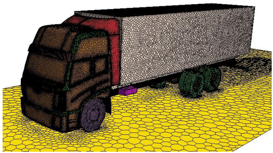
Polyhedral mesh on truck surface.

Spanwise symmetry plane mesh of truck.
Standard
Y+ is considered before the mesh is generated. High y+ (y+ > 30) wall treatment is essential in the classic wall-function approach, where wall shear stress, turbulent production and turbulent dissipation are all derived from equilibrium turbulent boundary layer theory. Low y+ wall treatment is consistent with low-Reynolds number models and assumes that the viscous sublayer is resolved and thus wall laws are not needed. In automotive aerodynamics,
The boundary layer is stretched to the surface of body to obtain a better flow, and it is expanded to eight prism layers as shown in Figure 5. The total cell number is about 8 million.
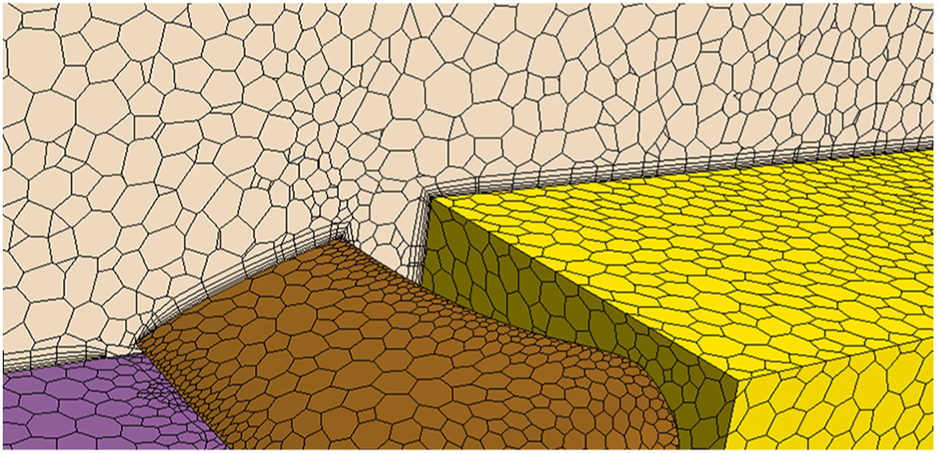
Boundary layer mesh.
The pressure distribution of vehicle body surface not only reflects the flow around a vehicle, but also the aerodynamic forces of the vehicle. The surface pressure distribution of heavy truck is analyzed by CFD simulation in the range of 0°–30° of slide angle, as shown in Figure 6. The pressure changes from −5400 Pa to 1100 Pa, which mainly shows the pressure distribution of the front and right side of the heavy truck. The negative pressure area is mainly the top and right side of cab front, and other most area is the positive pressure area. At 0°, high pressure is mainly concentrated in the front of the cab, while other right side of heavy truck is basically normal atmospheric pressure or slightly higher than the atmospheric pressure, due to the influence of crosswind, the positive pressure area in front of the cab gradually shifts toward the left side of the cab. As the slide angle increases, the offset increases, the area of the positive pressure becomes larger, and thus the result of the corresponding side force increases gradually.
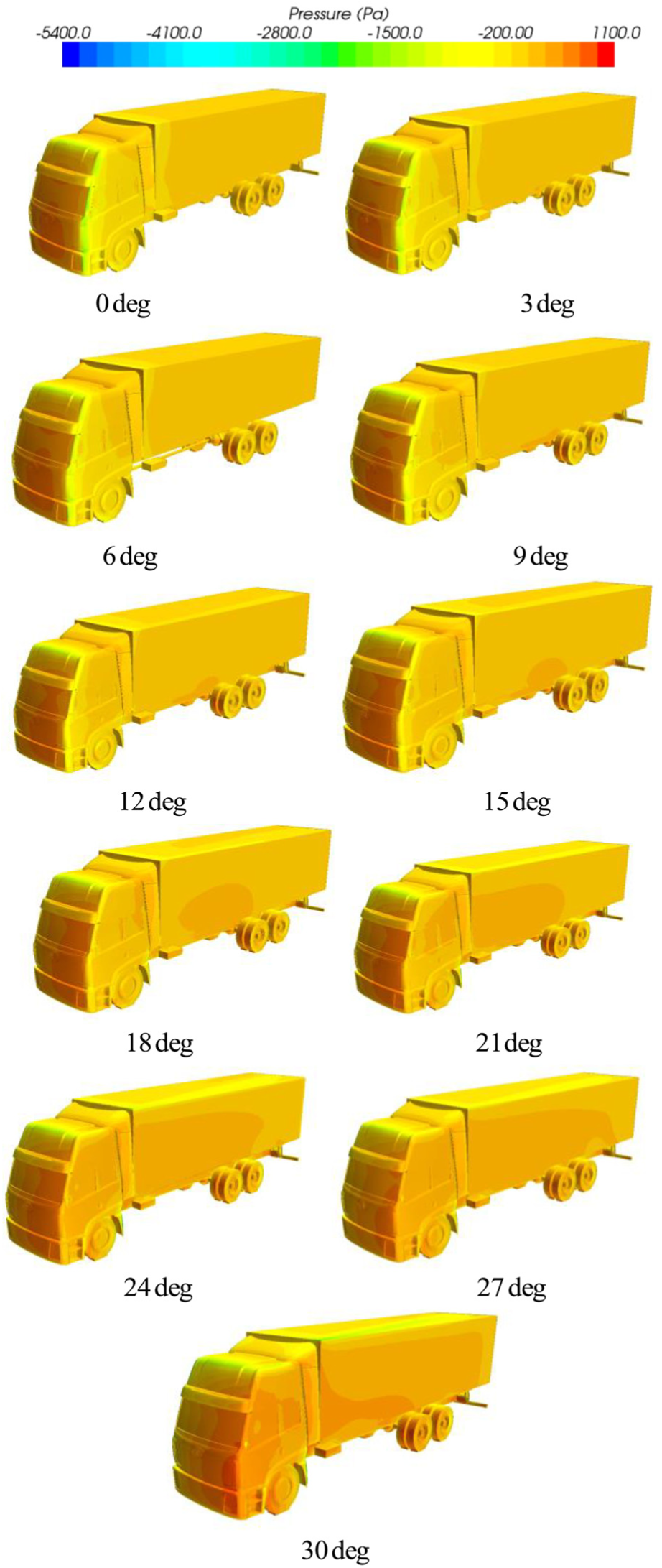
The pressure distribution on the surface of the truck.
In addition, the increased positive pressure area in the cab also means that aerodynamic drag of heavy truck is gradually increased. The growth trend of aerodynamic drag force of heavy truck can be seen from the pressure distribution.
The pressure distribution on the surface of cargo body shows a tendency to increase aerodynamic lift. With the increase of slide angle, the pressure on the upper surface of cargo body gradually shifts to the negative pressure. Due to the existence of the corner and the slide angle, the larger negative pressure area is obtained because of the formation of turbulence in the rear corner of cargo body.
Besides pressure distribution, velocity distribution and flow visualization were studied. Aerodynamic forces and moments can be obtained according to the pressure distribution.
Aerodynamic reference point of SAE
When air flows around a vehicle, it will be affected by the aerodynamic forces and moments. To determine the aerodynamic forces and moments, all aerodynamic forces and moments are described in a point, and that point is called as the aerodynamic reference point.
A pressure center is first proposed and used as aerodynamic reference point, and there are only aerodynamic forces in the pressure center.17–19 However, when intensity of the crosswind changes, the pressure center position of a vehicle also changes. Therefore, the pressure center position of a vehicle is not fixed.
To make aerodynamic reference point as an unchanged point, aerodynamic reference point of SAE is placed as a wheelbase mid-point along the intersection of vehicle vertical plane of symmetry and at the ground. 20 Aerodynamic reference point is also a coordinate origin point, the horizontal forward motion direction of vehicle is positive x-axis, the vertical upward direction is positive z-axis, positive y-axis is identified by the right-handed principle, and the coordinate system is fixed in vehicle, as shown in Figure 7.

Aerodynamic forces and moments of aerodynamic reference point of SAE.
Aerodynamic coefficient
The aerodynamic properties of three aerodynamic forces and three moments are defined as aerodynamic drag, side force, lift, roll moment, pitch moment, and yaw moment, respectively, at aerodynamic reference point of SAE, and they are expressed as follows


where
Three aerodynamic forces and three moments can be established by wind tunnel test or CFD simulation, and then six aerodynamic coefficients are solved by equations (3)–(8). For each slide angle, there are six aerodynamic coefficients. Therefore, aerodynamic coefficients can be a function with the slide angle as a variable.
Aerodynamic result comparison
Both CFD simulation and wind tunnel test of the heavy truck model are carried out when slide angle is less than 15°. The result comparison between CFD and wind tunnel test for six slide angles is shown in Figure 8.

Result comparison between CFD simulation and wind tunnel test of aerodynamic coefficients for six slide angles.
It can be seen that there is a little difference between the two results, and their relative error is within 5%. As a result, CFD simulation can be used in crosswind aerodynamics research of heavy truck, and all aerodynamic coefficients for 11 slide angles are obtained by CFD simulation.
Aerodynamic coefficient description
Aerodynamic coefficients of heavy truck under crosswind are obtained with CFD simulation for 11 slide angles, they are expressed as slide angle curves, and numerical fluctuation is removed. Six aerodynamic coefficients are fitted with polynomial, and the fitted formulas are written as


Vehicle dynamics simulation
TruckSim
TruckSim was developed by the American Mechanical Simulation Corporation, and it is an MBS dynamics software of vehicle for modeling, simulating, and analyzing complex truck behaviors based on performance parameters. TruckSim combines information from graphical data interfaces with vehicle dynamics math models to simulate truck behaviors. TruckSim also links the simulation results with animation and plotting programs, as shown in Figure 9.

Four components of TruckSim.
TruckSim vehicle model is divided into aerodynamics, body, driving system, steering system, braking system, and powertrain system, as shown in Figure 10.

Vehicle dynamic model of TruckSim.
Modeling and simulation setup
In TruckSim simulation, a heavy truck is set up according to the design and measuring data from a truck manufacturer in China. The equations (9)–(14) are expressed in TruckSim, and the internal program of TruckSim will calculate the aerodynamic forces and moments automatically based on simulation setup.
When a heavy truck is driven on road, sudden direction changes and discontinuous crosswind might seriously affect the driver’s judgment. If the driver responds inappropriately, an accident such as vehicle rollover may occur.
In order to study how the sudden direction changes and discontinuous crosswind affect stability and response characteristics of heavy truck, simulation condition of heavy truck is set up under direction changes and discontinuous crosswind, as shown in Figure 11.

Simulation condition of direction changes and discontinuous of crosswind.
The heavy truck runs straight at a speed of 22.22 m/s, then the speed of crosswind is set to 12 m/s at a location of 20 m. The vehicle runs continuously under the crosswind effect for about 30 m. After that, the vehicle runs without crosswind about for 30 m, and then the speed of crosswind is set to −12 m/s for about 30 m. At last, the vehicle runs under no crosswind for about 10 m. The crosswind direction changes with time as shown in Figure 12.
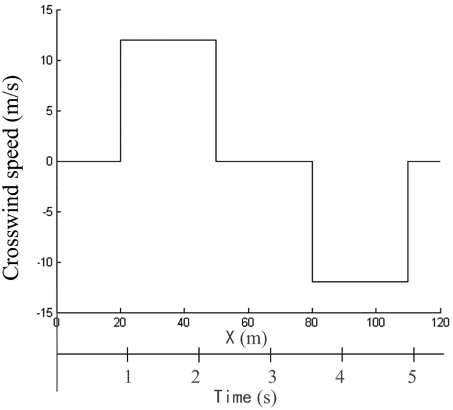
Crosswind direction changes setup.
Open loop means that the driver does not do any manipulation correction when a vehicle is disturbed, that is, the driver does not play any control role. Open-loop test or simulation can directly reflect the characteristics of the vehicle without driver’s operation, and it is the inherent characteristic of the vehicle itself.
Closed-loop means that the driver does manipulation correction when a vehicle is disturbed, that is, the driver plays a control role. Closed-loop test can directly reflect the driver’s operation influence on vehicle handling and stability.
The driver control is set up in TruckSim, the driver’s reaction time is 0.15 s and the preview time is 1.5 s. Under the same crosswind condition, the results of open-loop simulation are compared with closed-loop simulation.
Results of sudden and discontinuous direction changes of crosswind
Under sudden direction changes and discontinuous crosswind condition, open-loop and closed-loop simulations of heavy truck are completed in TruckSim, respectively. Vehicle trajectory, roll rate, lateral acceleration, yaw rate, and steering wheel angle of the vehicle are shown in Figure 13.

Simulation results of the sudden direction changes and discontinuous crosswind: (a) vehicle trajectory, (b) roll rate, (c) lateral acceleration, (d) yaw rate, and (e) steering wheel angle.
In Figure 13, it can be seen that the maximum lateral offset is about 1.55 m in open-loop simulation due to the crosswind effect. For open-loop and closed-loop simulations, the trend change of roll rate is slight, their value alternates from negative to positive, and the range is −1.49°/s to 1.695°/s. In open-loop simulation, the value of lateral acceleration alternates from positive to negative and its range is −0.497 m/s2 to 0.447 m/s2. In closed-loop simulation, the value of lateral acceleration alternates from positive to negative, then tends to 0, and its range is −0.467 m/s2 to 0.434 m/s2. In open-loop simulation, the value of yaw rate changes from positive to negative, and its range is −1.36°/s to 1.284°/s. In closed-loop simulation, the value of yaw rate changes from positive to negative, then to positive, and its range is −0.703°/s to 0.815°/s. The trend of yaw rate in open-loop is greater than the one in closed-loop simulation. The driver’s steering wheel angle is 0 in open-loop simulation, while the range of wheel steering angle is −26.648° to 24.845° in closed-loop simulation.
From the above results, it shows that the driver’s steering is very frequent in order to maintain the trajectory straight under sudden direction changes and discontinuous crosswind condition. If the driver does not participate in correction, the vehicle obviously deviates from the trajectory. If the vehicle is continuously affected by the crosswind, and the driver has to correct endlessly, it can easily result in driver’s fatigue and wrong operation. If the driver operation is slightly improper in this period, the driving safety would be threatened.
Discussion and conclusion
The method of yaw model is applied to analyze the aerodynamic characteristics of a heavy truck both in CFD simulation and wind tunnel test.
CFD simulation and wind tunnel test are used to investigate six aerodynamic forces and moments of a heavy truck at the same slide angles between 0° and 15°. The results of CFD simulation and wind tunnel test are compared, the comparison shows that there is little difference between both results, and their relative error is within 5%. As a result, the validity of CFD simulation results could be obtained by comparing with the wind tunnel test.
When slide angle is larger than 15°, both the ratio of the frontal area of the heavy truck to cross-sectional area of wind tunnel test section and the ratio of front projection width of the heavy truck to test section width of wind tunnel do not meet the aerodynamic test requirements. Therefore, CFD simulation is used to study aerodynamic characteristics of the heavy truck. Computation domain determination, mesh generation, solution set, and simulation are finished with STAR-CCM+, and accurate results of aerodynamic characteristics are obtained for the heavy truck.
The aerodynamic reference point of SAE, instead of pressure center, is used to establish aerodynamic forces and moments in CFD simulation and wind tunnel test. This point is an accurate and only position for any a vehicle and is not affected by any factors. It is also used in TruckSim to integrate CFD software and MBS software to complete combined simulation of the heavy truck. At this point, six aerodynamic coefficients of the heavy truck are obtained, and they could be expressed as a function with the slide angle as a variable, respectively.
TruckSim is an MBS vehicle dynamics software of vehicle simulation and consists of aerodynamics, body, driving system, steering system, braking system, and powertrain system. To analyze dynamics of a heavy truck, body, driving system, steering system, braking system, and powertrain system are built with the produced heavy truck in TruckSim, and its modeling effectiveness are proven by tests of the heavy truck manufacture. Aerodynamic coefficients of the heavy truck under crosswind are imported aerodynamics of TruckSim to evaluate crosswind behaviors of the heavy truck.
The response characteristics and stability of the heavy truck is simulated using TruckSim under sudden and discontinuous direction changes of crosswind, and the results show that the driver must handle the steering wheel to the right first and then to the left in a short time to keep the vehicle straight if the state happened. If the driver does not correct the steering wheel, the vehicle is obviously to offset road and may cause an accident trajectory. If the vehicle is continuously affected by crosswind and the driver has to correct endlessly, it easily results in fatigue and danger. If the operation is slightly improper in this period, the driving safety would be threatened. In this study, all the response characteristics are significant in the context of self-driving trucks and design effective control systems.
Footnotes
Handling Editor: Chengzhi Yuan
Declaration of conflicting interests
The author(s) declared no potential conflicts of interest with respect to the research, authorship, and/or publication of this article.
Funding
The author(s) disclosed receipt of the following financial support for the research, authorship, and/or publication of this article: This work is supported by the China Automobile Industry Innovation and Development Joint Fund (grant no.: U1564213), the International Cooperation and Exchange of the National Natural Science Foundation of China (grant no.: 61520106008), the National Natural Science Foundation of China (grant no.: 11702109), and the China Postdoctoral Science Foundation (grant no.: 2014M551179).