
Abstract
A modified rule of mixtures is required to account for the experimentally observed nonlinear variation of tensile strength. A modified Halpin–Tsai model was presented to predict the Young’s modulus of multiscale reinforced composites with both micron-sized and nano-sized reinforcements. In the composites, both micron-sized fillers—carbon fibers—and nano-sized fillers—rubber nanoparticles and carbon nanotubes—are added into the epoxy resin matrix. Carbon fibers can help epoxy resins increase both the tensile strength and Young’s modulus, while rubber nanoparticles and carbon nanotubes can improve the toughness without sacrificing other properties. Mechanical experiments and scanning electron microscopy observations were used to study the effects of the micron-sized and nano-sized reinforcements and their combination on tensile and toughness properties of the composites. The results showed that the combined use of multiscale reinforcements had synergetic effects on both the strength and the toughness of the composites.
Introduction
Direct extrusion fabrication (DEF), a new branch of solid freeform fabrication (SFF), 1 is an automated fabricating process that builds three-dimensional (3D) complex structures layer by layer directly according to computer-aided design (CAD) files without specific tooling of part, heating, and human intervention. The development of DEF has provided opportunities to fabricate complex structures and highly integrated systems that cannot be easily manufactured by conventional approaches.1–4 With the rapid development of new materials, the advantage of DEF is increasingly obvious day by day. Theoretically, DEF could adopt any pasty and gel-like composite material with additions, as long as it has good shape maintenance to support itself while printing.
Thermosetting epoxy resin (EP)-based composites have been widely used in many fields because of their wide range of advantages, including low weight, relatively high strength, and good chemical resistance.5–8 Recently, it is a trend that more and more metal structures have been replaced by lightweight polymer. The Young’s modulus values of thermosetting EPs are an order of magnitude higher than those of photocurable and thermoplastics resins used in commercial 3D printing methods. However, EPs also have a few drawbacks, such as brittle fracture properties and poor crack propagation resistance, which restrict their applications. 9 Therefore, a number of researchers have presented some modification methods to improve the mechanical performance of EP-based composites. These methods include micron-sized modification and nano-sized reinforcing modification.9–11
Nowadays, the common modification methods that are used to improve the mechanical performance of EPs include micrometer-scale filler modification and nanometer-scale filler modification. Carbon fibers (CFs) are one of the most commonly used micrometer-scale fillers in EPs. CF reinforcement includes continuous CFs and short CFs. In comparison with continuous CF-reinforced composites, short CF-reinforced composites show superiority in their uncomplicated preparation techniques, good isotropy, and low cost. However, in general, short CFs have worse general mechanical performance than continuous CFs. Therefore, more attention should be paid to the automobile, aerospace, and construction industries. Kaynak et al. 12 concluded that micrometer-scale CFs can help enhance the impact strength and Young’s modulus of the EP composites simultaneously.
Recently, carbon nanotubes (CNTs) are usually used as a second microphase to modify EPs. The discovery of CNTs can be retrospected to the discovery of fullerene chemistry.13–15 In 1991, Iijima 16 discovered CNTs that are an elongated tube form of fullerenes with hexagonal carbon walls. Traditionally, there are two types of CNTs: single-walled carbon nanotubes (SWCNTs) and multi-walled carbon nanotubes (MWCNTs). The former got its name from a single graphene cylinder. On the contrary, MWCNTs contain two or more homocentric cylindrical graphene sheets surrounded by a hollow core with graphitic interlayer separations. CNTs are a type of approximate one-dimensional (1D) wirelike materials with distinguished mechanical, thermal, and electronic properties. 17 CNTs have attracted much attention in science and engineering because they provide the stiffest fiber reinforcement with polymers and other materials.18–20 Compared with spherical nanoparticles, CNTs have high aspect ratios of 100 or more and distinctive specific surface area. These conditions contribute to the excellent stress transmission ability due to the good interfaces.21,22 Although much work has been done on CNT-reinforced EP, the fracture properties can only be improved to a limited degree. Therefore, more effective methods for further improvement of fracture toughness of the EPs are needed.
However, either CF-reinforced or CNT-reinforced method cannot enhance the fracture toughness of the EPs effectively. Researchers indicated that nano-sized rubber particles can impressively improve the fracture toughness of the EP. 23 However, the problem is that the properties such as modulus and tensile strength might decrease drastically with the addition of the nano-sized rubber particle phase. 24 Recently, the main challenge for toughening EP-based composites is to increase the toughness without sacrificing other properties. In recent years, more and more researchers have introduced rubber nanoparticles (RNPs) into the EPs to enhance their mechanical properties. Sue et al. 25 indicated that the RNPs can enhance both the tensile strength and the fracture toughness of the EPs effectively. Ma et al. 26 stated that the RNPs can strengthen the EPs as effectively as the micron-sized fillers without decreasing the Young’s modulus.
In order to improve the strength and toughness of EPs simultaneously without sacrificing other key properties, both micron-sized and nano-sized reinforcements were used to synergistically modify the EP matrix in this study. Recent studies have shown that different scaled reinforcements can compensate for each other in strengthening the EPs. Rahmanian et al. 27 found that EP-based composites reinforced with both CNTs and CNT-grown CFs had better tensile strength, Young’s modulus, and impact resistance than the CNTs/epoxy or CNT-grown CFs/epoxy composites. Zhang et al. 28 and Sharma and Lakkad 29 stated that multiscale carbon reinforcements had synergetic effects on both the strength and fracture properties of EPs. In this study, short CFs, RNPs, and CNTs were used to modify the EP matrix. The synergetic effects of multiscale reinforcements on the tensile strength and toughness properties were discussed.
Experimental
Materials
In this article, Epon 826 (Shell Co., Ltd, The Netherlands) polymer is chosen as the matrix material. The macron-scale reinforcement is T700SC-12000-50C (Toray Co., Ltd, Japan) short CFs and the nanoscale reinforcements are RNPs (Beijing Institute of Sinopec. China) and CNTs (Xianfeng Nano Technology Co., Ltd, China). The details are listed in Tables 1–3.
Main performance indexes of EP matrix.
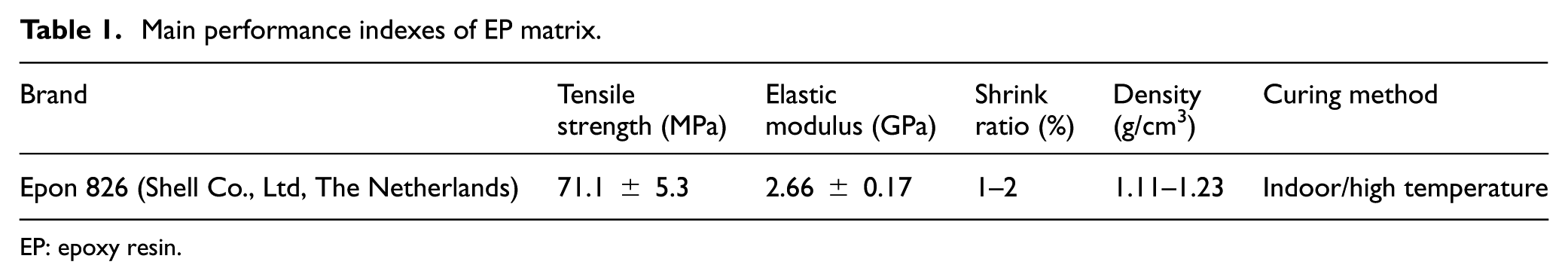
EP: epoxy resin.
Main performance indexes of CFs.
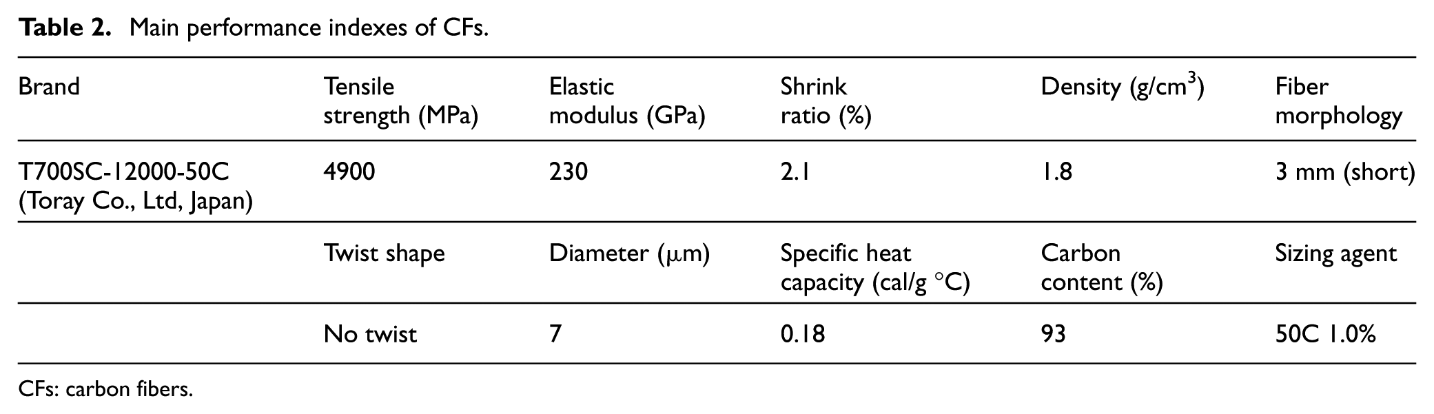
CFs: carbon fibers.
Main performance indexes of nano-sized fillers.

Preparation
In order to improve the interfacial bonding condition between CFs and EP, CFs should be surface treated. First, the CFs were milled in a planetary ball milling machine (QM-ISP4, Nanjing University Instrument Plant, China) for 15 min, the rotation speed was set at 150 r/min, and the ball–material ratio was 20:1. This is the first physical step for surface treatment of CFs, in which the sizing agent and the amorphous carbon on the surface of CFs were removed. As a matter of experience, CFs could be truly useful as a reinforcement in the EP matrix only when the average length is larger than 500 μm. The average length of CFs is inversely proportional to the milling time. That means long milling time will cause short average length of CFs. In this study, the average length of CFs after 15-min milling is 885 μm.
After that, they were put into a Soxhlet extractor for 48 h with acetone as the extraction medium. After drying, they were immersed in nitric acid (65vol.%) for 2 h under sonication. Next, they were immersed in a coupling agent (KH550, 25vol.%) for 1 h. Afterward, the treated CFs were washed with deionized water and dried in an oven at a temperature of 80°C.
Table 4 shows the surface morphology of the CFs before and after treatment. The CF specimen is divided into four groups: A—untreated CFs, B—CFs treated only by ball milling, C—CFs treated after 15-min ball milling and liquid-phase oxidation/sonication, and D—CFs treated after 60-min ball milling and liquid-phase oxidation/sonication. Specimen A showed a smooth surface, and the corresponding root mean square (RMS) roughness was 54.5 nm. After being treated by ball milling, the RMS of the CFs increased to 168.7 nm. When the CFs were treated after 15-min ball milling and liquid-phase oxidation/sonication, the RMS reached 396.8 nm and some grooves can be observed along the radial direction. Although specimen D shows a larger roughness than specimen C, the average length of specimen D is 143 μm, which is not suitable for reinforcement.
Root mean square (RMS) roughness of the CF specimens.

CF: carbon fiber.
The blend (EP + CFs) was stirred by a high-speed planetary stirrer for 5 h at a speed of 3000 r/min; after that, CNTs were put into the blend and treated with ultrasonic for 0.5 h at 25°C. Next, the curing agent was added into the blend (stirring for another 3 h). Finally, the samples were cooled to indoor temperature.
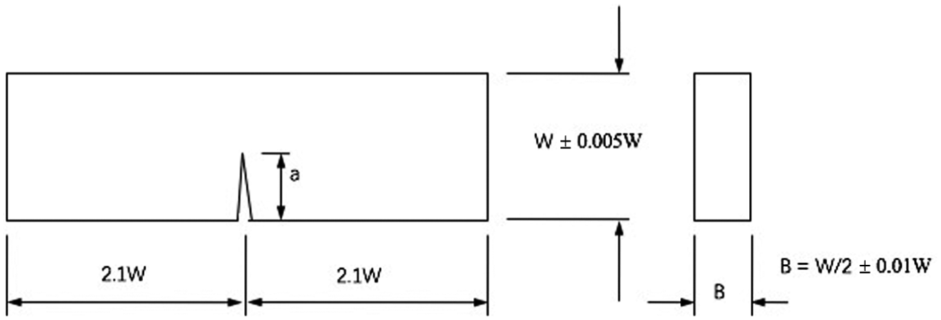
The tensile strength was tested using an SANS CMT5105 universal testing machine at a temperature of 25°C according to ASTM D638-2010 standard. The measurements were performed at a speed of 5 mm/min, and five specimens were used for every test after 30-min tempering at a temperature of 60°C. The fracture toughness was tested by single-edge notched bend (SENB) specimens in accordance with ASTM E-399 and GB4161-84 standards. The specimens were cured in steel molds with the dimensions of 42 × 10 × 5 mm3. The tests were performed at a speed of 5 mm/min. Figure 1 shows the sketch of the composition. According to the standard, the height W and thickness B should satisfy the relationship of W/B = 2, the height W and the length S should satisfy W/S = 4.2, and the length of the crack a should satisfy a/W = 0.45–0.55. To guarantee the accuracy of the testing, the perpendicularity between the notch and the base should be within ±2°.
The sizes of specimen according to the standard.
The fracture toughness in this study was calculated in terms of KIC. In equation (1), Y represents the shape factor of the cracks, Pf is the indentation load, S is the support length at the bottom, which is 4 ± 0.2 W in Figure 2, B is the thickness of the specimen, W is the height of the specimen, and a represents the length of the crack. 30 Poisson’s ratio was 0.35 31


Schematics of measurement according to the GB4161-84 standard.
Results and discussion
Tensile strength
The rule of mixtures (ROM) is a simple and approximate way of predicting the tensile strength of fiber-reinforced composites. However, the ROM is not an effective way of estimating the tensile strength and it fails to predict accurately the tensile strength due to many factors: stress and strain raisers due to embedded reinforcements, interface failure, statistical dispersion effects, void presence, misalignments, and so on. ROM is not useful in the transverse directions for continuous fiber composites. The basic principle of ROM is the evaluation of the contribution of the fiber and the matrix at the point of failure. In fact, the tensile strength of a composite is affected not only by the fiber and matrix fractions but also the interconnecting and mixing pattern of each composite component. In the ideal ROM, fibers in the composite are unidirectionally aligned and uniformly distributed, but in reality the fibers have some nonhomogeneity of spread and misalignment of orientation. As a result, the ROM often overestimates the ultimate tensile strength of unidirectional fiber composites.
In this article, a modified ROM was developed, which could realize a more accurate prediction of tensile strength of a wide range of fiber volume fractions. The factors influencing strength degradation were considered. We found that the difference between the experimental tensile strength and the one predicted by the ROM is mainly due to the difference between the expected and real contributions of fibers to the tensile strength of the composite.
The ROM before modification, which is for a unidirectional reinforced continuous composite, ideally aligned, can be expressed as follows

where
After considering the strength degradation factors,

where

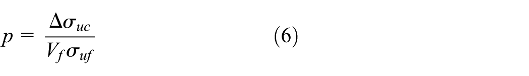
where p is the degradation factor for the effective fiber volume fraction and 0 < p < 1. p can be obtained from the microgeometry of the composite components and depends on the fiber volume fraction, because the microgeometry is mainly related to the fiber volume fraction under the same manufacturing conditions. Here, however, p is directly calculated from the experimental strength data because of the lack of microgeometrical data.
According to equations (2)–(4), there is

where
According to the experiments, the linear fitting picture of p obtained according to the volume fraction of fibers is shown in Figure 3.

The degradation factor p in effective fiber volume fraction with fiber volume fraction, where p is the degradation factor for the effective fiber volume fraction and 0 < p < 1.
The piecewise functions are as follows


According to the experiments, the slope change point is
Figure 4 compares the experimentally measured tensile strength of EPs/CFs composites with the prediction of modified ROM. The blue dashed line represents the prediction of ROM before modification, while the green curve indicates the prediction of modified ROM. The blue star points are experimentally measured tensile strength of EPs/CFs composites. The results indicate that the strength begins to decrease above a fiber volume fraction of about 60% in real composites, as mentioned earlier. It can be assumed that the model predicts the actual composite strength because we have defined p to account for the microgeometry of real composites. The relative error between the experimentally measured tensile strength of EPs/CFs composites and that predicted using modified ROM is given in Table 5. The negative value means the predicted value using modified ROM is smaller than that measured experimentally, and the prediction at 50% is the mean of the piecewise function value at 50%.
The relative error between the experimentally measured tensile strength of EPs/CFs composites and that predicted using modified ROM.

EP: epoxy resin; CF: carbon fiber; ROM: rule of mixtures.

Comparison of tensile strength values measured experimentally, predicted using modified ROM, and predicted using ROM before modification.
If p could be precisely obtained from the microgeometry of real composites using micrographs, the tensile strength of a composite can be predicted more accurately. In fact, p is not a function determined from the composite components but is mainly dependent on the manufacturing process of the composite.
Young’s modulus
Halpin 32 and Tsai developed a mathematical model for predicting the Young’s modulus of polymer composites. The model is

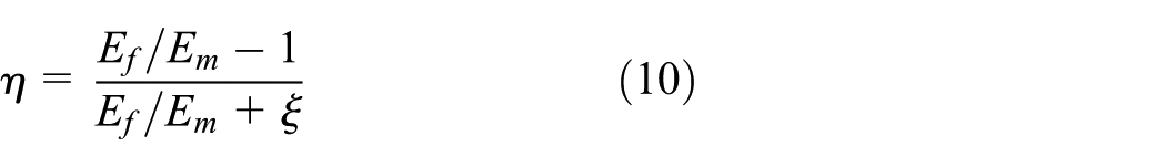

where “


where


where


where
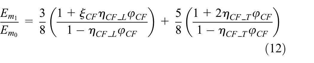
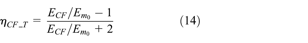
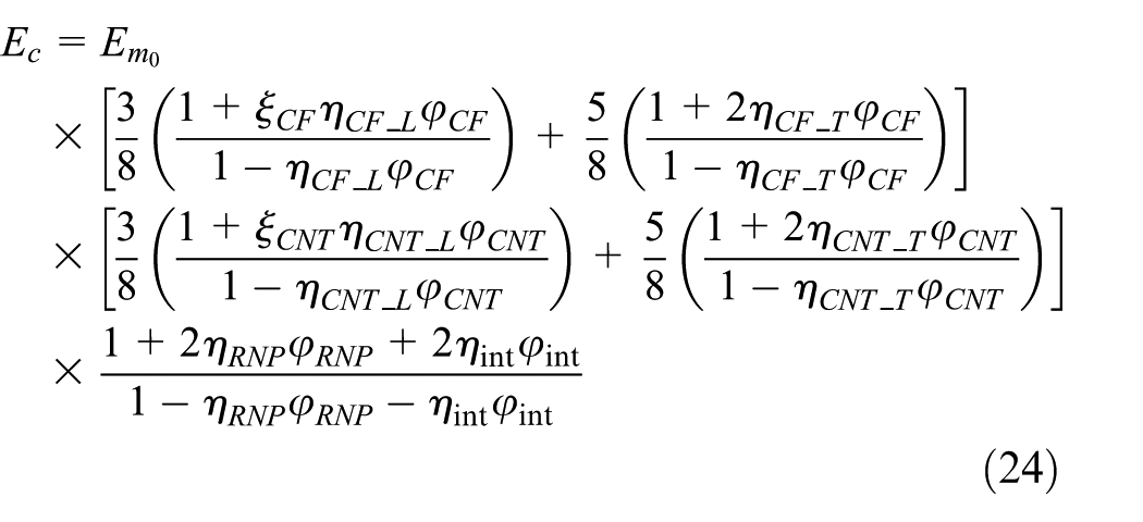
Therefore, based on the modified H-T equations given in equations (12), (16), and (20), the H-T model of multiscale composites can be obtained
In this study, the Young’s modulus values of the neat EPs (Table 1), CFs (Table 2), RNPs, and CNTs (Table 3) were 2.66 GPa, 1.2 TPa, 0.01 GPa, and 230 GPa, respectively. The average length and the average diameter of the CNTs were measured as 1.5 μm and 15 nm, respectively. The average diameter and the average length and of the treated CFs were 7 (as determined by atomic force microscopy (AFM) observations) and 885 μm (treated by ball milling, liquid-phase oxidation/sonication), respectively. The average radius of RNPs was 100 nm. Details on the parameters of the RNPs/EP interphase can be referred from the study by Y Zare. 35 The Young’s modulus of the interphase and the interphase thickness are 2.1 GPa and 35 nm, respectively.
Figure 5 and Table 6 shows the comparative elastic modulus between the experimental and theoretical values. Under the condition of constant contents of CFs (10 phr) and RNPs (4 phr), the relative errors are both larger than 10% when the contents of CNTs are 0 and 0.25 phr. However, when the contents of CNTs are increased to 0.5, 0.75, and 1 phr, the relative errors drop to 5% and below. “phr” means the percentage of additives in rubber (or resin), parts per hundreds of rubber (or resin). These indicated that the premises for the modified Halpin–Tsai models were not perfectly satisfied when the content of CNTs is low. So the interface failure may have occurred because the reinforcement/EP interfaces were imperfectly bonded. For the multiscale reinforced EP composites with both CFs and CNTs, the imperfect bonding has been improved. In particular, when the content of CNTs reaches 1 phr, the relative error increases. This is because the reaggregation phenomenon resulted from the high content of fillers.

The relative error between the experimental result and the theoretical value of Young’s modulus (the content of CFs is 10 phr and the content of RNPs is 4 phr).
The relative errors of the theoretical values and experimental results for the elastic modulus (the content of CFs is 10 phr and the content of RNPs is 4 phr).
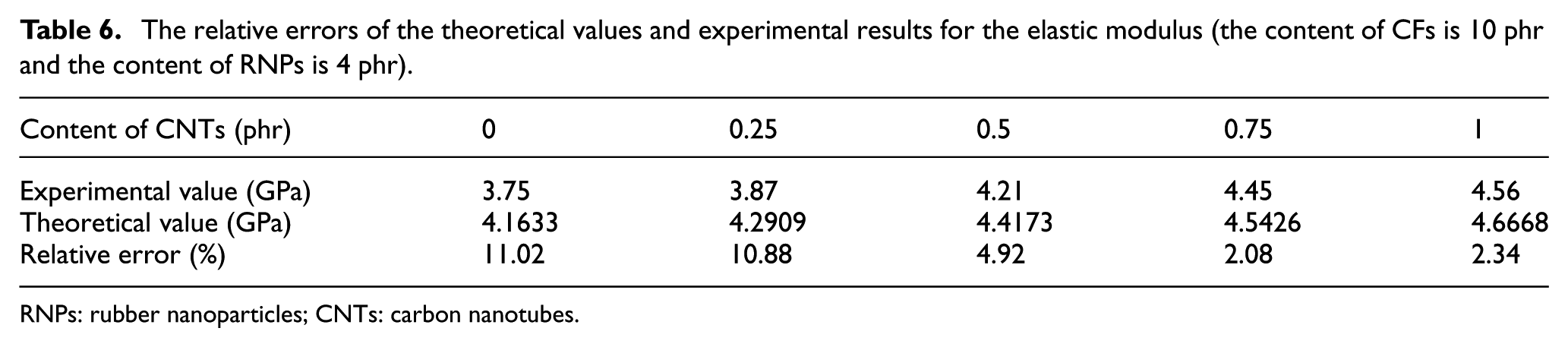
RNPs: rubber nanoparticles; CNTs: carbon nanotubes.
Fracture properties
We can see that the multiscale specimen of 15CF/0.75CNT/6RNP showed the best toughness properties shown in Figure 6. The KIC values of the specimens examined in this study are shown in Figure 6. This showed that KIC of neat EPs was 0.87 MPa m1/2. Obviously, the KIC values of the reinforced specimens all improved. Generally, the toughening mechanisms of the CFs include fiber breakage, fiber debonding, and fiber pullout. We found from Table 4 that the treated CFs had larger surface roughness and better wettability than the untreated ones. This will consume more energy when the CFs are broken, debonded, or pulled out from the matrix. The KIC values of 5CF, 10CF, 15CF, and 20CF were 1.12, 1.74, 1.82, and 1.56, respectively.
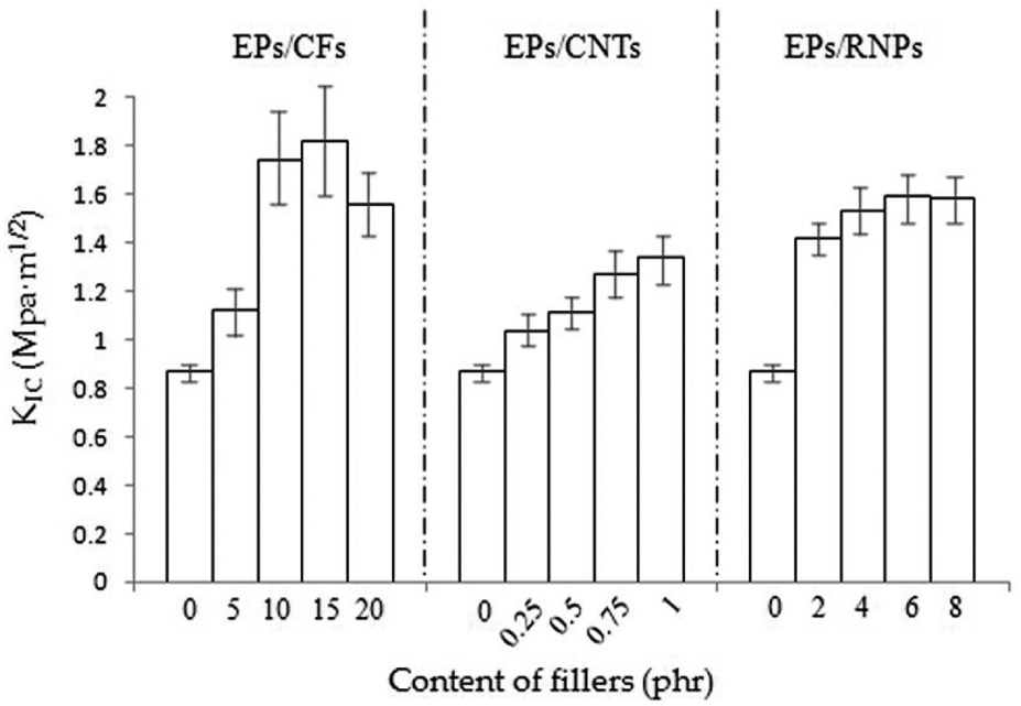
The fracture toughness of different contents of fillers (solely filled).
The KIC values of the CNT-reinforced specimens (0.25CNT, 0.5CNT, 0.75CNT, and 1CNT) were 1.03, 1.11, 1.27, and 1.34 MPa m1/2, respectively. Although the KIC increment of 1CNT was much less than that of 15CF, the addition content of CFs was 15 times that of CNTs. This demonstrated that the CNTs had more efficient effects on toughening of the EPs than the micron-sized CFs. Compared with the specimens solely reinforced by CFs, RNPs, or CNTs, the multiscale reinforced specimens with CFs, CNTs, and RNPs showed a synergetic enhancement in fracture toughness. From Figure 6, it can be seen that 15CF and 6RNP made their composites reach the peak KIC value, respectively. However, the CNT/EP composites did not show a peak value from 0 to 1 phr. In this article, when the content of CNTs is larger than 1 phr, the reaggregation phenomenon occurred. Therefore, the content of CNTs is set to be the variable for the synergetic effect.
From Figure 7, we can see that KIC of 15CF/6RNP/0.75NT reached 3.04 MPa m1/2, which is 349.4% of the neat EP; this caused a new increase when the content of CFs or RNPs exceeded 15 or 6 phr, respectively. In other words, the combined reinforcements went beyond the limits of solely filled composites in fracture toughness. Therefore, the CFs, RNPs, and CNTs had synergetic effects on the toughness performance of the EPs.

The fracture toughness of different contents of fillers (multiscale reinforced).
In order to intuitively represent the fracture properties of the multiscale reinforced composites, scanning electron microscopy (SEM) micrographs of the fracture surfaces are shown in Figure 8. The specimen of EPs showed a smooth fracture surface (Figure 8(a)), which means a brittle fracture. After being filled with CF, RNP, and CNT reinforcements, a much rougher fracture surface with plastic deformation areas (Figure 8(b)) was observed. On the one hand, nano-sized fillers have a larger specific surface area than micron-sized fillers, so they can help improve the stress transfer ability. On the other hand, because the dimension of nano-sized fillers is much smaller than that of micron-sized fillers, the debonding and pullout mechanisms have been enlarged. This means that nano-sized fillers can help prevent the cracks from propagating inside the composites.

SEM micrographs of the fracture surfaces: (a) EPs and (b) 15CF/6RNP/0.75CNT.
Conclusion
In this article, a new type of EP-based composite materials, which is modified by multiscale reinforcements, for DEF is developed.
The micron-sized fillers (CFs) are treated by ball milling and liquid-phase oxidation/sonication in order to increase the surface roughness and thus improve the interfacial interactions. CFs were mainly used to increase the tensile strength and Young’s modulus of the EP-based composites. A modified ROM, which considered the strength degradation caused by nonhomogeneity of spread and misalignment of orientation of the fibers, was presented to accurately predict the tensile strength of CFs/RPs composites. Based on the classical Halpin–Tsai equations, a modified model, which can be used to predict the Young’s modulus of the multiscale composites reinforced with CFs, RNPs, and CNTs, was developed. From the results, it can be seen that the relative errors between the theoretical and experimental values were smaller than 10% when the content of CNTs is larger than 0.25 phr.
For the sake of increasing the toughness of EP composites without sacrificing the strength, nano-sized fillers, such as RNPs and CNTs, were added. The results showed that the multiscale reinforcements (micron-sized and nano-sized) had synergetic effects on both the tensile strength and fracture toughness. KIC of 15CF/6RNP/0.75NT composites reached 3.04 MPa m1/2 (349.4% of the neat EP), which caused an additional increase in toughness compared to solely reinforced composites. The addition of nano-sized fillers contributed to improve the interfacial interactions in the composites. Furthermore, the addition of nano-sized fillers contributed to the plastic deformation of the composites.
Footnotes
Handling Editor: Jianqiao Ye
Declaration of conflicting interests
The author(s) declared no potential conflicts of interest with respect to the research, authorship, and/or publication of this article.
Funding
The author(s) received no financial support for the research, authorship, and/or publication of this article.