
Abstract
This article explores the construction of a geometric virtual reality platform for the environmental navigation. Non-panoramic photos and wearable electronics with Bluetooth wireless transmission functions are used to combine the user’s actions with the virtual reality environment in a first-person virtual reality platform. The 3ds Max animation software is used to create three-dimensional models of real buildings. These models are combined with the landscape models in Unity3d to create a virtual campus scene that matches real landscape. The wearable device included an ATMega168 chip as a microcontroller; it was connected to a three-axis accelerometer, a gyroscope, and a Bluetooth transmitter to detect and transmit various movements of the user. Although the development of the mechatronics, software, and engineering involved in the three-dimensional animation are the main objective, we believe that the methods and techniques can be modified for various purposes. After the system architecture was created and the operations of the platform were verified, wearable devices and virtual reality scenes are concluded to be able to be used together seamlessly.
Introduction
Virtual reality (VR),1–8 as the term suggests, is the simulation of a real environment, or the creation of a fictional world using visual, auditory, tactile, and other stimuli, for a specific purpose. Kim Pallister, the Director of Content Strategy for Intel’s Visual Computing Team, vividly describes how VR works by deceiving the senses. The development of VR technology is closely related to the progress of computer technology because the quality of three-dimensional (3D) images9–11 and the effectiveness of sensors depend on computing speed. Some time ago, the slowness of machines, small memory capacities, and the immaturity of integrated circuits and imaging technology all caused the development of VR to proceed very slowly, and associated equipment was extremely expensive. In recent years, computer technology has been developing rapidly, overcoming some past difficulties, and eliminating many of the restrictions on developers. As the prices of hardware fall, almost everyone has a computer and a mobile phone. The production capacity for VR platforms and the range of conditions under which VR can be used are increasing daily. Therefore, the number of ways to use VR technology is increasing, and this technology is adding value to businesses.
With the rapid development of science and technology, the maturing of virtual technology, and the growing popularity of wearable devices, VR is being used more widely. It is currently used in advertising, gaming, architecture, teaching, navigation, medicine, sales, product development, and professional simulation. Many new virtual products are emerging. Video game companies are increasingly working on projects that use VR or augmented reality12–15 (AR), often cooperating with VR and AR hardware manufacturers to launch new games in the marketplace. The “Pokémon Go” mobile game is a good example. The latest VR wearable devices include HTC Vive, Sony Project Morpheus, and Oculus Rift.
This article concerns the future of VR with environmental navigation as a core theme and an eye to the use of hardware and software to produce better interactive geometric virtual realities. We hope that a more convenient modeling technology with lighter and more responsive wearable devices and more realistic 3D scenes will ensure the bright future of VR.
The development of the mechatronics, software, and engineering involved in 3D animation are the main objective, we believe that the methods and techniques can be modified for various purposes. The contribution of this article is as follows: a geometric VR platform for the environmental navigation has been finished and the operations of the platform verified; wearable devices and VR scenes are demonstrated to be able to be used together seamlessly.
Environmental navigation system architecture
The system consists of two main elements—the virtual scene and the action navigator. The elements of the virtual scene include the 3ds Max virtual building models, the campus model in Unity3d, and the C# program code. The action navigator consists of a three-axis accelerometer, a gyroscope, a Bluetooth transmitter, and 3D glasses. See Figure 1.

System architecture.
Design of wearable equipment
VR is not only about images, but it also depends on special responses, such as visual interactions, and sonic, light-related, and vibrational responses to movements of the user, such as raising hands, turning the head, or swinging the body. A wearable device is important in making these effects realistic.
The main function of the wearable device in this article is to measure head movements, such as nodding, and left and right turns. Accordingly, a three-axis accelerometer and a gyroscope are used. The three-axis accelerometer detects acceleration along the Y-axis, such as during nodding or raising a hand. The gyroscope detects changes in the angular velocity that are associated with the left and right turns of the head. Head movements, transferred as signals, are detected by a somatosensory signal transmission board and sent to a Bluetooth signal receiver board using wireless signal transmission (Figure 2). From the signal receiver board, the signal is sent to the Unity3d using RS232 serial communication. The signal from the somatosensory transmission board is sent to 3D glasses, which were designed and printed by the authors (Figure 3). A movement of the user’s head causes Unity3d to receive a signal, which is transformed into interactive effects on the screen.
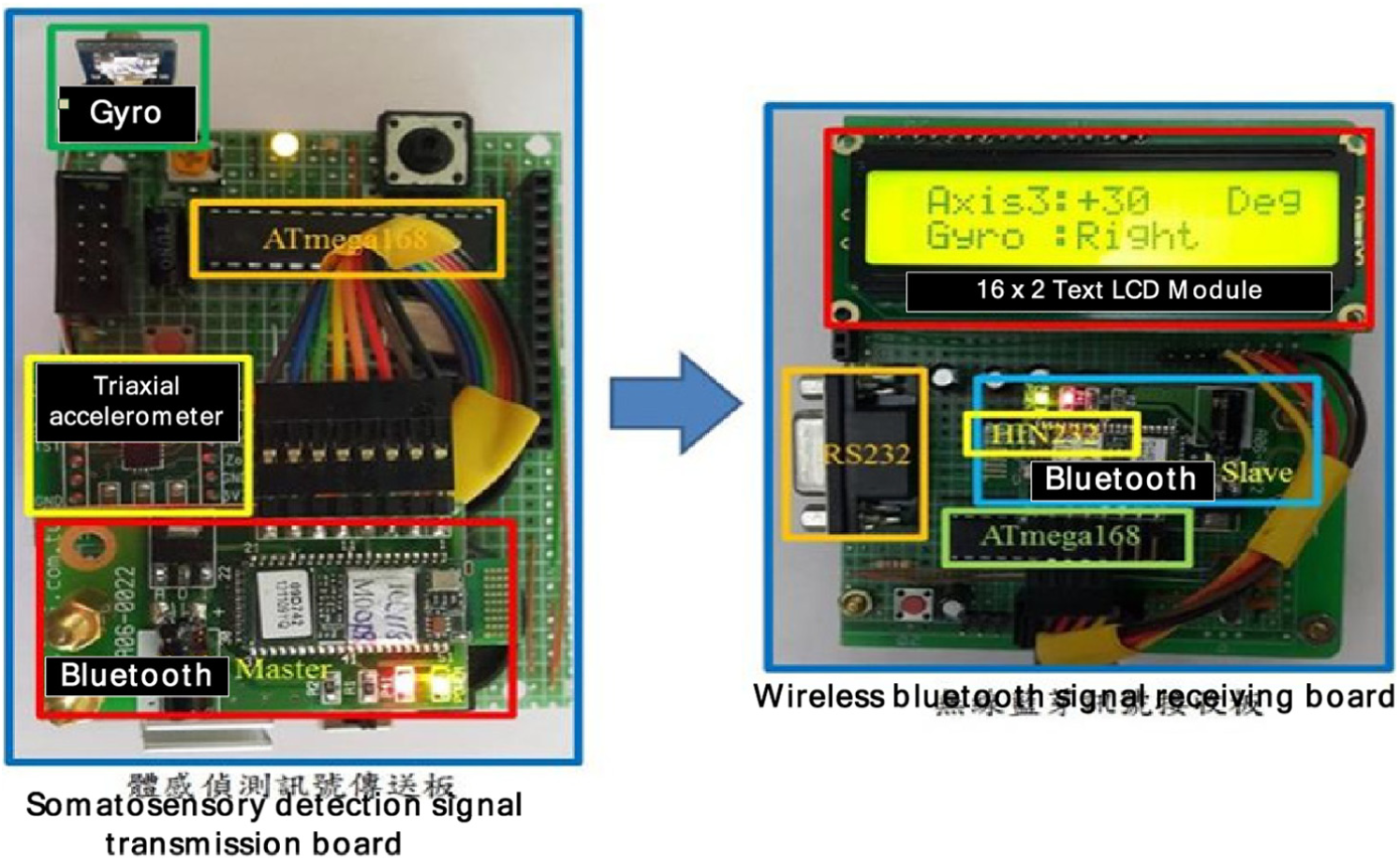
Signal transmitting and receiving board.
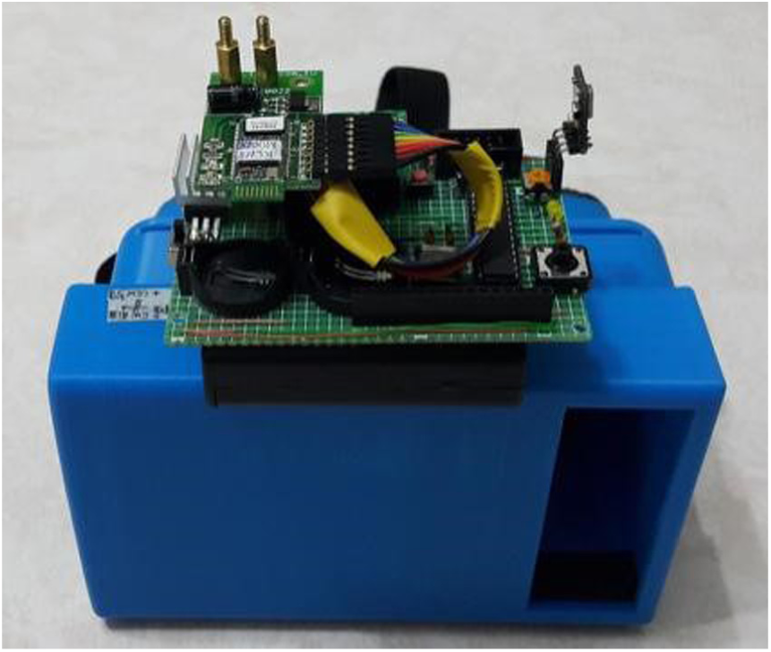
Somatosensory signal transmission board and 3D glasses.
Modeling in 3ds Max
As we wanted to create the campus environment with an appearance as close to reality as possible, we drew many 3D models one by one in the actual scale. After the campus was planned, the models were produced in the 3ds Max software (Figure 4).

Model creation in 3ds Max 9.
Head motion detection circuit
The main function of the VR wearable device is to connect the user’s actions with the virtual scene to provide the feeling of engaging with reality. Therefore, the design of the wearable device should be related to the conditions under which it will be used to achieve the best results. In this article, 3D glasses through which the virtual campus can be seen are designed; they enable interactions between the virtual world and head movements. The main role of the electric circuit is to detect the user’s head movements. The 3D glasses screen image is simulated on a computer screen. When a head movement is detected, the transmission board sends the associated signal to Unity3d, then through the Bluetooth Master port to the Slave port of the receiving board, and then through the RS232 serial communicator, as shown in Figure 5.
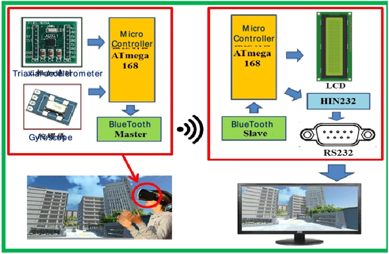
Circuit design and detection of head movement.
Creating geometric virtual campus
As our goal was to create a virtual campus, one of the first steps was to make the 3D models of each building. The final look of the virtual campus depended on the refinement of each model. After the models had been created, all of them were input to the Unity3d game engine. In the final step, we had to add specific physical properties to the object and write the program code.
As shown in Figure 6, since the modeling work took a long time, only the outsides of buildings were modeled to ensure that the project would be finished on schedule. The landscape around the campus, except for the stores and shops close to it, was created using the Unity3d landscape features.

The scheme of the campus.
Detailed views of 3D models
A scale version of real buildings was constructed. The real gymnasium roof, triangle windows, transom windows, doors, other windows, the left side wall of the gymnasium, and the restroom are shown in Figure 7. The placement of the 3D model, shown in Figure 8, is described below.
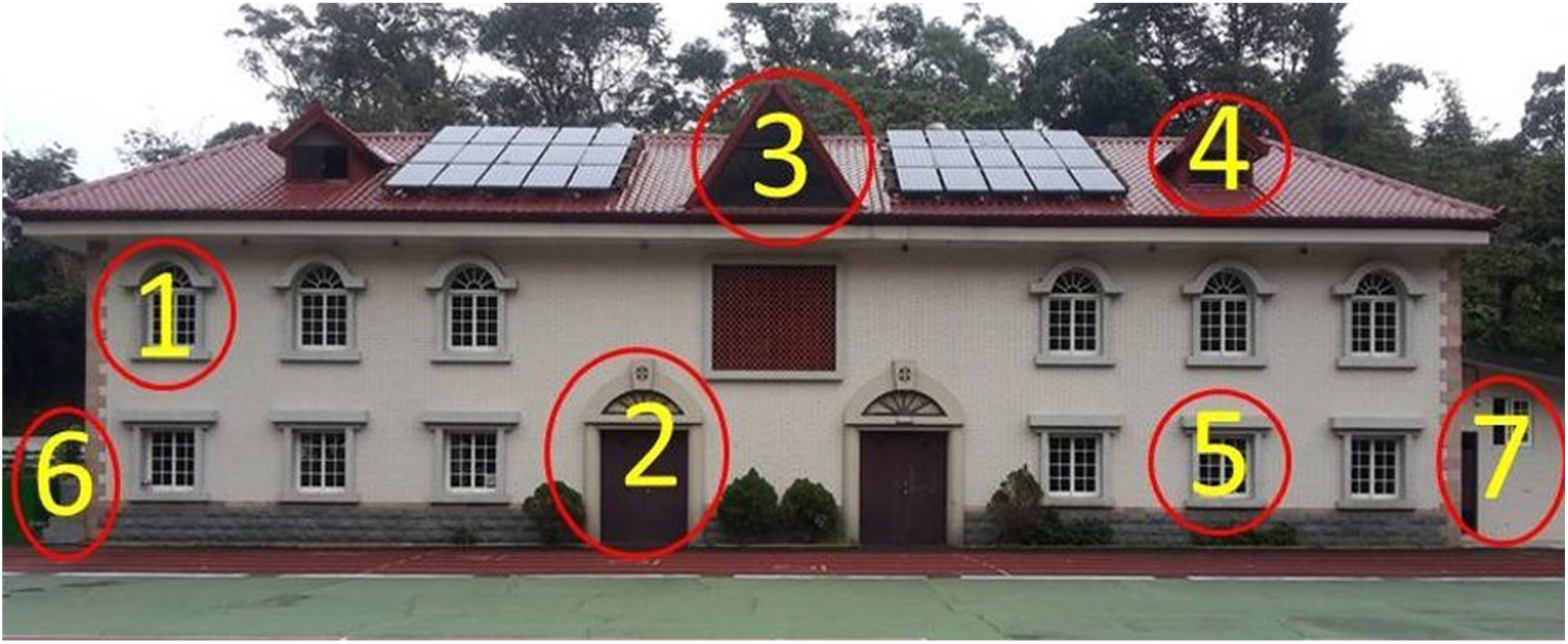
Photograph of gymnasium.
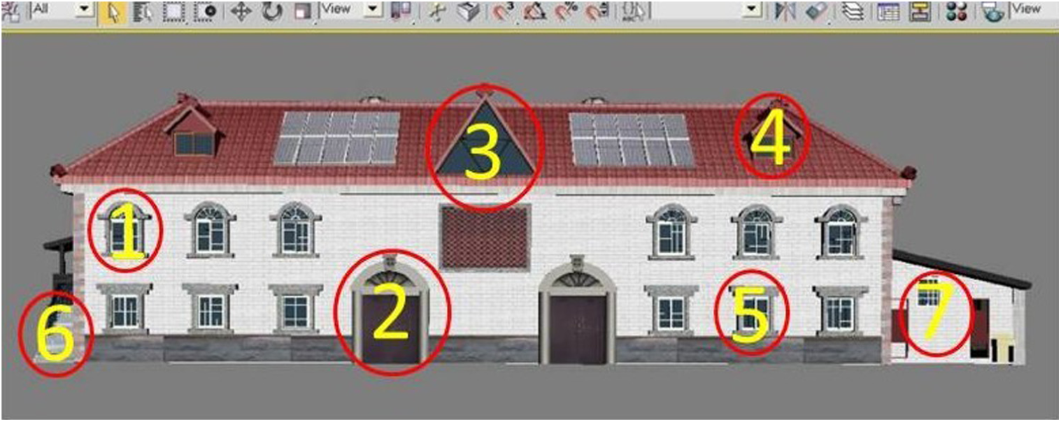
Model of gymnasium.
Number 1: top row of windows
Making a model of window was difficult because its pane was located inside arc; first, the two-dimensional (2D) lines are drawn and then the Extrude function is used to extrude the window frame. See Figure 9.

Comparison between the real window and the model.
Number 2: curved arches
The look and the shape of arches are similar to the window arches, and we used the pattern to complete this model. See Figure 10.

Comparison between the arc and its model.
Number 3: triangle window on the roof
The most challenging part of making the model involved the ridge of the roof, as it was not regular. Therefore, a 2D drawing was made, and then the Extrusion tool was used to make a 3D model. The rest of the work involved simply drawing a window frame. See Figure 11.

Comparison between the triangle window and its model.
Number 4: transom windows
The roof cannot be seen from the ground. Therefore, in modeling the roof, some of the details were imagined. The most difficult part was to arrange the tiles, as some of the tiles were placed under 90 degree angle to the others, and we had to copy and paste multiple times to finish the model. See Figure 12.

Transom window and its model.
Number 5: bottom row of windows
Modeling was similar to the top row of windows. Some of the elements of the top row of windows were used for the bottom row. See Figure 13.

Bottom row of windows and its model.
Number 6: left wall of gymnasium
As the terrain by the left wall of the gymnasium was not even, all of the visible sights were drawn. The terrain was edited using the Unity3d editing tools. See Figure 14.

Left wall of the gymnasium and its model.
Number 7: restroom of gymnasium
As only the exteriors of the buildings were modeled, the inside of the modeled restroom was empty, but all of the attributes that were visible from the outside were present, including the air conditioner and the sinks. See Figure 15 for a comparison between the restroom and its model.

Restroom and its model.
Construction of Unity3d scene
When the 3D model has been created, it is imported to Unity3d. The Unity3d landscape architecture (Terrains) and Standard Assets, located in the Asset Store, and other related models can be used to complete the design of the campus scene by adjusting the asset properties.
Model of scenery around campus
During this project, multiple models of various features of campus were created, including the buildings, the sign on the campus gate, the basketball court, traffic lights, guard booths, lighted signs, electric gates, arch bridges, searchlights, ponds, and others. See Figure 16.

Rong’Hua building and its model.
The Fuhua building can be seen from the main gate. On the right of the campus is a large Chinese science and technology building, called the Fuhua building. The architecture of the building is unique, as it utilizes inclined window panes. In modeling this building, all of the windowsills had to be separated, and the building was divided into blocks. After the windowsills were drawn, similar building blocks were created to complete the model. Since no drones were used to record video of the campus, and the photographs that were taken from the ground provided all available pictorial information, photo editing software was used to make the final model. See Figures 17–19.
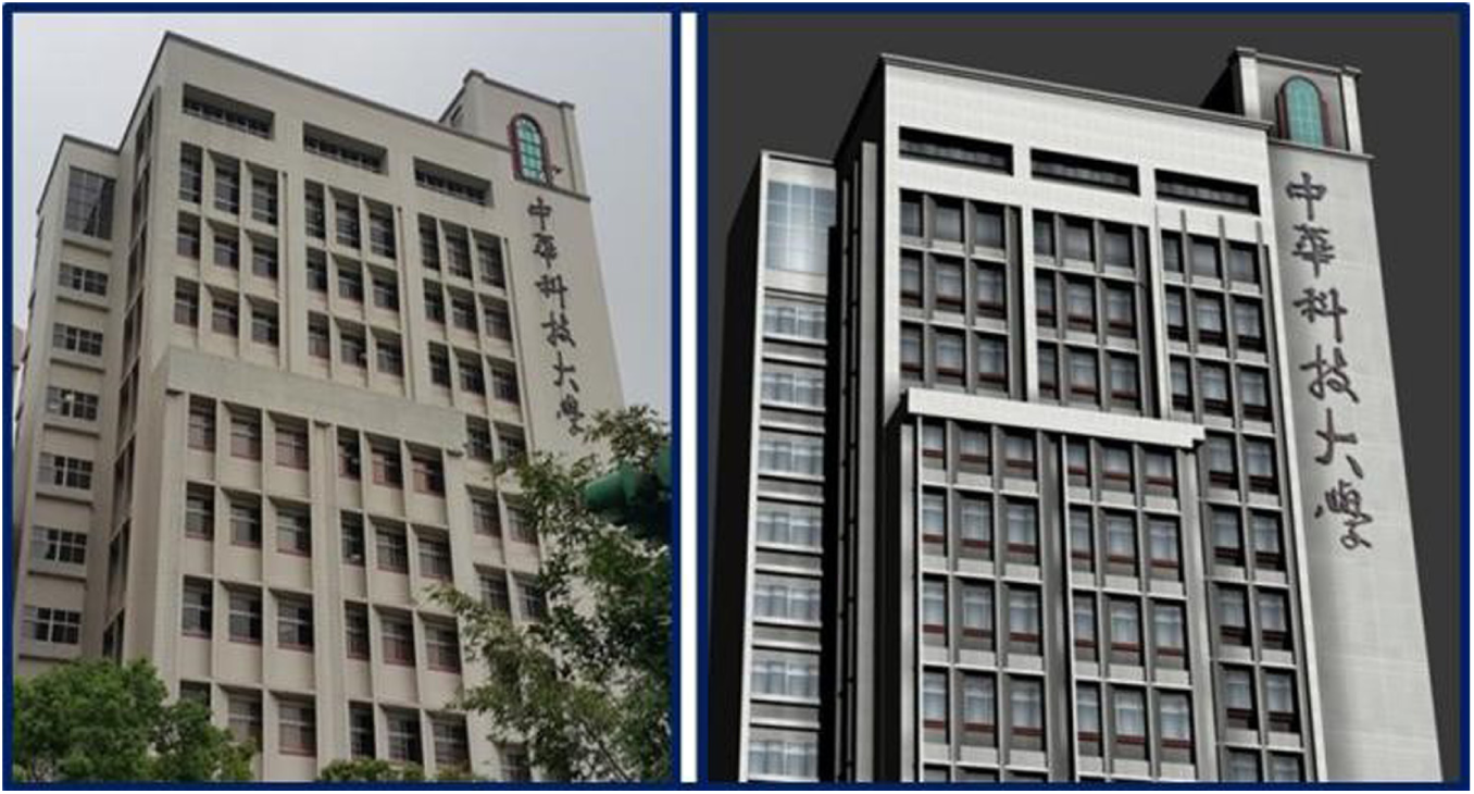
Fuhua building and its model.
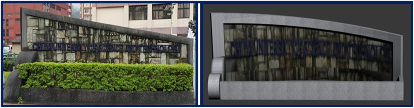
Sign on campus gate and its model.

School gate and its model.
Test of VR operation
The operation of the VR platform was tested in two parts. In the first, the VR scene display was tested, and in the second the action simulation was tested. The VR scene display test was performed primarily to demonstrate the completeness of the scene, and the action simulation test was performed to show the connection interaction between the wearable device and the VR scene.
VR scene display test
First, the aerial photograph of the campus was compared with the virtual models using seven locations, as shown in Figures 20 and 21.

Aerial photograph of campus.

Virtual reality scene.
Figure 22 shows all of the surroundings.
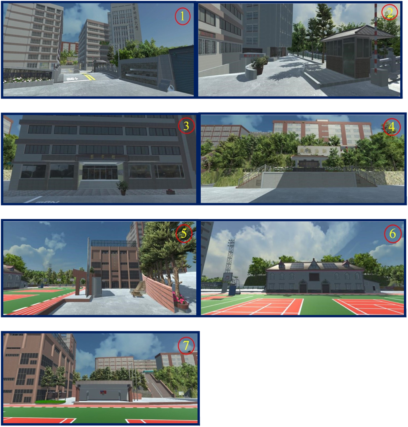
1. Campus gate and surroundings; 2. Guard room and surroundings; 3. Library; 4. Memorial gate and surroundings;5. Students’ Activity Center and surroundings; 6. Gymnasium and surroundings; 7. Command desk and surroundings.
Action simulation test
The action simulation test was performed to check that the scene changes are consistent with the movements of the user. The user wore the wearable device and performed certain actions: as he turned his head to the left or to the right, raised it, or lowered it, the virtual scene changes were observed for consistency with the movement of the user (Figures 23–25).

Testing the main entrance of the campus: 1. User is not moving his head, but looks to the front; 2. User turns his head 30 degrees to the left, observing the scenery; 3. User turns his head 30 degrees to the right, observing the scenery; 4. User raises his head at 30 degree angle, observing the scenery; 5. Looking down at 30 degrees, observing whether the scenery has started moving.

Jingcheng building test: 1. User is not moving his head, but looks to the front; 2. Turning the head 30 degrees to the left, observing the scenery; 3. User turns his head 30 degrees to the right, observing the scenery; 4. User raises his head 30 degrees, observing the scenery; 5. User looks down at 30 degrees, observing whether the scenery has started moving.

Stadium test: 1. User does not move his head, but looks to the front; 2. User turns his head 30 degrees to the left and observes the scenery; 3. User turns his head 30 degrees to the right, observing the scenery; 4. User raises his head at 30 degrees, observing the scenery; 5. User looks down at 30 degrees, observing whether the scenery has started moving.
Conclusion
As Internet technology is already well developed, search engines make huge amounts of information publicly available excluding confidential or secret materials. In the future, if necessary, the geometric VR platform will be used as a separate navigation application, published on school website. It will allow people to obtain information about the campus environment. By simply downloading the application and using the easy-to-use Google Cardboard, which is commercially available, one can virtually visit the campus using only his or her phone. The Geometric Virtual Reality project, from conception to completion, was a long exploratory process. 3D models of the buildings on campus were constructed to make them as similar to the buildings as possible.
In the circuit design, a somatosensory detection transmission board was used to detect the user’s movements, and signals from the transmission board were sent through a Bluetooth Master terminal. With the help of the wireless Bluetooth signal receiving board, the signals were converted to the RS232 level and transmitted using universal asynchronous receiver–transmitter (UART) serial transmission to the Unity3d VR. We tested different movements and the results of the tests were positive. In addition, regarding the school features, information about school’s territory, or any other detailed information, can be added to the VR interactive platform, to make the navigation platform more lively and interesting.
Footnotes
Handling Editor: Stephen D Prior
Declaration of conflicting interests
The author(s) declared no potential conflicts of interest with respect to the research, authorship, and/or publication of this article.
Funding
The author(s) disclosed receipt of the following financial support for the research, authorship, and/or publication of this article: The authors would like to thank the Ministry of Science and Technology of Taiwan, R.O.C., for financially supporting this research under Contract No. MOST 106-2622-E-197-010-CC3.