
Abstract
In practical engineering, the choice of blade shape is crucial in the design process of turbine. It is because not only the structural stability but also the aerodynamic performance of turbine depends on the shape of blades. Generally, the design of blades is a typical multidisciplinary design optimization problem which includes many different disciplines. In this study, a fluid–structure coupling analysis approach is proposed to show the application of multidisciplinary design optimization in engineering. Furthermore, a strategy of uncertainty-based multidisciplinary design optimization using fluid–structure coupling analysis is proposed to enhance the reliability and safety of blades in turbine. The design of experiment technique is also introduced to construct response surface during uncertainty-based multidisciplinary design optimization using fluid–structure coupling analysis. The design solution shows that the adiabatic efficiency is increased and the equivalent stress is decreased, which means that better performance of the turbine can be obtained.
Keywords
Introduction
In modern industry, the design approaches of turbine or compressor blades have gained more and more attention.1–5 Blades usually are machined and formed in different shapes according to the required performance of compressors or turbines. Generally, there are complex three-dimensional (3D) flow fields in turbines or compressors. It is because of the existence of boundary layer separation, downstream wake flow field, and secondary flow.6–9 Consequently, the interaction analysis of the shockwave and boundary layer is important for the structural design of shapes.10,11 A lot of research has been done in this field through numerical and experimental studies. In practical engineering, however, it is not usually easy to simulate the performance by the experiments only. To solve this problem, the fluid–structure multidisciplinary analysis (FSMA) has been introduced into engineering applications.12–17 Jenkins and Maute proposed an immersed boundary approach. This approach can change the fluid–structure interface during the design process. 12 Suryawanshi and Ghosh 13 considered two aeroelastic stability problems, divergence, and flutter, in reliability-based design optimization of compressor shapes. They also created a polynomial chaos expansion (PCE)-based metamodel to reduce the computational cost during the optimization process. Stander et al. 14 considered fluid–thermal–structure interaction problems and constructed high-fidelity models of three disciplines. A monolithic multidisciplinary feasible architecture is introduced to solve the above multidisciplinary design optimization (MDO) problem. Nikbay and Acar 16 applied reduced order modeling techniques to predict the aeroelastic performance of wine. They analyzed the fluid structure interaction from a finite element solver and a 3D Euler unsteady aerodynamic solver by the structural modal solution.
In this study, the uncertainty-based multidisciplinary design optimization (UBMDO) of blades is solved. The performance including adiabatic efficiency and total pressure ratio of the blades is considered here. The aerodynamic performance and reliability of the structure will be optimized in the updated model of blades. The rest of this study is organized as follows. In section “Numerical analysis of blades,” the numerical analysis of blades will be discussed. The model of the reference blade, the meshing methods, and the theoretical analysis basis will also be presented in detail. The design of experiment (DOE) technique will be introduced in section “The DOE and response surface method.” The central composite design (CCD) is applied in the design and optimization process to enhance the calculation efficiency. In section “The optimization model and the design solutions,” the collaborative optimization (CO) method will be combined with the method proposed above and utilized to solve a specific UBMDO problem of the blade. The conclusions will be presented in section “Conclusion.”
Numerical analysis of blades
The design model and variables of blades
Generally, blades should be manufactured using an approach which can connect the blades to the turbine or compressor securely. In this study, the blades investigated belong to a particular type of centrifugal compressor. This centrifugal compressor has 15 blades which are shown in Figure 1. The SolidWorks software is utilized here to build up the simulation model of a blade.
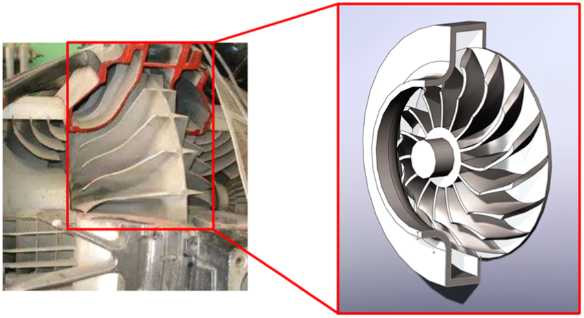
The model of blade in a centrifugal compressor.
As shown in Figure 2, the design information is given by introducing the key points at different layers of the blade. All key points are treated as the design variables.
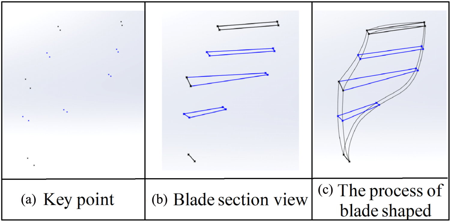
The design key point of the blades: (a) key point, (b) blade section view, and (c) the process of blade shaping.
The meshing methods and their application in the blade model
There are three types of meshes: standard mesh, curvature-based mesh, and blended curvature–based mesh, which can be generated by the SolidWorks software and are usually utilized in the fluid analysis of blades. In this study, the pressure ratio and the adiabatic efficiency of the blades are considered. The standard is utilized as the structural domain here. The variation of the number of grid elements is from 400,000 to 2,000,000. Furthermore, the number of grid elements is set at 700,000 because the solutions are almost uniform over 700,000. Generally, the number of grid elements can be varied from 70,000 to 170,000 in the case of structural and dynamic analyses.18–23 Consequently, the mesh number is set at 130,000 from the solution which is uniform over 130,000 mesh elements (Figure 3).
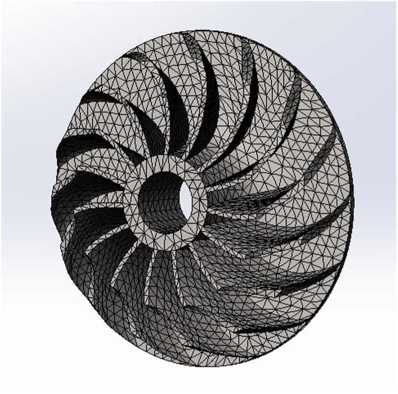
Meshing in blades.
FSMA
Here, the working fluid around the blades is treated as ideal air to perform the steady-state computational fluid dynamics (CFD) analysis. The 3D Navier–Stokes equations are introduced to the analysis of the flow filed passing through the blades on turbine. In this study, the pressure and temperature at the inlet can be set at 294.24 K and 151,365 Pa, respectively. The
Boundary condition information in this case.

The performance of centrifugal compressor can be evaluated by the adiabatic efficiency, equivalent stress, and total pressure ratio.
24
In this study, to ensure structural safety, we set minimizing the equivalent stress on the blade surface as the objective during the optimization. The adiabatic efficiency

and the efficiency is defined as 24

where
The pressure ratio and adiabatic efficiency.

CFD: computational fluid dynamics.
In order to conduct the fluid–structure coupling analysis (FSCA), the hub of the rotor was fixed. The pressure obtained from the CFD results can be utilized on the blade surfaces, which is shown in Figure 4.

The FSCA for the rotor in centrifugal compressor.
Results of the reference model
First, we analyzed the aerodynamic performance parameters of the centrifugal compressor. Considering the equivalent stress of the rotor, the total

Velocity distribution of the reference model.
Then, we introduced the pressure of air to perform the one-way CFD analysis of the blade, which is illustrated in Figures 6 and 7. We can find that the maximum stress applied on the blade surfaces of the rotor and the total displacement were about 31.8 MPa and 2.45 mm, respectively. The maximum stress of the rotor is focused at the root of the blade. The total displacement is focused at the top of the blade.

Von Mises stress distributions of the blade.
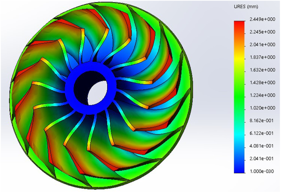
Displacement of the blade.
The DOE and response surface method
Curve-fitting techniques have been applied to derive the functional relationships between the independent and dependent variables. Researchers can obtain the relationship between the design variables and performance prediction based on the experimental data. In order to speed up the evaluation of design performance, the iSIGHT software is used to construct alternative approximation models in this study. This is a simulation software that performs based on a variety of approximation principles. Furthermore, to improve the efficiency of the analysis task, the iSIGHT approximation model can also be used to eliminate the calculation noise from the simulation software. The calculation noise fluctuates sharply from the input parameter but oscillates the output parameter. The calculated noise produces numerous local peaks that can have a significant negative impact on the optimization process. Approximation models often naturally smooth the response function, thus improving the convergence of the optimization process in most cases.
In this study, the optimization approaches based on the approximation have been adapted to compressor blade optimization. The utilization of these design approaches can reduce the cost of optimization effectively. As shown in equation (3), various design parameters are chosen using CCD for optimization

where

The DOE process in iSIGHT.
The response surface method (RSM) is a statistical mathematical method which can evaluate the effect of input information on the objective function. The nonparametric regression approach is introduced in this study to evaluate the involved design information. It is helpful to construct a surrogate model which is closer to the original information relatively. The accuracy and effectiveness of the response surface model can also be checked by the appropriateness test in equation (4)

where
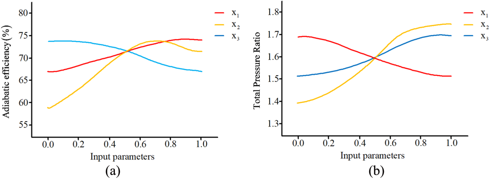
The solutions of sensitivity with input variables: (a) adiabatic efficiency and (b) total pressure ratio.
The optimization model and the design solutions
During the optimization process, the objective can be set to optimize the equivalent stress on the blades of the rotor. Here, the constraints are set as certain values of the equivalent stress, adiabatic efficiency, and total pressure ratio and of the blades. The conditions for optimization are as follows
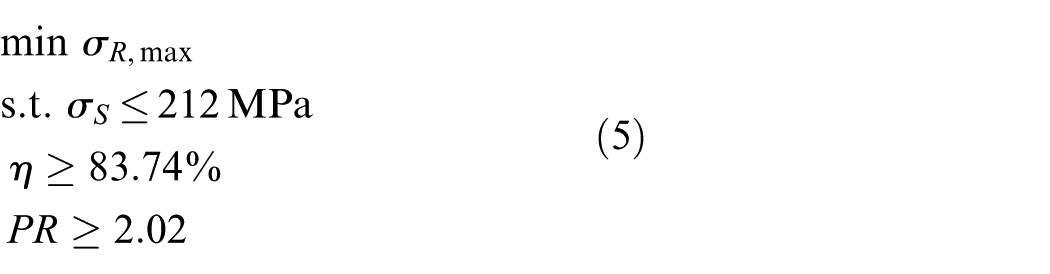
where the subscript max means the maximum equivalent stress. The purpose of this optimization problem is to enhance the reliability of the compressor while keeping the current performance.
Here, the comparison of design solutions obtained by RSM and CFD is shown in Table 3. For each of the output parameters, the relative error is 0.5% about the pressure on the rotor, 0.68% about the stress on the stator, 0.04% for the total pressure ratio, and 0.4% for the efficiency. The solutions of the reference model and the optimized model are given in Table 3. We can find that the total pressure ratio remains at the current level. However, the adiabatic efficiency was increased by 2.7%, while the maximum equivalent stress is decreased by 4%.
The comparison of results from RSM and CFD.

RSM: response surface method; CFD: computational fluid dynamics.
Conclusion
In this study, an MDO problem of the blade used in a centrifugal compressor is introduced to illustrate the application of the proposed method. The CFD solutions of the reference model are compared with the experimental solutions. The FSCA is performed based on the stress from the CFD results. Then, the shape optimization problem of blades is solved by utilizing the surrogate model. The solutions are obtained including the adiabatic efficiency, equivalent stress and total pressure ratio. The structural safety is increased, while the total pressure ratio remained at the current level.
Footnotes
Handling Editor: Hamid Reza Karimi
Declaration of conflicting interests
The author(s) declared no potential conflicts of interest with respect to the research, authorship, and/or publication of this article.
Funding
The author(s) disclosed receipt of the following financial support for the research, authorship, and/or publication of this article: The support from the National Natural Science Foundation of China (Grant No. 51605080) and the China Postdoctoral Science Foundation (Grant Nos 2015M580780 and 2017T100685) is gratefully acknowledged.