
Abstract
To improve the product quality of self-lubricating spherical plain bearing, a new shape of the outer rings for spherical plain bearings was optimally designed based on virtual orthogonal experiments using finite element software ABAQUS. The depth inclined end wall, together with the length of annular wall, the depth of annular concavity, the outer ring thickness, and the edge radius were taken as the main structural parameters in the analysis. For the evaluation parameters, the maximum bearing clearance, the maximum contact pressure, the maximum extrusion load, and the maximum equivalent plastic strain were considered. The optimal structure parameter combination was identified based on the intuitive comprehensive balance analysis method. The simulation results demonstrated much improvement for the forming quality by using a new type of the outer ring, which was optimized by the virtual orthogonal experiments. The new type of the outer ring could be used to the forming process in assembling the spherical plain bearings.
Introduction
The self-lubricating spherical plain bearing consists of inner ring, outer ring, and self-lubricating composite liner. It is widely used in aerospace, military machinery, and water conservancy facilities because of its advantages of simple structure, small size, low friction coefficient, higher bearing capacity, and higher wear resistance.1–4 The bearing must be engineered precisely due to the cold forming process. Finite element analysis is a good approach to predict the amount of deformation, contact stresses, and stress and strain distribution for the large deformation problem. In order to provide effective guidance for the selection of forming process parameters, 5 some researchers have studied on spherical plain bearings. Wu and Yang 6 has studied on extrusion process parameters optimization of the die cavity with ABAQUS and experiments. The press forming of outer ring in a typical spherical plain bearing has been investigated using a finite element model (FEM), and it provides theoretical guides for enhancing performance of the spherical plain bearings and improving the shape of the outer ring blank or the die design. 7 The forming load analytical equations for various process parameters were proposed by a plane strain analysis considering the existence of a rigid end. 8 An artificial neural network was combined with genetic algorithm to optimize the extrusion die cavity. 9 The maximum compressive stress under the different ball diameter of spherical plain bearing was analyzed by Wang and Wang. 10 Moreover, the validity of forming load predictions was examined through a comparison with experiment and FEM by Orsolini and Booker. 11 Aguirrebeitia et al. 12 presented a model to assess the equivalent load for self-lubricating radial spherical plain bearings under combined loads, based on the study of the interference field. However, few scholars have engaged in the optimization of outer rings of spherical plain bearings to improve the product quality. In this work, spherical plain bearing with a new outer ring was proposed, and the dimension parameters were optimized by virtual orthogonal experiments under the numerical simulation of nosing process and spring back process.
FEM for forming process
Modeling data
In this work, a typical spherical plain bearing, as shown in Figure 1, is chosen. The material properties are shown in Table 1. In order to describe the plastic deformation of the extrusion process, the stress–strain behavior of 0Cr17Ni4Cu4Nb is obtained by the standard uniaxial tensile test. To simplify the model of polytetrafluoroethylene (PTFE) fabric liner, the stress–strain behavior is obtained by compression test in thickness direction because the main deformation is considered in thickness direction during extrusion process. The stress–strain curves are shown in Figure 2.

Schematic diagram of the spherical plain bearing.
Material properties of the spherical plain bearing.
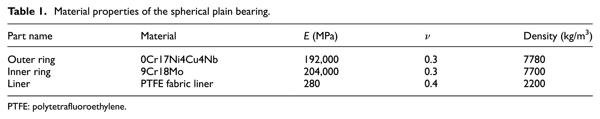
PTFE: polytetrafluoroethylene.
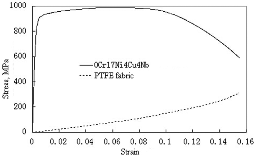
Stress–strain curves of 0Cr17Ni4Cu4Nb and PTFE fabric liner.
The FEM
The FEM is established according to a spherical plain bearing manufacturer (FJLX Bearing). Schematic of the nosing process is shown in Figure 3. ABAQUS explicit is used to analyze the axisymmetric model of the bearing. The lower die is fixed, and the upper die and the upper and lower positioning sleeves are moved downward simultaneously, which are defined as analytic rigid body to reduce the CPU time. 11 The outer ring, the inner ring, and the liner are all considered as deformable bodies, and they are meshed using the CAX4R element (a four-node bilinear axisymmetric quadrilateral element with enhance hourglass control) via free mesh method. The reasons for using this element are as follows: (1) the established model is an axisymmetric one and therefore an axisymmetric element is used; (2) the material property of the established model can be described by bilinear one which has been validated by the authors of this article; 13 (3) the quadrilateral element can meet the precision requirement in the plane simulation. It is noted here that the accuracy and reliability of the FEM for the extrusion assembly process for GEW12DEM1T spherical plain bearings has been validated by the authors of the paper via comparing the simulated and experimental results. 14 There are only simulated results presented in this work. In addition, the model is for quasi-static analysis, 13 and therefore, the effect of inertia force could be neglected. In the real manufacturing, the extrusion speed is slow, so the temperature due to the friction and deformation changes slightly, and the effect on the stress change is very small. Therefore, the temperature is not taken into account in this work.

Schematic of the nosing process: (1) upper positioning sleeve; (2) inner ring; (3) lower positioning sleeve; (4) lower die; (5) PTFE fabric liner; (6) outer ring blank; (7) upper die.
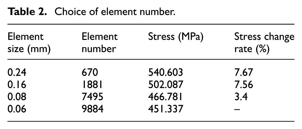
Here, the effect of element size on the established model has been investigated. Normally, models with smaller elements will get better computational precision, but it will take more time to compute. As shown in Table 2, if the element size is 0.08 mm, the stress change rate is only 3.4% which is compared with the stress using the element size of 0.06 mm. To achieve faster computation with approximate precision FE result, the number of the elements and nodes are 7495 and 7876, respectively.
Choice of element number.
The friction coefficient between the die and the inner ring and the one between the inner ring and the outer ring are both set to 0.15. 11 Meanwhile, the friction coefficient between the liner and the inner ring is set to 0.04. 15 To improve computational efficiency, the upper die is moved downward vertically at a velocity of 40 mm/s which is considered to be a quasi-static process, 16 and the total displacement of the upper die is set to 6 mm. To obtain accurate deformation shapes for the assembling process, the spring back analysis is performed by removing the dies and positioning sleeves after extrusion process.
Optimization of the outer ring of spherical plain bearings
The orthogonal experiment model
The quality of spherical plain bearings is directly affected by the shape of the outer ring. The simulation results showed that the bearing clearance is not uniform, and the contact pressure on the liner surface and the extrusion pressure are too large when the original bearing outer ring was conducted into the extrusion assembling process. Aiming at these problems, a new type of the bearing outer ring blank was proposed. The schematic diagram of the original and the new type outer ring blanks are shown in Figure 4. As shown in Figure 4, the orthogonal experiment model of bearing outer ring blank is different from the original one. The shape of the new one is now with some curved surfaces which will finally affect the quality of spherical plain bearings. In the model, the inner radius of the outer ring Dk/2 and the width of the bearing outer ring C are unchanged. However, the new type of bearing outer ring blank involves five parameters: the depth of inclined end walls a, the length of annular walls b, the depth of an annular concavity c, the thickness of outer ring blank e, and the radius of edges r. The optimization procedure is to determine these parameters. First, ones will determine the parameter a, the other parameters are unchanged. For example, the parameters a can be set between 0.5 and 0.8 mm. For an incremental step of 0.1 mm for parameter a, new FEMs will be built to analyze the structures. Similarly, for the parameter e, it can be set between 2.8 and 2.95 mm with an incremental step of 0.05 mm; also, the parameter b could be set as 0.7 and 1.0 mm with an incremental step of 0.1 mm. Therefore, finite element analysis of a series of bearing outer ring blank with different parameters will achieve its optimal design.
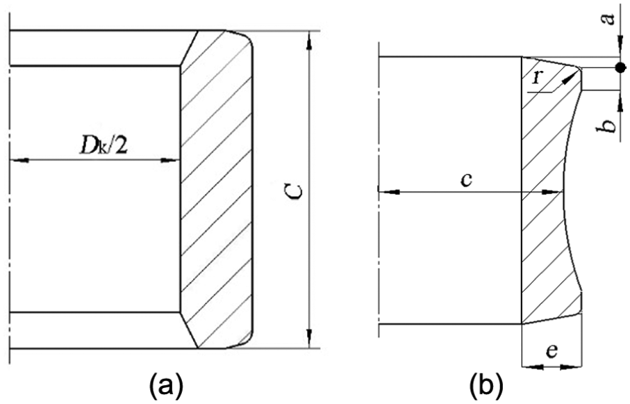
Schematic of the bearing outer ring blank: Dk/2 is the inner radius of the outer ring blank; C is the width of the bearing outer ring; a is the depth of inclined end walls; b is the length of annular walls; c is the depth of an annular concavity; e is the thickness of outer ring blank; r is the radius of edges. (a) original outer ring blank and (b) new type outer ring blank.
After a great number of simulation and analysis, the ranges of five dimension (5D) parameters as the experiment factors have been determined. The four-level orthogonal array L16(45) is employed 17 as it is shown in Table 3. Meanwhile, the maximum radial clearance (Grmax), the maximum contact pressure (Pmax), the maximum extrusion pressure (Fmax), and the maximum equivalent plastic strain (δmax) are taken as the evaluation parameters to ensure the quality of the assemble process.
Experiment parameters with their range and values.

The results of orthogonal experiment
The detailed scheme of orthogonal experiment and numerical simulation results are listed in Table 4, in which k is the average value of each factor’s level; R is the range of the results, which reflect the important degree of various factors.
Orthogonal table and numerical simulation results.
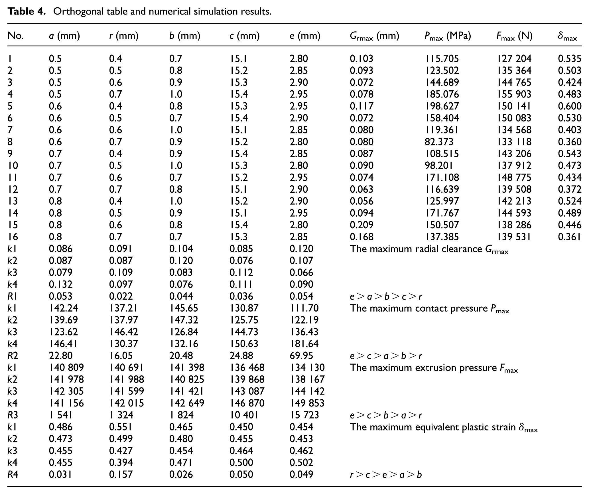
The minimum radial clearance Grmax has shown in the 13th group. The value is 0.056 mm which is within the range of allowance. Meanwhile, other evaluation parameters are better than the original results. The dimension parameter combination is a4r1b4c2e3. However, this is not the best combination. In order to get an optimal combination, the results are analyzed based on the values given in Table 4 as follows:
According to the range R1, the order of effective extent of each factor parameter to the maximum bearing clearance Grmax is: e > a > b > c > r.
According to the range R2, the order of effective extent of each factor parameter to the maximum contact pressure Pmax is: e > c > a > b > r.
According to the range R3, the order of effective extent of each factor parameter to the maximum extrusion pressure Fmax is: e > c > b > a > r.
According to the range R4, the order of effective extent of each factor parameter to the maximum equivalent plastic strain δmax is: r > c > e > a > b.
Influence of dimension parameters on Grmax.
According to the range R1, the three most significant dimension parameters which influence the maximum radial clearance Grmax are the thickness of the outer ring e, the depth of inclined end walls a, and the length of annular walls b. Figure 5(a) shows the variation of the maximum radial clearance with the thickness of the outer ring. The maximum radial clearance decreases when the thickness of the outer ring is lower than 2.9 mm. However, it increases when the thickness of the outer ring is higher than 2.9 mm. Figure 5(b) shows the effect of the depth of inclined end walls on the maximum radial clearance. The maximum radial clearances slowly increase when the depth of inclined end walls is lower than 0.6 mm. Subsequently, it slowly decreases when the depth of inclined end walls is between 0.6 and 0.7 mm. The maximum radial clearance increases sharply when the depth of inclined end walls is higher than 0.7 mm. Figure 5(c) shows that the variation of the maximum radial clearance with the length of annular walls. It is observed that the length of annular walls at 0.8 mm is an inflection point. The maximum radial clearance increases when the length of annular walls is lower than 0.8 mm. Subsequently, it decreases when the length of annular walls is higher than 0.8 mm.
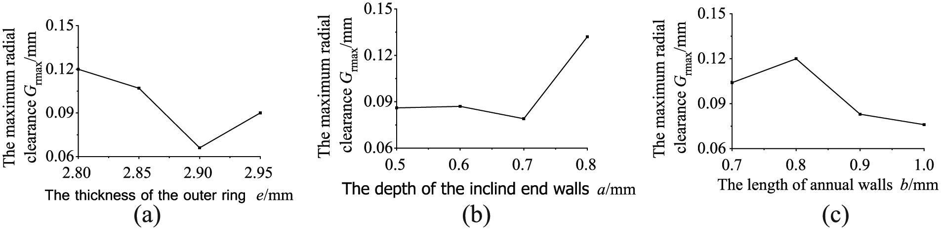
The variation of Grmax with four levels of main effective dimensions: (a) the thickness of the outer ring; (b) the depth of the inclined end walls; (c) the length of annual walls.
Influence of dimension parameters on Pmax.
To the range R2, the three most significant dimension parameters which influence the maximum contact pressure Pmax are the thickness of the outer ring e, the annular concavity c and the depth of inclined end walls a. Figure 6(a) shows the variation of the maximum contact pressure with the thickness of the outer ring. With the increase in the thickness of the outer ring, the maximum contact pressure increases at 2.80–2.95 mm. Figure 6(b) shows the effect of the depth of the annular concavity on the maximum contact pressure. With the increase in the depth of the annular concavity, the maximum contact pressure decreases at 15.2 mm. Subsequently, it increases when the depth of the annular concavity is higher than 15.2 mm. Figure 6(c) shows that the variation of the maximum contact pressure with the depth of inclined end walls. It is observed that the depth of inclined end walls at 0.7 mm is an inflection point. The maximum contact pressure decreases when the depth of inclined end walls is lower than 0.7 mm. It increases when the depth of inclined end walls is higher than 0.7 mm.

The variation of Pmax with four levels of main effective dimensions: (a) the thickness of the outer ring, (b) the depth of the annular concavity, and (c) the depth of the inclined end walls.
Influence of dimension parameters on Fmax.
According to the range R3, the three most significant dimension parameters which influence the evaluation parameter of the maximum extrusion pressure Fmax are the thickness of the outer ring e, the annular concavity c, and the length of annular walls b. Figure 7(a) shows the variation of the maximum extrusion pressure with the thickness of the outer ring. With the increasing of the thickness of the outer ring, the maximum extrusion pressure increases at 2.80–2.95 mm. Figure 7(b) shows the effect of the depth of the annular concavity on the maximum extrusion pressure. With the increasing of the depth of the annular concavity, the maximum extrusion pressure increases at 15.1–15.4 mm. Figure 7(c) shows that the variation of the maximum extrusion pressure with the length of annular walls. It is observed that the length of annular walls at 0.8 mm is an inflection point. The maximum extrusion pressure decreases when the length of annular walls is lower than 0.8 mm. Subsequently, it increases when the length of annular walls is higher than 0.8 mm.

The variation of Fmax with four levels of main effective dimensions: (a) the thickness of the outer ring, (b) the depth of the annular concavity, and (c) the length of annual walls.
Influence of dimension parameters on δmax.
According to the range R4, the three most significant dimension parameters which influence the evaluation parameter of the maximum equivalent plastic strain δmax are the radius of edges r, the depth of inclined end walls c, and the thickness of the outer ring e. Figure 8(a) shows the variation of the maximum equivalent plastic strain with the radius of edges. With the increase in the radius of edges, the maximum equivalent plastic strain decreases at 0.4–0.7 mm. Figure 8(b) shows the effect of the depth of inclined end walls on the maximum equivalent plastic strain. With the increasing of the depth of the annular concavity, the maximum equivalent plastic strain increases at 15.1–15.4 mm. Figure 8(c) shows that the variation of the maximum equivalent plastic strain with the thickness of the outer ring. With the increasing of the thickness of the outer ring, the maximum equivalent plastic strain increases at 2.80–2.95 mm.

The variation of δmax with four levels of main effective dimensions: (a) the radius of edges, (b) the depth of the annular concavity, and (c) the thickness of the outer ring.
The intuitive analysis of the integrated balance method
To ensure the quality of spherical plain bearings, each of the evaluation parameter must be the minimum. According to the minimum k of each dimension parameter, the optimal dimension parameters combination of each evaluation parameter is shown in Table 5.
The optimal dimension parameters combination of each evaluation parameter.

Because of the disagreement of four optimal combinations, the effect degree of each dimension parameter needs to be considered when determining the optimal combination. The depth of inclined end walls a has a large impact on the maximum radial clearance Grmax ranked second. It has an impact on the other evaluation parameters ranked third or fourth. Level 3 of the depth of inclined end walls enables to guarantee the minimum value of Grmax, Pmax, and δmax. The optimize effect is better than level 1 hence, the level 3 is selected. The radius of edges r has the largest impact on the maximum equivalent plastic strain δmax ranked the first. It has a minimum impact on the other evaluation parameters. The level 4 ensures the minimum value of δmax, so the level 4 is chosen. The length of annular walls b has a large impact on the maximum radial clearance Grmax and the maximum extrusion pressure Fmax ranked second, respectively. It has a little impact on the other evaluation parameters ranked fourth or fifth. The optimized effect of the level 4 is better than the level 2 for reducing bearing radial clearance. So the level 4 is selected. The depth of an annular concavity c has a large impact on the maximum contact pressure Pmax and the maximum extrusion pressure Fmax ranked third, respectively. It has an impact on the maximum radial clearance Grmax ranked the fourth. Compared to level 1, level 2 reduces the bearing radial clearance and the liner contact pressure more effectively, so the level 2 is selected. The thickness of outer ring blank e has the largest impact on the maximum radial clearance Grmax, and the maximum contact pressure Pmax and the maximum extrusion pressure Fmax ranked the first, respectively. It has an impact on the minimum value of δmax ranked third because level 3 has carried out the minimum bearing radial clearance. However, the increment of the liner contact pressure is not too big than level 1 and level 2, so level 3 is selected. In summary, the optimal combination of dimension parameters is a3r3b4c2e3 as follows: a = 0.7 mm, r = 0.7 mm, b = 1 mm, c = 15.2 mm, and e = 2.9 mm.
The comparison of the optimization results
The results are compared with the original bearing, and the von Mises stress distribution diagram are shown in Figure 9. Obviously, the new bearing outer ring has a flat surface. Moreover, the stress concentration area in the bearing inner ring has disappeared. The highest stress area of the bearing outer ring is effectively reduced. The residual stress of the spherical plain bearing is effectively reduced as well. For example, as shown in Figure 9, the maximum von Mises stresses of the inner rings before and after the optimization are 222.5 and 79.02 MPa, respectively. Therefore, the maximum von Mises stress of the inner ring decreases by 64.5% after the optimization. Similarly, the maximum von Mises stresses of the PTFE liner and outer ring decrease by 68.6% and 0.69%, respectively after the optimization.

The von Mises stress distribution diagram after spring back process: (a) spherical plain bearing with original inner ring; (b) spherical plain bearing with new inner ring; (c) spherical plain bearing with original PTFE liner; (d) spherical plain bearing with new PTFE liner; (e) spherical plain bearing with original outer ring; and (f) spherical plain bearing with new outer ring.
Figure 10 shows the equivalent plastic strain distribution after extrusion process. The highest equivalent plastic strain area of the outer ring is decreased. Specifically, the maximum value reduces 0.35e–1 after optimization. The maximum equivalent plastic strain area of the liner is also reduced, but some equivalent plastic strain still exit at the end of the liner. Because the bearing clearance needs to be compensated when the bearing outer ring is spring back after extrusion process.

The equivalent plastic strain distribution diagram after extrusion process: (a) spherical plain bearing with original outer ring blank and (b) spherical plain bearing with new type outer ring blank.
The curves of contact pressure along the path before and after optimization are shown in Figure 11. The path is set along the liner face. Compared with the original result that the liner contact pressure has decreased significantly and the changing trend of the curve has been slowed down. The maximum contact pressure occurs at 1.1 mm from the end of the outer ring, and the maximum contact pressure decreases from 233.61–127.23 MPa after the optimization. It is a decline of 46%, which is far less than the maximum dynamic load 240 MPa of the PTFE fabric liner. In conclusion, the contact pressure is obviously reduced, and the optimized outer ring is protecting the liner from extrusion damage and extending the liner’s service life.

The curves of the contact pressure along the path of the liner before and after optimization.
The time history of extrusion pressure curves for before and after optimization is shown in Figure 12. The extrusion pressure is increased with the increment of the extrusion stroke. Because of the difference of the extrusion stroke in the different outer ring, the extrusion time is different. At the final state of the extrusion process, the extrusion pressure is 0.14 × 10⁶ N after optimization comparing to the original result with a reduction of 22%.

The curves of time history-extrusion pressure of the extrusion process before and after optimization.
The curves of radial clearance along the path of the liner for before and after optimization are given in Figure 13. It is shown that the curve tends to be flat, and the mean value of radial clearance is 0.379 mm after optimization. It is closer to the initial thickness of the liner 0.380 mm comparing to the original result 0.339 mm. The end of the bearing outer ring does not appear obvious excessive extrusion after optimization. The maximum radial clearance is 0.055 mm, which is 21% less than the original result 0.070 mm. Hence, the optimized bearing outer ring improves the bearing quality.

The curves of the radial clearance along the path of the spring back process before and after optimization.
In practical measurement of bearing radial clearance, the spherical plain bearing needs to be cut into two parts. According to the standard SAE AS81819, five assigned points t1–t5 on the specific edge in Figure 14 will be measured by a vernier caliper. In this article, the simulation results of radial clearance are measured by the finite element software ABAQUS. The results are given in Table 6.

Schematic diagram of bearing radial clearance test (not in scale).
Radial clearance results of t1–t5.

The fluctuation value of radial clearance is obviously declined by 76% after optimization, which meets the AS81819 SAE standard: the bearing clearance fluctuation value t is less than 0.076 mm, which means the optimized bearing clearance is qualified.
Conclusions
In this work, virtual orthogonal experiments for optimal design of the self-lubrication spherical plain bearings with a new outer ring have been carried out based on the finite element simulation method. The influence of each dimension parameter is analyzed. Subsequently, the dimension parameters that affect the evaluation parameters are revealed. According to the intuitive comprehensive balance analysis, the optimal combination of the bearing outer ring blank is determined. From the analysis results, it is summarized that the radial clearance meets the AS81819 SAE standards; the contact pressure of the PTFE fabric liner and the extrusion pressure is significantly reduced; the equivalent plastic strain of the bearing outer ring is declined; the end of the outer ring surface is smooth and flat to reduce the finish machining allowance and to improve the production efficiency as well. In summary, the spherical plain bearing with new outer ring designed by proposed virtual orthogonal experiments, improves the bearing quality. The new type of the outer ring could be recommended to use to the forming process in assembling the spherical plain bearings.
Footnotes
Handling Editor: Jining Sun
Author’s Note
Shuncong Zhong is also affiliated to School of Mechatronic Engineering and Automation, Shanghai University, Shanghai, China.
Declaration of conflicting interests
The author(s) declared no potential conflicts of interest with respect to the research, authorship, and/or publication of this article.
Funding
The author(s) disclosed receipt of the following financial support for the research, authorship, and/or publication of this article: This research was sponsored by the Fujian Provincial Science and Technology Major Project (2012HZ0006-3), the National Natural Science Foundation of China (11372074, 51675103), the Fujian Provincial Excellent Young Scientist Fund (2014J07007), the State Key Laboratory of Mechanical System and Vibration (MSV-2018-07), and the Shanghai Natural Science Fund (18ZR1414200), Fujian Provincial Natural Science Foundation (2015J01234) and Fujian Provincial Quality and Technical Supervision Bureau Project (FJQI2014008, FJQI2013024).