
Abstract
The poor mobility and complex target motion estimation are the two main challenges in the anti-ship attack missions of high-speed guided missiles. In this study, a new wake-homing scheme of supercavitating vehicles is proposed using the gradient wake flow phenomenon. The basic principle of the wake-homing with laser detection and the information which can be obtained are studied. According to the idiosyncrasy of laser detection, the geometrical characteristics of the vessel wake, and the bubble distribution characteristics, the three-dimensional model of bubble density gradient in horizontal plane of the maneuvering target ship wake flow is first built; the guidance law based on the gradient wake flow is designed and tested. Then, simulation results show the validity of the model wake, the guidance law based on the wake gradient information can accurately track the target. From the simulation results, we also can see that the new wake-homing scheme effectively improve the hit probability, reduce the range of loss, reduce power consumption and gentle guidance trajectory, greatly reduce the mobility requirements of the supercavitating vehicles.
Keywords
Introduction
Due to the fast sailing speed and strong penetration ability, the underwater supercavitating vehicles with the capability of drag reduction have received more and more attention. The water contact parts on the supercavitating body are only the cavitation and the rudder surface. Therefore, losing the most buoyancy is caused by the reduction of the wetted area. 1 For the strong nonlinear effect between the bubble and the body, the inclusion of the supercavitating on the vehicle seriously restricts the maneuverability. 2 The relevant researches on the related technologies of supercavitating vehicles have been carried out in recent years. MD Lin et al. 3 studied the optimal design of conical cavitator for supercavitating vehicles. In Park and Rhee, 4 the two-dimensional cavity shape of a coned cavitation was simulated. In Kim and Kim, 5 the force of supercavitating vehicles in the transition phase was investigated. Li et al. 6 analyzed the fluid dynamic characteristics of the various cone angles. In Mokhtarzadeh et al., 7 the influence of the three different shapes on the stability of vehicle was studied. Li et al. 8 carried out experiments of the time delay effect of the bubble change. In Qiang et al., 9 a state feedback controller was designed using the back stepping method, and the stable control of supercavitating vehicles was realized. R Lv et al. 10 designed an adaptive sliding mode controller based on the guaranteed cost control theory. B Vanek et al. 11 considered the cavitation effect in the calculation of the sliding force of the vehicle and realized the obstacle avoidance tracking using the predictive control method. K Yu et al. 12 used the finite element method to study the interaction between the maneuvering process and the cavity. X Mao and Q Wang 13 achieved the adaptive tracking control of the supercavitating vehicles. JE Dzielski 14 established the nonlinear model of the fully encapsulated supercavitating vehicles and dealt it with the feedback linearization. In Mao and Wang, 15 sliding mode control and linear variable parameter control were used to study the control of supercavitating vehicles. A two-layered framework synthesizing the three-dimensional (3D) guidance law and heuristic fuzzy control was proposed for an underactuated autonomous underwater vehicle (AUV) in Xiang et al. 16 X Xiang et al. 17 presented an application of three major classes of fuzzy logic control about marine robotic vehicles. In order to address the problem of path following for an AUV, C Yu et al. 18 proposed a nonlinear fuzzy controller integrating an improved 3D guidance law. In Xiang et al., 19 a nonlinear controller was mentioned for both fully actuated and underactuated configurations of an AUV. In addition, Ning Wang proposed three different guidance and control schemes which have quite well effectiveness and superiority for an uncertain marine, an underactuated surface vehicle, and an underactuated marine vehicle in Wang et al.20–22 The abovementioned studies have mainly focused on the stability and control of the supercavitating vehicles or on the guidance and control of other marine vehicles. However, there are few works on the guidance methods of the supercavitating vehicles.
The wake is an inherent sign of the moving objects in water, which cannot be thoroughly eliminated and is difficult to be simulated manually.23,24 Wake-homing guidance method has been more and more applied to guide missile hitting vessels for its special characteristics in resistance to temptation and disturbance from enemy. 25 Wake-homing has the ability of finding and guiding missile to follow the moving target based on different detection methods. Laser wake-homing is an emerging non-voice missile homing technology, which uses the laser scattering effect of vessel wakes to guide missile. Laser wake-homing has many advantages such as high anti-interference ability, long impact distance, high hit accuracy, low energy consumption, and good directional attack. Therefore, the research in laser wake-guided technology appears to be very important.
The traditional laser wake-homing estimates whether bubbles exist in the laser path and then distinguishes whether the guided missile enters into or goes through the wake. These could be used as criterions of turning signal sent by guided missile control equipment. In general, there are three trajectories: one regards the wake as axial line, the guided missile sails in snakelike wake, and whether missile goes through the wake boundaries is used as a criterion of turning signal sent by the guided missile control equipment. Another one regards the centerline of wake as axial line, the guided missile sails in snakelike wake, and whether missile approaches the wake boundaries of the vessel is used as the criterion of turning signal sent by the missile control equipment. The last one regards one boundary of the wake as axial line, the guided missile sails in snakelike wake to percept whether missile enters into or goes through the wake of the moving target, which could be used as a criterion of turning signal sent by the guided missile control equipment. As suggested from the above guidance methods, all missiles research falls in snakelike trajectory. But these guidance methods could make the voyage loss increasing greatly for the supercavitating vehicles whose underwater flight speed is high and the maneuvering ability is poor. What is more, the wake range is finite. When the supercavitating vehicle goes through the wake of the moving target, detecting wake of the target will be more difficult for the limits of high speed and poor maneuvering ability, so that the target might disappear. Therefore, an effective scheme is badly needed to solve the guidance problem of the supercavitating vehicles.
In this study, a new wake-homing scheme for supercavitating vehicles is proposed using the gradient wake flow. Without the complicated calculation, the guidance law is only based on the density distribution of wake bubbles. According to the density gradient changing along the axis of wake bubbles, the guidance law was designed to control the angle speed, make the supercavitating vehicles in wake follow the target in the maximum changing direction of bubble density. The simulation results demonstrate that the guidance law could increase the effective loading rate of missile and have a strong applicability for the supercavitating vehicles.
The structure of this article is as follows. Section “Modeling of vessel wake” describes the modeling of vessel wakes. Section “Gradient information model of wake based on laser homing” develops a new gradient information model of wake based on laser homing. Section “Research of the moving target wake in the three dimensions” presents and discusses the moving target wake in the three dimensions. Section “Guidance law of the wake-guided supercavitating vehicles” designs and tests the guidance law of the wake-guided supercavitating vehicles according to the density gradient changes. Finally, the conclusions are drawn in section “Conclusion.”
Modeling of vessel wake
Modeling of wake geometry characteristics
It is assumed that the researching depth is larger than the wake depth. The laser beam is sent upward, and the returning signal of the laser impulse is analyzed by the supercavitating vehicles. First, the modeling research based on plane geometry characteristics of the wake was carried on. The main model information concluded the wake’s length and breadth, extending angle and speed in the horizontal plane of the vessel tail. 26 The geometry characteristic relationship in horizontal wake plane is shown in Figure 1. 27
Geometric characteristics of the wake in a horizontal plane.
The wake’s length is defined as

where Lwake denotes the wake’s length; CA is constant, which is 180 in 3 grade sea condition and 120 in 5 grade sea condition; and Vb (m/s) denotes the target’s speed. The wake’s width is defined as
where Wwake denotes the wake’s width; B denotes the vessel’s width; and α denotes the initial extending angle.
Wake simulation model
The wake model of maneuvering target is established in inertia coordinate system. The vessel wake is an eudipleural band region whose centerline is the trajectory of the vessel’s center points.
The maneuvering target model is defined as

where Vb (m/s) denotes the target’s speed, θb (rad/s) denotes the target’s angle speed, and (xb0, yb0) is the target’s initial position. The geometry characteristic of maneuvering target wake in the horizontal plane is shown in Figure 2.
Geometry characteristic of maneuvering target wake in the horizontal plane.
There are large quantities of different size bubbles in the vessel wake. The bubble density in the vessel wake will gradually decrease along with time increasing, because the large size bubbles will quickly float up and fracture under buoyancy force and the small size bubbles will dissolve and disappear in the seawater. In 1946, the sixth inning of the U.S. National Defense Research Committee measured the distribution of wake bubbles produced by expelling vessel sailing at 15 knot. As the results show, the bubble density conformed to index distribution along with the time attenuation at the direction of wake length. 28
At the direction of the wake width, the bubble density in the center reached the maximum for the stirring of vessel propeller. The bubble density in the same deepness follows the generalized Gaussian distribution (GGD). 26
The wake model based on the above measuring results is established to represent the distribution rule in wake bubbles. The mathematical expression in the arbitrary point of maneuvering target wake (x, y) is defined as

where q denotes the size of bubble density, N1 is the bubble density around the vessel propeller, μ = 0 s denotes the distance between the desired point at the direction of wake length and the target, and d is the distance between the desired point at the direction of wake breadth and wake centerline
The minimum distance between the desired point and the trajectory is hunted by the golden section method. The detailed steps are listed as follows:
Determine the initial interval [a1, b1] = [0, t_n], where t_n denotes the current time. Set the accuracy L = 10–6. Calculate the tentative points λ1 and μ1, respectively; get the functions f (λ1) and f (μ1). The calculation equation is defined as


Equation (3) is developed as follows

Then

where the expression of xb and yb is shown in equation (7). Set k = 1.
If ak – bk < L, the calculation should stop, else if f(λk) > f(μk), go to step 3, else if f(λk) ≤ f(μk), go to step 4.
Set ak + 1 = λk, bk + 1 = bk and λk + 1 = μk

Calculate the function f(μk + 1), then go to step 5.
Set ak + 1 = ak, bk + 1 = μk and μk + 1 = λk

Calculate the function f(λk + 1), then go to step 5.
Set k = k + 1, return to step 2.
To make the wake model meet with the fact that σ is defined to have a linear relationship with s.
Suppose d = 3σ in the wake boundary, then σ is defined as

Gradient information model of wake based on laser homing
This article adopts the detecting method with three beams guidance. The detecting channels are installed with a certain angle. The left and right channels are symmetrical. The three non-interfering channels separately send the detecting beam toward left, up, and right. Each tunnel can be seen as a single beam detecting channel, as shown in Figure 3.
Structure of three beam detecting channels.
Before the establishment of wake gradient model, some hypotheses are made as follows:
Suppose the sampling time interval △t between the n moment and the n – 1 moment is small enough (in this study is 0.01 s). Within the time, the supercavitating vehicle makes the uniform linear motion. The translation distance between the measured points is Vt·△t.
The attack angle of the supercavitating vehicle is small enough which can be ignored. The missile’s vertical axis and speed direction are regarded the same. The middle detecting channel is vertical to the detecting beam in the wake plane.
Ignore the time difference of the three detecting channels. It is supposed that the three detecting channels can send and receive the beams at the same time. Establish the supercavitating vehicle coordinate system in the wake plane. The projection of middle detecting channel in the wake plane is the original point and the projection of missile speed in the plane is x-axis.
At the n simulating moment, the position of the three detecting beams can be expressed in the inertial frame. Figure 4 shows the relationship between the supercavitating vehicle coordinate system (represented by t-system) and the inertial frame (represented by i-system).

Relationship between the supercavitating vehicle coordinate system and the inertial frame.

denotes the position of detecting beam pl in t-system.

denotes the origin point’s position of t-system in i-system.
The translation array from t-system to i-system is
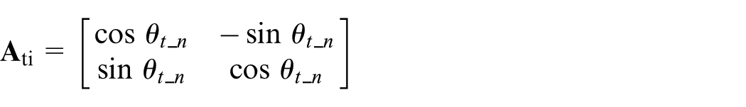

It obtains

Similarly


The minimum distance d1_n in distance trajectory curve of beam p1, which denotes the distance between the direction of wake breadth and wake centerline, is calculated by the golden section method. Rp1*_n in the curve has the minimum distance with beam p1. Its coordinate’s inertial frames are

According to the coordinates of Rp1*_n, the distance s1_n between Rp1*_n along the direction of wake and target position can be calculated.
The minimum distance d2_n and d3_n of detecting beam p2 and p3 can also be gained with the same method. Rp2*_n and Rp3*_n in the curve have respective minimum distance with beam p2 and p3. Their coordinates in the inertial frame are

and

The distance s2_n and s3_n between Rp2*_n and Rp3*_n along the direction of wake and target position is calculated.
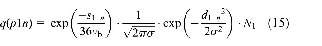
According to equation (4), the bubble density of the three beams at the n simulating moment is


The position of the next simulation time detecting beam in the inertial coordinate system is calculated by the assumed condition


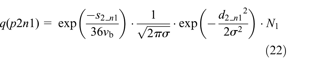
Then we can resolve beam p1, p2, p3, minimum distance d1_n1, d2_n1, d3_n1 with the target trajectory and minimum distance s1_ n1, s2_ n1, s3_ n1 between the three points and target position at the n + 1 moment. Through equation (3), we can gain


We calculate the wake density gradient along the direction of x-axis and y-axis in the supercavitating vehicle coordinate system (Figure 5).
Wake density gradient in the supercavitating vehicle coordinate system.
At the n moment, the bubble number density of A, B, and C three points are qp1n, qp2n, qp3n. Similarly, at the n + 1 moment, qp1n1, qp2n1, qp3n1 are obtained. Then, the gradients of point B in x-axis and y-axis are calculated in body axes coordinate system

Translate the wake gradient from the supercavitating vehicle coordinate to inertial frame, it is obtained as

where

We simulate the wake model by MATLAB. We can get bubble quantity density distribution model form.29,30 We set the target speed Vb = 20 m/s, initial extending angle α = 30°, vessel breadth B = 40.8 m, and terminal extending angle 1°, then we get the wake model of stationary target.
Figure 6 shows the wake gradient information of some regions. It can be seen that the gradient always points to the direction that the bubble number density becomes larger, that is, the centerline of the wake and the direction of the target. In Figure 7, z-axis denotes the size of bubble density, x-axis denotes the vessel speed direction, and y-axis denotes the direction of wake breadth. Figure 8 shows the schematic diagram of the wake model in x-y plane. Its horizontal direction denotes the direction of y-axis and lengthways direction denotes the direction of x-axis. As shown in Figure 8, the geometry of the wake model is consistent with that in the theory.

Part of the regional gradient vector.

Wake model of bubble density gradient.
Horizontal plane wake model geometry characteristics.
In Figure 9, z-axis denotes the size of bubble density; x-axis and y-axis constitute the plane inertial frame. Figure 10 shows the schematic diagram of wake model in x-y plane. As seen from Figures 9 and 10, the geometry characteristic of the established wake model in the horizontal plane meets with maneuvering target wake, establishing base for further guidance law deign. As shown in the figures, the wake model of the maneuvering target is given. As it is seen from the simulating graphic analysis, the attenuation of bubble density meets with data distribution law which is achieved from experiments. The nearer bubbles approach the vessel, the bubble density is larger. Along the direction of wake breadth, the maximum of bubble density is in the center. The wake model in horizontal plane corresponds with the wake’s geometry characteristic, certifying the validity of wake modeling.

Wake model of the maneuvering target.

Schematic diagram of wake model in x–y plane.
According to the relevant data, the Russian Navy’s wake-homing submarine tests nearly 20% of its guided faultage (reverse travel or lost targets). The faultage and hole in the wake are the main causes of the malfunction of wake-homing supercavitating vehicle. We model the faultage and analyze it. The length of the faultage is 30 m, the width is 20 m, and there are four faultages. The simulation condition is identical to that of the maneuvering target wake model, and the following results are obtained.
Figure 11 is the wake model of the maneuvering target after the faultages are added. Figure 12 is the geometric characteristics of the wake model after the faultages are added on the inertial horizontal plane, where the blank region is the faultages position. From Figure 11, one can hardly see the effects of faultages on the wake model. Figure 12 shows the faultages in the effective wake proportion.

Wake model of maneuvering target with faultages.

Plane geometry characteristics of wake model with faultages.
Research of the moving target wake in the three dimensions
At the direction of wake length, the bubble density is reduced with time and follows the exponential distribution. At the direction of wake width, it reaches his maximum in the center for the stirring of propeller and follows the GGD in the same deepness. The quantity of bubbles near sea surface decreases with the deepness and follows the exponential law, but in the deep layer, it decreases with the deepness and follows the power function law.
If z < 3 m

If z ≥ 3 m

where N denotes the size of bubble density in the arbitrary point and z is the sailing deepness of the vessel.
In order to make the wake model meet with the fact, σ is defined as a parameter, which has linear relation with s. Suppose d = 3σ in the wake boundary, then the bubble attenuation achieves a certain degree which is hardly to be distinguished with the bubble density in sea and is seen as wake boundary.
If

If

σ is defined as follows

As shown in Figure 13, the plane characteristics of the target wake model are given.

Plane characteristics of the target wake model.
Figures 14 and 15 are the tangent plane simulations of the vessel wake. Figure 14 is the bubble distribution of the wake centerline tangent plane. Figure 15 is the bubble distribution of the wake tangent plane that is 30 m away from the centerline.
Bubble distribution of the wake centerline tangent plane.
Bubble distribution of the wake tangent plane that is 30 m away from the centerline.
Figures 16 and 17 are the cross-section simulations of the vessel wake. Figure 16 is the bubble distribution of the wake cross section that is 50 m away from the vessel. Figure 17 is the bubble distribution of the wake cross section that is 100 m away from the vessel.

Bubble distribution of the wake cross section that is 50 m away from the vessel.

Bubble distribution of the wake cross section that is 100 m away from the vessel.
It can be seen from Figures 13–17, the bubble density at the direction of the wake length reduces with time and corresponds with the exponential distribution; it reaches its maximum in the center at the direction of wake breadth and satisfies the normal distribution in the same depth. What is more, the quantities of the bubbles around the water surface decrease with the depth and follow the exponential law, but in the deep layer, it decreases with the deepness and follows the power function law. In conclusion, the designed wake model reflects the basic characteristic rule of vessel wakes and laid the foundation for the guidance law design.
Guidance law of the wake-guided supercavitating vehicles
Guidance law design of maneuvering and non-maneuvering target
Based on the above gradient information model detected by laser, the laser homing guidance law is proposed.
Set
The guidance law is defined as
If

Else if
Else if

When approaching the vessel, the wake gradient changes a lot. In order to decrease the changes, in this study set k1 = 0.015.
To study the effect of the designed laser homing guidance law based on wake gradient information, the simulating experiment and result analysis are conducted. We suppose the target speed Vb = 15 m/s, the initial spread angle α = 30°, vessel width B = 40.8 m, initial target position (xb0, yb0) = (700, 10), the supercavitating vehicle speed is Vt = 100 m/s, set the initial supercavitating vehicle position at (xt0, yt0) = (800, 0), the launching time is t = 107 s, the supercavitating vehicle hitting deepness is 5 m, beam intersection angle θ = 45°, supercavitating vehicle’s maximum turning speed is 50 rad/s, and k in guidance law k = 0.075. The simulation results are shown in Figure 18. The maximum allowable miss distance is 1, and the minimum miss distance of the supercavitating vehicle is 0.8131.

Trajectory of the supercavitating vehicle and the moving target.
For non-maneuvering target, we suppose the target speed Vb = 20 m/s, the initial spread angle α = 30°, vessel width B = 40.8 m, initial target position (xb0, yb0) = (700,0), the supercavitating vehicle speed is Vt = 100 m/s, set the initial supercavitating vehicle position at (xt0, yt0) = (0, 100), the supercavitating vehicle hitting deepness is 5 m, beam intersection angle θ = 45°, supercavitating vehicle’s maximum turning speed is 50 rad/s, and k in guidance law k = 10. The simulation results are shown in Figure 19.
Trajectory of the supercavitating vehicle (red line) and the moving target (blue line) with non-maneuvering.
As shown in Figure 18, it is the supercavitating vehicle trajectory with laser homing guidance law based on wake gradient information. Compared with the target trajectory and the three traditional beam guidance trajectories, the supercavitating vehicle trajectory with laser homing guidance law based on wake gradient information has no access to target moving state. The supercavitating vehicle guided by the designed laser homing law can follow the maneuvering target accurately, sail in wake region from beginning to end. And from Figure 19, we can see that the supercavitating vehicle guided by the new guidance law follows the non-maneuvering target accurately too. This can not only decrease the requirement to the supercavitating vehicle’s maneuvering ability, but also enormously reduce energy consumption and increase supercavitating vehicle’s effective loading.
Design of homing wake guidance law with faultage
In order to test the effect of this guidance method when a fault occurs in the wake, a maneuvering target wake model with a hole is used as the target model to design the guidance law. The flowchart of the guidance program is shown in Figure 20.

The flowchart of the guidance program.
The size of the fault is different. If each simulation period is set to 0.1 s, it is judged whether the condition in the wake is three consecutive simulation cycles, and no signals are detected by the three detectors. The wake trajectory is still designed in accordance with the original guidance instructions. If the fault is entered, it can still ensure that the vehicle is in the wake, but there is no information about the wakes in the three detectors

When the three detectors fail to detect the wake signals in three continuous simulation cycles, the detection system gives the acquiescent fact that the supercavitating vehicle has been out of the wake region. The wake model of maneuvering target with fault is taken as the target, and the guidance law is simulated and verified. In order to compare the simulation results with Figure 18, the simulation conditions must be consistent with the simulation conditions of Figure 18. The trajectory of the supercavitating vehicle and the moving target with fault are as shown in Figure 21.

Trajectory of the supercavitating vehicle and the moving target with fault.
From the simulation results we can see that compared with the conventional navigation trajectory, faults in wake flow have almost no effect on the vehicle trajectory under this guidance, the target will not be lost because the faults disturbance, the purpose of precise attack can still be achieved. And in this case, the supercavitating vehicle is able to navigate in the wake of the ship to ensure severe maneuvering conditions.
Design of variable structure guidance law
Variable structure guidance law has a strong robustness for all kinds of uncertain factors. So the guidance law is used to compare with our wake-homing guidance law in this article.
The model of variable structure guidance law, mentioned before, of supercavitating vehicle is as follows
There are three parameters (

Trajectory of the supercavitating vehicle and the moving target using conventional variable structure guidance law.
Compare Figure 22 with Figure 18, we can see that the vehicle needs larger maneuvering, when hitting the target, using the conventional guidance law than using the new wake-homing guidance law in this article. Larger maneuvering makes against to stabilization of supercavitating. In addition, the conventional guidance law has a lower accuracy than the new guidance law.
Conclusion
This article has designed a new guidance law for wake-homing. The design method was simple and direct and avoided the cycling research which exists in traditional wake-homing. Whether the supercavitating vehicle enters into or goes through wake is no longer used as criterion of turning signal sent by the supercavitating vehicle control equipment. It observably decreases the requirement of the supercavitating vehicle’s maneuvering ability. The simulation results show that the supercavitating vehicle’s angle speed could reach maximum 100 rad/s. What is more, the guidance method is unrestrained in the supercavitating vehicle speed. It can make the supercavitating vehicle keep in wake from beginning to end and move along the centerline of wake, can decrease the rate of going through wake region and target loss. According to the deducing procedure of wake’s gradient information, the guidance law does not depend on the wake modeling, which meant that the guidance law is still applicative even bubble distribution characteristics in vessel wake are different. For supercavitating vehicle, a kind of high-speed underwater vehicle has good adaptability and has certain theoretical significance and engineering application value.
Footnotes
Handling Editor: Shun-Feng Su
Declaration of conflicting interests
The author(s) declared no potential conflicts of interest with respect to the research, authorship, and/or publication of this article.
Funding
The author(s) disclosed receipt of the following financial support for the research, authorship, and/or publication of this article: This study has been conducted with the support of the National Natural Science Foundation of China (grant no. 51206007), Aeronautical Science Foundation of China (grant no. 2013ZC51), and China Scholarship Council (CSC) (grant no. 20140625104).