
Abstract
In this study, in situ experiments were conducted to study the changing characteristics of the lateral and longitudinal resistance of a ballast bed, and a three-dimensional model for the ballast bed and sleeper was constructed based on the discrete-element method. The effects of the lateral and longitudinal resistance of the ballast bed, such as gravel ballast grading, sleeper depth, the angle of the shoulder slope, and ballast bed shoulder width, among others, were studied. The results suggest that (1) the lateral and longitudinal resistance of the ballast bed increases with the widening of ballast grading, and within the size distribution limits, the resistance of the ballast bed satisfies the specification; (2) the lateral and longitudinal resistance of ballast bed increases with an increase in the sleeper depth and the resistance of ballast bed satisfies the specifications for sleeper depth greater than 150 mm; (3) the lateral resistance of the ballast bed increases with a decrease in the angle of the shoulder slope, whereas the longitudinal resistance remains unchanged and the resistance of the ballast bed satisfies the specifications for slope gradient of 1:1.75 or less; and finally, (4) the lateral resistance of the ballast bed increases with the widening of the ballast bed shoulder, whereas the longitudinal resistance remains unchanged, and the resistance of ballast bed satisfies the specifications when the shoulder width is greater than 400 mm.
Keywords
Introduction
Ballasted tracks are traditional railway structures and are advantageous in terms of their low cost, low vibration and noise, and easy maintenance, among others. 1 Since a ballasted track is granular, it has complex mechanical properties. It resists the lateral displacement of the track frame, preventing the welded rail track from buckling and ensuring its stability. Furthermore, the ballast bed prevents the longitudinal displacement of the ballast track frame. 2 The quality of the ballast track bed is critical to the stability and the workload capacity of the track structure; the ballast bed receives the train load directly from the sleeper, maintains the sleeper pressure and track geometry, and provides rail elasticity and drainage. 3
The lateral and longitudinal resistance of the ballast bed has been extensively studied. Kwon and Tutumluer 4 used the BLOCK3D software to perform three-dimensional (3D) discrete-element modeling of the geometrical and mechanical behavior of the ballast particles. Lu and McDowell 5 used the PFC3D software to simulate the particle shapes and analyzed the fragmentation rules. They concluded that the characteristics of real angular ballast particles can be simulated when the number of ballast particles in the simulations is greater than eight. Khatibi et al. 6 explored the effect of shoulder height and sleeper type on the lateral resistance of the ballast bed. Le Pen and Powrie 7 studied the effect of the different sleeper bed, sleeper sides, and shoulder resistance in the laboratory. Koc et al. 8 studied the lateral ballast resistance as a function of the mechanical maintenance work and the sleeper load. Irazabl et al. 9 studied the influence of the sleeper load on the lateral resistance of the ballast bed. Kabo 10 used the finite-element method to build a model for the ballast sleeper bed model and investigated the effect of shoulder height and wheel load on lateral resistance. Yang and Zhu 11 conducted ballast bed resistance tests on ballast beds, road and bridge transitional sections, and bridge sections and obtained the equivalent lateral resistance of type III concrete sleeper with ballast. Ma et al. 12 studied the difference in the lateral resistance of ballast beds under different lower foundation conditions for different construction stages. Zhang et al. 13 studied the density and lateral and longitudinal resistance of ballast beds in the Qinghai–Tibet welded rail-track test section and obtained an equation for the lateral and longitudinal resistance of the ballast bed. Yang 14 analyzed the in situ and laboratory data statistically and assessed the lateral and longitudinal resistance of type III concrete sleepers.
However, the proposed research on the lateral and longitudinal resistance of ballast beds is mostly based on field tests, and there is relatively little research on discrete-element analysis. Field tests require a lot of manpower and material resources, interfere with normal operations, and are affected by external conditions. Discrete-element simulations can overcome these problems.
In this article, in situ experiments were carried out, and a 3D model for the ballast bed and sleeper was constructed based on the discrete-element method. The lateral and longitudinal resistance of the ballast bed was studied as a function of ballast grading, sleeper depth, the angle of the shoulder slope, and ballast bed shoulder width. A numerical simulation of the ballast bed was achieved, and the mechanical properties of ballast bed were revealed. These studies provide a reference for further study of the mechanical properties of the ballast bed, and the research results can also provide reference for design, construction, and maintenance of continuous welded rail.
Model establishment
The discrete-element method was first proposed by Cundall. 15 By using a disk or sphere as the basic unit, we can simulate the interaction and movement between particles based on the mean of noncontinuous numerical solutions. PFC3D is a numerical analysis software based on the discrete-element method that is used to study the mechanical properties of particles from a microscopic point of view, and the mechanical behavior of the model system can be modeled by a series of randomly shaped particles. 16 It is also possible to analyze the interaction and kinematics of complex particles. In this study, a 3D ballast bed discrete-element model was built. 17 In this model, the width of the ballast bed is 3.6 m, the thickness is 0.35 m, the angle of the shoulder slope is 1:1.75, and it was assumed that ballast particles of various sizes were randomly distributed over the ballast bed. Because of the limitation of calculation efficiency and the sleeper displacement is very small compared with the size of the ballast bed, this model uses ballast bed with one sleeper to simulate, as shown in Figure 1.
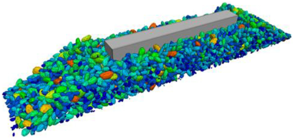
Sleeper-ballast bed three-dimensional model.
A spherical particle bed model is generated based on the high-speed railway grading specifications, principles of same volume, same position, equal mass, and spatial randomness for the clumped particles in the long axis. The more ball particles make up a clump, the more accurate the shape characteristics of the ballast is and the greater is the complexity of the computations. 18 For improved computational efficiency and simulation precision, the number of particles in a clump better reflecting the degree of engagement among particles is greater than eight. 19 In this study, five kinds of typical ballast particles are considered, to ensure the correctness of the simulation, the number of spheres used in the five typical ballasts should be minimized, use 8, 9, 9, 11, 13 spheres, respectively, and the average number of spherical particles in a clump is 10.
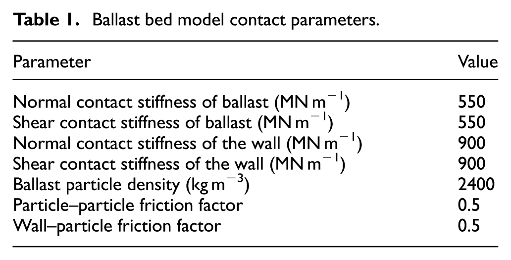
A clump is a collection of rigid spherical pebbles. The clump surface is defined by the pebble positions and the clump radius, and the surface properties of a clump can be specified independently for each particle. 20 Clumps can simulate any ballast shape. Interior ballast particles are not connected by broken bonds and there is no force between neighboring particles. To simulate the flat and continuous sleeper surface, a wall is used, and the number and size of the contact forces between the wall and ballast particles is considered; however, there is no weight in the model wall of PFC3D, and the wall stability is high when clumps are used to simulate the ballast. 21 The flowchart of building discrete-element model is shown in Figure 2. The selection of parameters is based on a large number of numerical calculations and related experimental analysis and has been referenced by studies of Lu and McDowell,5,19 Lim and McDowell, and so on. 22 The model parameters are given in Table 1.

The flowchart of building discrete-element model.
Ballast bed model contact parameters.
Model verification and analysis
To verify the accuracy and mechanical properties of the discrete-element model of the ballast bed resistance, the ballast bed of the intercity railway of Changsha–Zhuzhou–Xiangtan (Changsha, Zhuzhou, and Xiangtan are three cities in Hunan province of China. This intercity railway is an important line to connect the three cities, and the experimental data were tested on this railway) was used. In situ tests along the line were carried out. The lateral resistance of the ballast bed was tested by releasing all fasteners from the measured sleeper and removing the rail plate. A hydraulic jack, force sensor, and a counter-force frame were installed at the sides of the sleeper, while the steel rails and mass of the measuring device provided the lateral force to the sleeper. A hydraulic jack provided the lateral force that was measured with a force sensor, and dial indicators were installed on one end of the sleeper and on the steel rail to measure the lateral displacement (Figures 3 and 4).

Lateral resistance measurements (schematic).
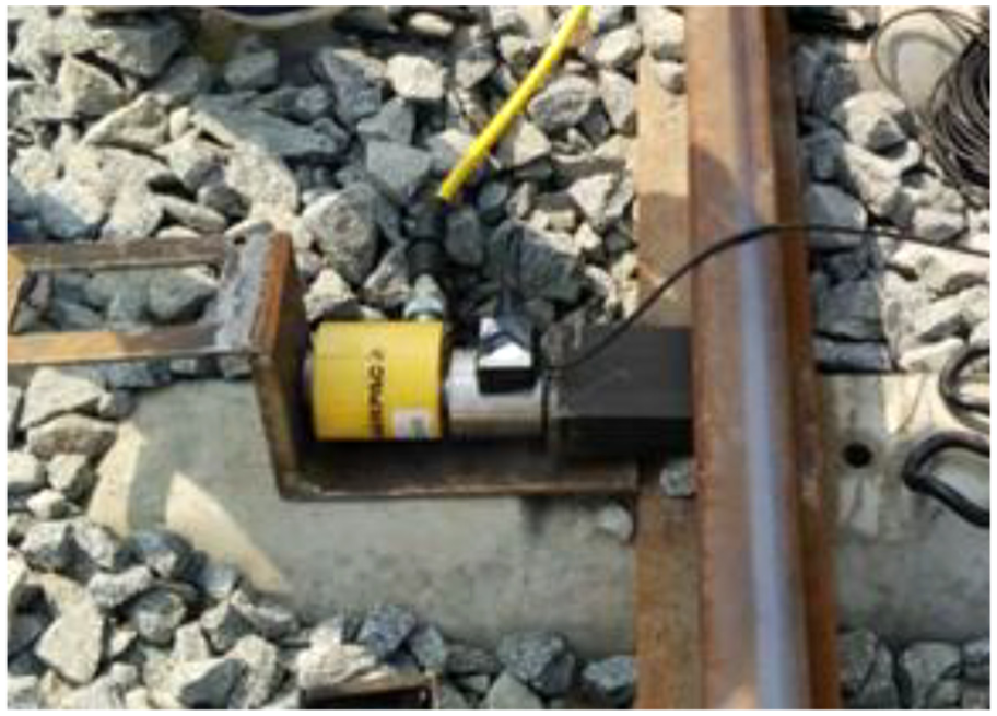
Lateral test loading (field example).
To test the longitudinal resistance of the ballast bed, the hydraulic jack, force sensor, and device bracket were installed on the middle of a measured sleeper and an adjacent sleeper. The dial indicators were installed on both sides of the sleeper, and the magnetic base of the dial indicators adsorbed the vibrations from the both the sides of steel rail. Thus, we obtain the curve between longitudinal resistance and sleeper displacement. The setup for monitoring the longitudinal resistance of the ballast bed and the sleeper are shown in Figure 5. The field test setup is shown in Figure 6.

Schematic of the test setup.
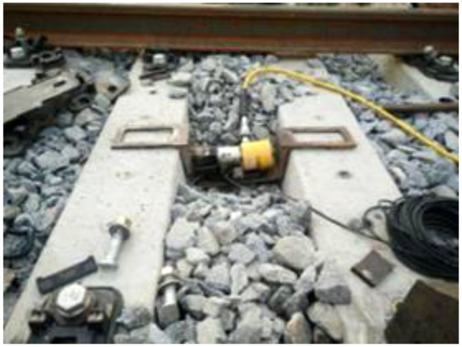
Field setup of lateral test loading.
In this 3D model of discrete element, a sleeper speed of 0.5 mm/s is applied in the lateral and longitudinal directions. The relationship between the force of the sleeper and the sleeper displacement was recorded through the history function of PFC3D. The lateral and longitudinal resistance of the ballast bed and the lateral and longitudinal displacement of the sleeper, both in situ and model data, are shown in Figures 7 and 8.

Ballast bed lateral resistance versus lateral displacement of the sleeper.

Ballast bed longitudinal resistance versus longitudinal displacement of the sleeper.
The fitting curve to the data in Figures 7 and 8 are based on a power function. For sleeper displacement of 2 mm, the in situ lateral ballast resistance is 15.13 kN, whereas the simulation value is 15.97 kN. For in situ longitudinal ballast resistance of 22.45 kN, the simulation value is 23.34 kN. The correlation coefficients between in situ test and simulation values are 0.958 and 0.928. Thus, it is inferred that the ballast bed model correctly describes the relation between bed resistance and sleeper displacement. Literature data suggest that the relation between the lateral resistance value (Q) of the ballast bed and the lateral displacement y of the sleeper is given by the following equation 23

where
Factors controlling the ballast bed resistance
The lateral and longitudinal resistance of the ballast bed is critical to the ballast bed quality.24,25 There are many factors that affect ballast bed resistance, such as ballast grading, sleeper depth, the angle of the shoulder slope, and ballast bed shoulder width. Figure 9 shows the contact force network in the ballast bed particles when the sleeper is pushed laterally. Figure 10 shows the contact force network in the roadway particles when the sleeper is pushed longitudinally. The degree of contact is used to represent the intensity of the contact force among particles.
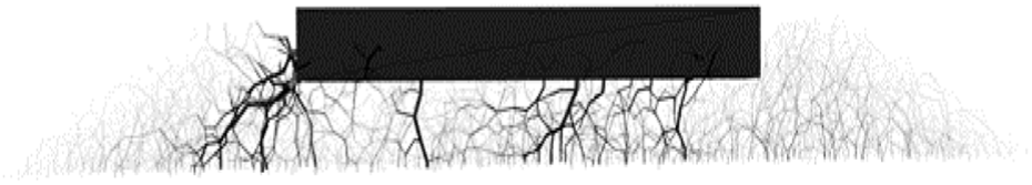
Lateral resistance contact force network.
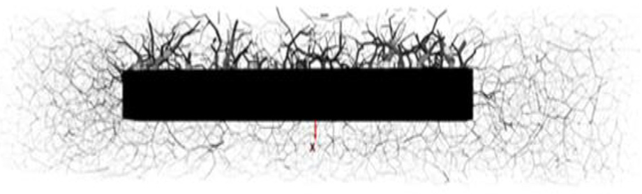
Longitudinal resistance contact force network.
Ballast grading
The ballast particles are classified as gravel and the particle-size distribution affects the mechanical properties, strength, and stability of the ballast bed, as well as the maintenance and repair of the ballast bed. Furthermore, the ballast grading affects the residual deformation of the ballast bed and particle crushing capacity. 26 Currently, there are specific grading requirements (Figure 11) for high-speed railway ballast. We use the PFC3D software to build a full-size ballast bed model and study the effect of particle-size distribution on the lateral and longitudinal resistance of the ballast bed.

Ballast grading specifications for high-speed rail.
In this study, the ballast grading is divided into three cases. Condition 1 is the upper limit, condition 3 is the lower limit, and condition 2 is the upper and lower limit interpolation. The relation between the ballast bed lateral resistance and ballast grading is shown in Figure 12 and that between the ballast bed longitudinal resistance and ballast grading in Figure 13.
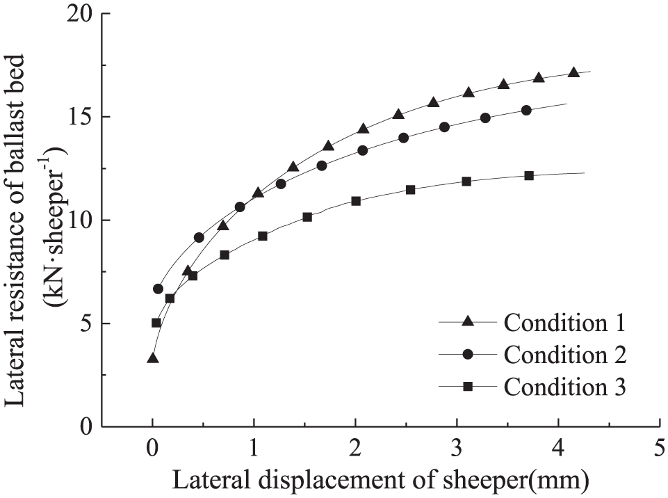
Relation between ballast bed lateral resistance and ballast grading.
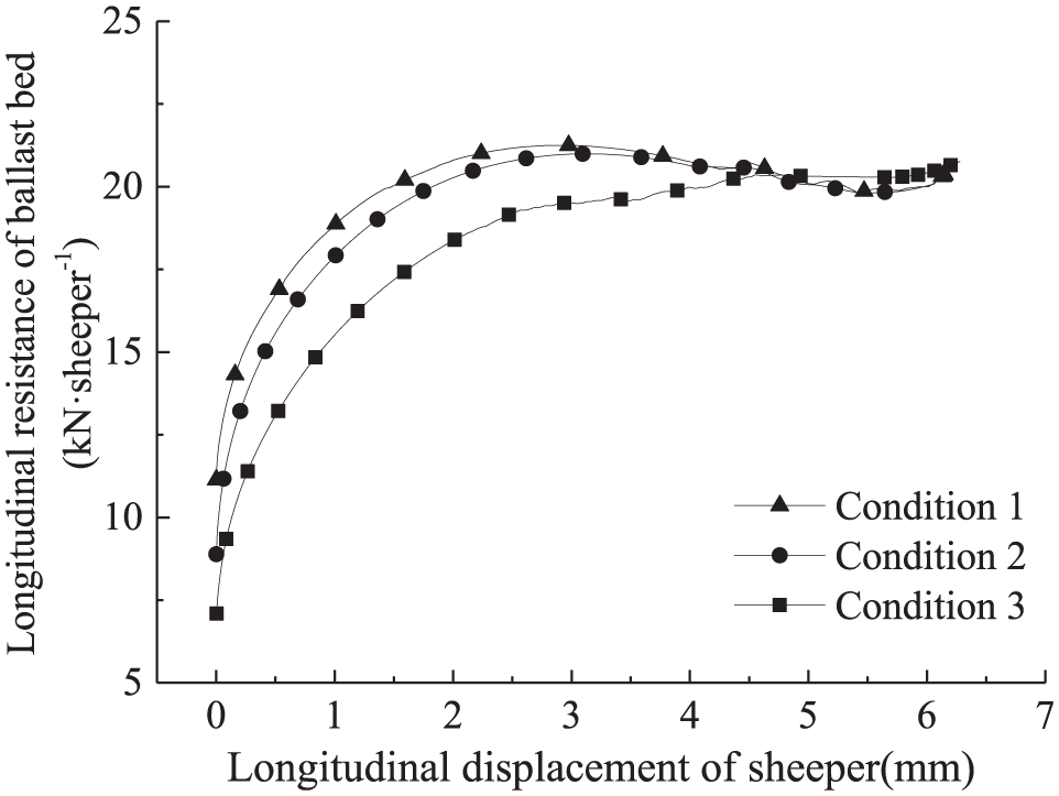
Relation between ballast bed longitudinal resistance and ballast grading.
From the lower to upper limit, the fine particles increase, the total number of ballast particles per unit volume increases, and the ballast grading envelope widens, as shown in Figures 12 and 13. In addition, the lateral resistance of the ballast bed is 10.92, 13.25, and 14.22 kN, and the ballast bed longitudinal resistance is 18.36, 20.27, and 20.8 kN. Both the lateral and longitudinal resistance gradually increase as the ballast grading envelope widens and more fine particles fill in the gaps between the coarse particles. Ballast bed density increases, the ballast bed force is better transmitted, the ballast bed settlement decreases, and the service life of the ballast bed increases. 27
Sleeper depth
In a ballast bed, a sleeper is surrounded by gravel that limits its displacement and increases the ballast bed resistance, and sleeper depth has a great influence on the ballast bed resistance. 28 In this study, 3D discrete-element models with 100, 150, and 200 mm sleepers were considered. The relation between the lateral resistance of the ballast bed and the depth of the sleeper is shown in Figure 14 and that between the longitudinal resistance of the ballast bed and the depth of the sleeper is shown in Figure 15.

Ballast bed lateral resistance vs later displacement of the sleeper.

Ballast bed longitudinal resistance and longitudinal displacement of the sleeper.
As it can be seen from Figures 14 and 15, with an increase in the sleeper depth, the resistance of the ballast bed gradually increases; the lateral resistance of ballast bed is 7.89, 15.47, and 17.39 kN and the longitudinal resistance of ballast bed is 15.34, 22.83, and 29.10 kN. The rate of the lateral resistance decreases with an increase in the sleeper depth, whereas the rate of the increase of the longitudinal resistance of the ballast remains constant. The capacity of the ballast to fix the sleeper and prevent its displacement increase with the depth of the sleeper increases. However, the resistance of the sleeper bottom remains constant owing to the positive pressure and the constant damping of the sleeper bottom. The sleeper lateral movement pushes the ballast, and the lateral resistance of the ballast bed increases because of the sleeper shoulder. Thus, an increase in the ballast shoulder height can effectively increase the lateral resistance. At the same time, the resistance of the sleeper side also increases. According to the TB 10754-2010 high-speed railway track construction quality acceptance criteria states that “The lateral resistance of the ballast bed is greater than the 12 kN per sleeper, and the longitudinal resistance of the ballast bed is greater than the 14 kN per sleeper,” we see that the 150 and 200 mm sleeper depth satisfies the specification requirements, while the initial lateral and longitudinal resistance of the ballast bed increases with an increase in the sleeper depth. The initial lateral resistance of the ballast bed is 3.361, 6.723, and 8.352 kN, and the initial longitudinal resistance of the ballast bed is 5.281, 12.231, and 16.935 kN. Clearly, the lateral and longitudinal resistance of the ballast bed increases with an increase in the sleeper depth. For type III sleepers, the under-the-rail sleeper height is 230 mm and the central sleeper height is 185 mm, and when the depth exceeds the height of the central sleeper, ballast particles may be scattered in the sleeper upper surface. This affects the train running; therefore, the recommended depth for type III sleeper is 185 mm.
Shoulder slope
The angle of the shoulder slope is critical to the ballast bed stability. 29 The latter mainly depends on the friction angle of the ballast, friction, and shoulder width. The greater the internal friction angle of the ballast is, the higher the friction is, which increases the stability of the shoulder slope and thus the shoulder width can have a high gradient. 30 The angle of the shoulder slope is important to the ballast bed type and construction costs. In various countries, the angle of the shoulder slope is 1:1 or 1:2.5. For China, the slope of each type of ballast track is listed in Table 2.
Shoulder slope gradient.

The slope gradient is set at 1:1.50, 1:1.75, and 1:2 to explore the effect of slope gradient on the lateral and longitudinal resistance of the ballast. Figures 16 and 17 show the relation between the resistance of the ballast bed and slope gradient.

Lateral resistance of ballast bed versus lateral displacement of the sleeper at various slope gradients.

Longitudinal resistance of the ballast bed versus lateral displacement of the sleeper at various slope gradients.
As it can be seen from Figures 16 and 17, the lateral resistance of the ballast bed is 10.06, 15.97, and 17.86 kN, and the longitudinal resistance of the ballast bed is 22.84, 21.96, and 22.43 kN. With the slope gradient change decreases, the lateral resistance of the ballast beds increases slowly, but the longitudinal resistance remains unchanged, and the number of ballast particles on both sides of the sleeper shoulder increases. Consequently, the shoulder resistance increases. The results suggest that for shoulder slope gradient of 1:1.75 or lower, the lateral resistance is 12 kN per sleeper and the longitudinal resistance is 14 kN per sleeper. Furthermore, the smaller the slope gradient is, the wider the bed bottom becomes, which increases the construction cost. Bridge and tunnel sections are also subject to space constraints; thus, a slope gradient of 1:1.75 is recommended.
Shoulder bed width
The length of the ballast bed beyond the sleeper is the ballast bed shoulder width and prevents the ballast from being pushed out of the sleeper because of the vibrations. 31 Thus, the density of the ballast bed is maintained. In general, the ballast track bed shoulder width in noncontinuous welded rail tracks is 200–300 mm and in continuous welded rail tracks is 400–450 mm. In the discrete-element model, we use ballast bed shoulder widths of 200, 400, and 600 mm to study the effect of shoulder width on the lateral and longitudinal resistance of the ballast bed. Table 3 shows the shoulder slope and shoulder bed width. Figures 18 and 19 show the lateral and longitudinal resistance of the ballast bed versus the lateral displacement of the sleeper for different shoulder widths.
The shoulder slope and shoulder bed width.

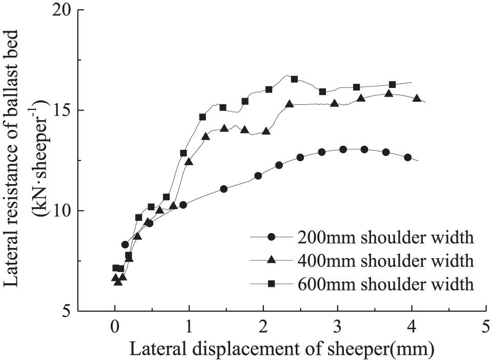
Lateral resistance of the ballast bed versus lateral displacement of the sleeper for different shoulder widths.

Longitudinal resistance of the ballast bed versus the lateral displacement of the sleeper for different shoulder widths.
As it can be seen from Figures 18 and 19, the lateral resistance of ballast bed increases (11.97, 13.89, and 15.97 kN) with an increase in shoulder width of the ballast bed, and the longitudinal resistance of ballast bed is nearly constant or slightly increases (18.84, 19.67, and 20.19 kN). This is mainly due to the higher shoulder width of the ballast bed and higher number of particles on both sides of the sleeper. The greater the ballast shoulder resistance is, the higher the lateral ballast resistance is, whereas the longitudinal resistance of the ballast bed does not change much. The results suggest that for ballast bed with shoulder width of 400 mm or larger, the lateral resistance satisfies the limit of 12 kN per sleeper and longitudinal resistance satisfies the limit of 14 kN per sleeper.
Conclusion
In this article, the lateral and longitudinal resistance of ballast bed was tested by conducting in situ experiments, and ballast bed-sleeper discrete-element model was established to verify the correctness of the model. This model can correctly reflect the mechanical characteristics of the bed resistance, and the influential factors of the lateral and longitudinal resistance such as ballast gradation, depth of sleeper, shoulder slope gradient, and shoulder width of ballast bed were studied through this model. The proposed study can be concluded as follows:
For a wide ballast grading envelope, the fine particles increase and fill the voids between coarse particles. This consequently increases the ballast bed density, and the lateral and longitudinal resistance of the ballast bed. For ballast grading within the particle-size distribution upper and lower limits, the resistance of the ballast bed satisfies the specifications.
The constraints hindering effect on the sleeper ballast increases with an increase in the sleeper depth, and the lateral and longitudinal resistance significantly increase. For sleeper depth greater than 150 mm, the resistance of the ballast bed satisfies the specifications.
As the shoulder slope gradient decreases, the lateral resistance of the ballast bed increases and the longitudinal resistance remains unchanged. For shoulder slope gradient of 1:1.75 or less, the ballast bed resistance satisfies specifications.
With an increase in the shoulder width of the ballast bed, the lateral resistance of the ballast bed increases and the longitudinal resistance remains unchanged. For shoulder width greater than 400 mm, the resistance of the ballast bed satisfies the specifications.
Footnotes
Handling Editor: M A Hariri-Ardebili
Declaration of conflicting interests
The author(s) declared no potential conflicts of interest with respect to the research, authorship, and/or publication of this article.
Funding
The author(s) disclosed receipt of the following financial support for the research, authorship, and/or publication of this article: The research is financially supported by the Graduate Innovation Project of Central South University (grant number: 2018zzts654), the Major Program of National Natural Science Foundation of China (grant number: 11790283), the High-speed Railway Joint Fund of National Natural Science Foundation of China (grant number: U1734208), and the Science and Technology Foundation of China Railway 14th Bureau Corporation Limited (grant number: 20160016), which are gratefully appreciated.