
Abstract
Snake robots have come to represent a new subfield of bionic robot research in recent years. A snake robot comprises many modules and performs various movements in arranged connections. The structure of a snake body enables it to move smoothly in narrow spaces or pipes with high stability and reliability. This article studies the application of a snake robot on a large-scale nuclear power facility to sense in pipe components. Therefore, a snake robot must move in pipes in which high radiation is present to explore the surrounding environment and take samples. A simple but effective method of locomotion is developed and executed to confirm feasibility of motion, especially in narrow space. A sampling mechanism with a storage box is designed at the tail of the snake to take and keep the samples well at designated locations. We built a pipe system which has two right-angled turns to simulate the pipes of a large-scale nuclear power facility. A user interface helps operators to manipulate the snake robot.
Keywords
Introduction
In recent years, some nuclear power plants in Taiwan are planned to decommission. However, the management, maintenance, and repair of internal pipelines of nuclear energy components of the nuclear power plant is very difficult, because the pipelines are disposed densely and have various structures, and it is also unable to enter the pipelines for check, because the check operation must build construction frames and deconstruct the adiabator first. For this reason, a snake robot having advantages of small size, multiple degrees of freedom, lightweight, simple operation, easy installation, and repair is expected to assist in decommissioning a nuclear power plant. Besides the nuclear power plant, a petrochemical industry plant must be continuously operated for a long time and cannot be shut down for periodic maintenance and repair anytime, so the petrochemical industry plant also has risks of pipeline corrosion, pipeline breakage, pollution due to pipeline leakage, or fire explosion. If the snake robot can be applied to detect hazards and redraw the pipeline map, the hazard risk of the nuclear power plant or the petrochemical industry plant can be greatly reduced.
Snake robots are capable of contributing to the environments that may either be too narrow or too dangerous.1–5 Owing to the excellent mobility on various terrains, snake robots play a crucial role in biomimetic robotics. The concept of snake robots was first proposed by a Russian constructivist artist, Petr Miturich, in the 1920s. He developed various designs that could operate on land, in air, or water without an external power source or control. In recent decades, a wide range of snake robots have been developed. Various mathematical models and motion patterns were also presented for snake robots.6–8 Yu et al. 9 developed the control and modality of a snake robot to move in a three dimensional (3D) pattern. The central pattern generator (CPG) models for snake-like robots are presented in Rezaei et al., 10 Zhang et al., 11 Bing et al., 12 and Qiao et al. 13 Although their research varies greatly in physical configuration and purpose, they all mimic the locomotion of snakes. However, most of the controllers, based on a mathematical model of the structure of the robots (snake), are complex and depend on an understanding of the dynamic equations of locomotion.
Besides, there are several researches related to the snake robot design over the years. Dowling 14 designed robots for the limited size or shape of environment where appendages such as wheels or legs cause entrapment or failure. Arvin et al.15,16 presented using infrared (IR)-based communication technique for swarm robots to share data. Tuncer et al. 17 tried to find a feasible path for mobile robots to move from a starting node to a target node in an environment with obstacles. A genetic algorithm is used to generate an optimal path by means of the information from camera and image processing. Pasarica et al. 18 presented using eye tracking technology to control a robotic platform. Several papers also discuss path planning problems of robots for efficient control.19,20 With these techniques, the robotic locomotion can be efficiently localized.
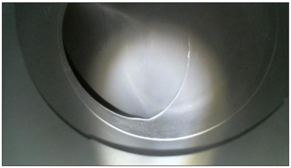
This article discusses radiation/pollution inspection in the pipes of a large-scale nuclear power mechanism using a snake robot. Before the decommissioning operation of the nuclear power plant, a multifunctional snake robot is applied to draw the pipeline map, detect dose, and sample nuclide. When detecting pollution or doing maintenance in pipes, a snake robot is suitable to control slowly and remotely for safety reasons. Figure 1 represents the pipes of a demineralized water system for fuel cell of a Taiwan nuclear power research reactor. The piping system is made of polypropylene (PP) of diameter 9–20 cm. Several pipes were connected with right-angled fittings in the mechanism. Therefore, the motion in pipes (especially in narrow space and at a right-angled turn) for a snake robot is studied in this article. Besides, it is important for a snake robot to take samples in pipes for a variety of analyses. Therefore, a sampling mechanism along with the proposed snake robot is also developed and its feasibility tested. Moreover, in order to safely keep the samples, we also design two storing boxes accompanied with the sampling module at the tail of the snake robot.

The piping system of a nuclear power mechanism.
The proposed work develops a snake robot using smart motors. Every two motors constitute a module of the snake body, in charge of two degrees of freedom (DOFs), yaw, and pitch, as shown in Figure 2. In general, the longer snake body (constructed using more motors) can produce more torque contributing to snake mobility. However, it is not easy for a long snake robot body to move in a narrow environment with right-angled turn. So, totally five modules (10 smart motors) are connected in serial to compose the snake body. A charge-coupled device (CCD) camera and a light-emitting diode (LED) are installed in front of the first module as the snake head for visual motoring of snake operator via a user interface (UI). A sampling mechanism is set at the snake tail. A simple but effective control algorithm is used to manipulate the snake robot. Typically, the bodies of snakes are elongated and include a long backbone that is made of 100–400 vertebrae. The four major snake gaits are serpentine, concertina, side winding, and caterpillar (rectilinear). 9 In the serpentine motion, all parts of the snake body move at the same speed and are in sliding contact with the ground. This gait is the most suitable for moving in a small area like a pipe in a nuclear power facility. In addition, the other three gaits are related to the serpentine type motion. Accordingly, this work develops a serpentine-like motion for a snake robot to move in a pipe.

The snake robot. (a) Snake body. (b) Silicon pads.
The rest of this article is organized as follows. Section “Structure of the snake robots and sampling mechanism” reveals the detail structure of the proposed snake robots and the designed sampling mechanism. In section “Snake motion algorithm and UI,” the control algorithm and UI for the snake operator were addressed. The experimental results, including the experimental environment, the locomotion of snake, and information for the UI are given in section “Experimental results.”
Structure of the snake robots and sampling mechanism
In the proposed design, the motors of the snake robot are connected through active joints that allow motion in the horizontal plane. To optimize the posture control, the snake structure is designed such that for each joint, a smart serial servo motor (DYNAMIXEL AX-12A) directly controls the angle between one link and the next. Each motor includes its housing, is with 32 × 50.1 × 40 mm3 and weight 54.6 g, and can perform rotation for yaw or pitch to 300°. Totally, one head (CCD and LED) and one tail (sampling mechanism) modules were assembled to form the snake-like robot for sensing pipes that were used in the experiments herein, as presented in Figure 2(a). A sampling mechanism sets at the snake tail for sensing pipes and taking samples. The silicon pad was used to cover the snake robot to increase the friction between snake body and the ground, as shown in Figure 2(b). With yaw modules and pitch modules interlaced, the snake-like robot can exhibit serpentine and other motions. 11
The CCD and the LED at the head module help the snake robot operator to see the detail inside the pipes with the UI. Besides, there is a sampling mechanism which is attached on two stepping motors, set at the tail of the snake robot. Since we can analyze the dust by wiping the pipe wall to realize radiation or pollution material in a nuclear power mechanism, therefore, two samplers are designed along with the snake robot to take samples in the pipe, such as shown in Figure 3. Each sampler is carried by a servo motor (MG90S) and has a soft brush on the top, staying in the storage box during the snake robot motion. An Arduino-based controller is applied to control both the stepping motors. When the snake robot arrives at specific locations, the operator can command the snake robot to take samples. So, the left or right stepping motor (MG90S) will rotate clockwise up to 120°, the brush can hence wipe the pipe wall to take the dust sample. After that, the stepping motor will rotate again to pull the brush back and keep the sample in the storing box with a protection gate. Hence, the samples can be safely kept and will not get pollution during the snake robot motion. The brush here can be also replaced by cotton swabs or a piece of cloth, based on the practical situation.

The schematic of the sampling mechanism.
The apparatus of the sampling mechanism is shown in Figure 4, where Figure 4(a) is the picture of the practical sampling mechanism at the snake tail and Figure 4(b) illustrates the tail module with two storing boxes, which were made by 3D printer. Figure 4(c) illustrates the process of taking sampling.

The apparatus of the sampling mechanism (a) without storing box, (b) with storing box, and (c) sampling process.
Snake motion algorithm and UI
Rather than developing a method for the snake robot using a complex mathematical model, this work uses a simple but effective algorithm to realize the serpentine-like locomotion in pipes for the proposed snake robot. The algorithm exploits the friction between the body and the ground to generate the propulsive force, making the motion of the snake robot similar to a sinusoidal movement serpentine locomotion. An approximate computation of the required structure of the snake robot must be carried out.
We use the first motor to carry the CCD and control the direction of CCD for taking images and video in the pipes. The control of the rest nine motors is shown in the following. Figure 5 presents the nine motors of the snake structure and their segments in the initial state. The body length of the snake robot, excluding the head and tail modules, is

Serpentine-like curve.
The joint function of the motors for performing serpentine-like locomotion is established as follows:

where

Therefore, initially amplitude for each motor will be

Then, the angles of rotation of the motors are computed. The tangent at each joint is

for
Therefore, the snake robot will perform serpentine-like curve at the start.
Figure 6 depicts the control flowchart of the proposed snake robot. The green block shows the UI and the remaining parts are the components of the snake robot. A UI is made using the LabView software for the operator to control and realize the present situation of the snake robot. The control command is also conducted using LabView and transferred to the smart motor of the snake robot using a universal serial bus (USB) port. A USB to a transistor–transistor logic (TTL) interface is applied to transmit the activation signal to the sample motor and convert the serpentine-like movement instruction to the smart motor (blue signal flow). All motors can be driven simultaneously, so that the body of the snake can curl up into a sine wave. All segments are then identically rotated from period to period. Thus, the snake robot exhibits the serpentine-like curve. Figure 7 presents the design circuit, the head module, the snake body and the sampling devices are all included. In the meantime, the CCD camera takes the video and shows on the UI for visual monitoring, such as shown in Figure 8. Accordingly, the snake robot operator can make a decision to go straight forward or turn left and right using the proposed serpentine-like method.

Block diagram of the snake robot and the UI.

The circuit designs of the proposed snake robot and sampling devices.
The CCD monitoring result.
Experimental results
A pipe system was built from 6 in-long acrylic pipes, as shown in Figure 9. The site requires not only straight forward motion locomotion, but also two right-angled turns, as would be found in a large-scale nuclear facility. The size of the experimental testbed is also shown. Since the diameter of the pipes is 6 in, approximately 15 cm and the system includes two right-angled turns,

The experimental pipes.
When the snake robot is outside the pipe system, the CCD at the head module helps to locate the entrance of the pipe system and the smart motor controller then drives the snake robot to enter the pipes. After the snake robot enters the pipe, it exhibits the serpentine-like motion, consistent with the proposed method, to move straight forward, to turn left, or to turn right. When the image sensor in the head module detects that the snake robot must turn left (right),
Besides, the snake robot is connected by several serial motors. Its locomotion in a narrow space may be turned over because the wall of the PVC pipe is not flat. Since silicon pads are applied to cover the snake robot body (Figure 2(b)), therefore, even when the snake robot has turned over from its original situation, the snake robot can still move smoothly in pipes.
Figure 10 presents the straight forward motion of the snake robot. Figures 11 and 12 show its turning left and right, respectively. The results for the snake robot to go backward and turning right locomotion present the similar results. Pictures of the snake robot are captured at different times to reveal its operations.
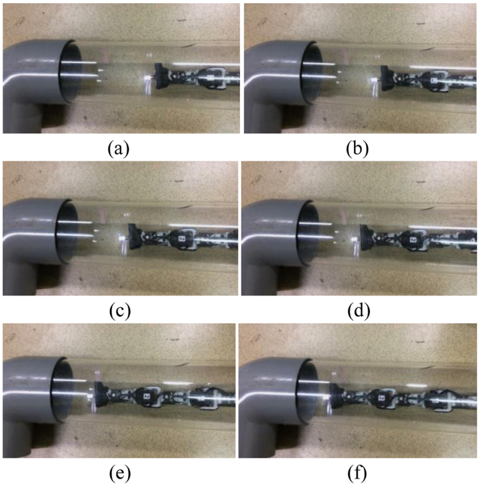
Straight forward locomotion in the pipe: (a) 0 s, (b) 3 s, (c) 6 s, (d) 9 s, (e) 12 s, and (f) 15 s.

Turn left locomotion in the pipe: (a) 0 s, (b) 2 s, (c) 4 s, (d) 6 s, (e) 8 s, and (f) 10 s.

Turn right locomotion in the pipe: (a) 0 s, (b) 2 s, (c) 4 s, (d) 6 s, (e) 8 s, and (f) 10 s.
Figure 13 shows the performance of the sampling mechanism. There are two sampling brushes at left and right sides of the snake tail. Therefore, the snake robot can perform sampling task twice and store the samples in the storage box.

Sampling in the pipe: (a) left, (b) right.
Figure 14 shows the map of the snake robot locomotion of the UI, where the blue, red, and green dots present the trajectory, current, and sampling locations. First, we have to define the trail of the piping system. Then, the picture is made by recording the instruction cycles to the motors. The accuracy is good enough for the snake robot to move in the piping system of a nuclear power mechanism. So, it will be easy for the operator of this snake robot to realize the practical situation in the piping system.

Map of snake robot locomotion.
The proposed snake robot is controlled by a low-cost microprocessor and the LabView-based UI. Besides, the sampling mechanism is made by stepping motors and the storing boxes are made by 3D printer. We made this snake robot according to the need of sensing pipes in a large-scale nuclear power facility. Compared with other industrial products (usually costing more than US$10,000), the cost of the proposed snake robot is relatively low and the robot functions can be changed according to the operator’s need. The length of the snake robot can also be tuned. The price of the main components of the proposed snake robot is shown in Table 1.
The price of the snake robot.

Remarks
The presented snake robot includes functions of moving in pipelines, sampling, image capturing, and map creation. The proposed controller is designed to drive the motors moving like a snake. Compared with existing snake robots, the proposed method presents a simple but effective solution for pipelines inspection. Also, the proposed control algorithm is efficient to move the rigid snake body on the smooth surface in a circular pipe system with rectangle turns. Figure 15 illustrates a schematic block diagram of the proposed work; a monitoring PC is used to display the movement trace of robot and the map creation of the pipelines.
A UI (Figure 16) is designed by LabView. The real-time image in the pipe is displayed using the camera at the head module. The trace map shows the movement trace of the snake and displays a color dot to indicate the sampling location for inspection. Several functions and commands are included in the UI for the snake robot operator to control the robot and collect samples.

The schematic block diagram of the proposed work.

The user interface.
Conclusion
This work described the design and features of a low-cost snake robot that exhibits the serpentine movements of real snakes. The proposed work uses a simple algorithm based on angular changes of various segments of the robot to move the snake robot in narrow space such as in a pipe. The proposed method, which exploits friction between the snake robot and the pipe, moves the snake robot forward and enables it to make right-angled turns easily. Also, the proposed serpentine-like curve method controls the speed of the snake robot easily. Compared with other industrial products, the presented snake robot not only gives the same sensing function, but provides the additional ability to sample and record the sampling location.
Footnotes
Handling Editor: James Barufaldi
Declaration of conflicting interests
The author(s) declared no potential conflicts of interest with respect to the research, authorship, and/or publication of this article.
Funding
The author(s) disclosed receipt of the following financial support for the research, authorship, and/or publication of this article: This work was supported in part by the Institute of Nuclear Energy Research, Taiwan under Contract No. 1042001INER036.