
Abstract
Remanufacturing technology has a wide range of applications in the repair of scrapped parts with a certain remaining service life. In this work, a scrapped crankshaft fabricated from nodular cast iron that had failed from working surface wear was remanufactured via a plasma cladding process. Taking into account the wear amount on the working surface and the characteristics of nodular cast iron, in this article, cladding layer parameters were designed and two types cladding powders, Fe-based and Ni-based, were prepared, respectively, to perform the cladding experiment. After examining different process parameters, relatively smooth cladding layers were obtained using four powders. The cladding experiment results showed that the powder No. 3 exhibited superior qualities when combined with proper processing parameters. When applying powder No. 3 to the main journal of crankshaft, a higher quality of cladding layer was achieved.
Introduction
Nodular cast iron has been widely used as substitute for steel in crankshaft, connecting rod, gear and similar parts requiring high strength, good toughness, low cost, and high yield ratio. These parts are often scrapped owing to the wear and tear of work surfaces after a long working time. Traditional surface treatment technologies, such as nitriding, carburizing, thermal spraying,1,2 and remelting3–5 are usually used to improve the wear resistance of these parts’ working surface and have vast applications. However, these technologies have some limitations for the scrapped parts with a certain remaining service life.
With the development of high-density energy heat-treatment technologies, cladding surface modification technology has developed rapidly. Because a higher strength metallurgical bond forms between the cladding layer and the substrate, and cladding layers have excellent comprehensive properties, cladding technology has become a topic of great research interest. Since began to be used to repair turbine engine blades, 6 it has been extensively used in the surface modification and remanufacturing of aircraft, automobiles, mining machinery, petroleum/chemical industry equipment, and so on.7–10 The heat source used in cladding technology primarily consists of laser and plasma beams.11–13 Research into laser cladding is comparatively mature, but the technique has higher costs and requires special working conditions. Although higher heat energy input is more likely to lead distortion than laser cladding, plasma cladding enjoys the most enormous potential for less pollution, higher powder utilization rate, more efficient, no previous surface treatment, and low cost.14,15
Research on plasma cladding parameters, bond strength between cladding layer and substrate and wear resistance of the cladding layer are of great importance to remanufacturing applications. The influence of the power and scanning speed of plasma cladding on the quality of cladding layer are comprehensive. 16 Low power and high scanning speed of plasma cladding will lead to bad bond between cladding layer and substrate; otherwise, the high power and low scanning speed will lead to cracks in cladding layer. 17 In addition to the influence of the cladding parameters, the bond strength is influenced by the wettability of the powder.18,19 The metallurgraphic and electron microscopic inspection of the cladding layer formed by Fe-, Ni-, and other powders have been analyzed.15,20–24 And, the properties of plasma cladding layer can be largely improved by mixing hard ceramic particles in the powder.25,26 The surface hardness of the workpiece is obviously improved after the plasma cladding, which provides a guarantee for the excellent wear resistance of the cladding layer.23,27
With the development of plasma cladding technology, it began to be used to restore the size of crapped parts in remanufacturing.28–30 Based on an analysis of the wear amount on the working surface of a scrapped crankshaft made from nodular cast iron, to achieve successful remanufacturing of the scrapped crankshaft, four possible cladding powders and various technological parameters were used for testing in this work. The rest of this article is organized as follows. In section “The preliminary check of scrapped crankshaft,” the chemical compositions of the crankshaft, wear amount, and hardness of working surface are measured. Because the structure of crankshaft is relatively complex, it will need special plasma cladding equipment if directly cladding on the working surface of the crankshaft. In this article, the cladding experiment on a flat sample was carried out in section “Cladding experiment,” and followed with section “Analysis of the cladding experiment results,” then the first main journal of the scrapped crankshaft was remanufactured in line with the results of the experiment on the flat sample in section “Remanufacturing the main journal.” Finally, section “Conclusion” draws the conclusions.
The preliminary check of scrapped crankshaft
Structure and material of the crankshaft
Cleaned with gasoline after disassembling from a scrapped engine, a scrapped crankshaft is shown in Figure 1, which is composed of five main journals, four connecting rod journals and crank arms, balance weights, and so on. Each side of the connecting rod journal is supported by the one main journal, so crankshaft has good supporting stiffness and balance performance. The scrapped crankshaft has a good appearance, and the working surface of main journals and connecting rod journals is relatively smooth and has no crack and tear.
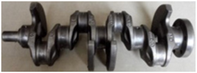
The scrapped crankshaft.
The components and contents of crankshaft material were analyzed using an electron probe (JXA-8230, JEOL, Japan). The main components are Fe, C, and Si as shown in Table 1. Because the crankshafts are generally made by forged steel and nodular cast iron, it is inferred that the crapped crankshaft is made of nodular cast iron for the high C content.31,32
Chemical compositions of the studied nodular cast iron crankshaft (wt%).

Measurement of working surface
Dimensional measurement
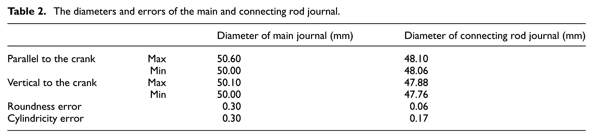
The diameters of the different parts and the circumferential directions of the main and connecting rod journals were measured with vernier calipers, and the maximum and minimum diameters were recorded, as shown in Table 2. It can be seen that the wear thickness of the main journal parallel in direction to the crank is obviously larger than vertical in direction to the crank, and the section of connecting rod journals is slightly elliptical. Also, it can be seen that the local maximum wear thickness is about 0.3 mm, which is far greater than the repair quantity with friction repair method.
The diameters and errors of the main and connecting rod journal.
Hardness measurements
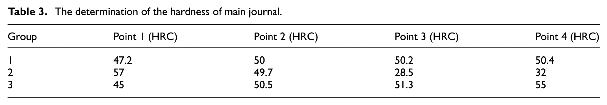
The hardness of the main and connecting rod journal were measured by Rockwell hardness tester (HR-150A, China) with test load of 150 kgf and dwelling time of 5 s. The hardness changes of the main journal are larger than that of the connecting rod journal according to the results of hardness measurements. And, the four hardness values from three groups measured along the main journal in three circumferential directions are shown in Table 3. From Table 3, it can be seen that the hardness range for the main journal is 28.5–57 HRC. However, the difference in hardness of a same crankshaft working surfaces is required no more than 6 HRC in accordance with the literature. 32
The determination of the hardness of main journal.
According to the measurements of diameters and hardness of main and connecting rod journals, it can be deduced that the main journals was more severely and unevenly worn.
Cladding experiment
Preparation of the cladding powders
In line with the performance requirements for the cladding layer, the physical and chemical properties of cladding powders should be similar to the material of the scrapped crankshaft, including melting point, thermal expansion, and cold shrinkage, and should have high wear resistance, corrosion resistance, oxidation resistance, wettability, and so on. In this article, two different types of, Fe-based and Ni-based, alloy powders, which were numbered from 1 to 4, were prepared to perform the cladding experiments. When melt with high temperature in electric melting furnace after the components of materials at a certain proportion ratio mixed well, the Fe-based and Ni-based alloy powders were made by water and nitrogen atomization, respectively, according to the melting point. Finally, the powders were obtained after drying and sieving, and the particles size is 53–198 µm. The components of four alloy powders are shown in Table 4.
Chemical compositions of cladding powder (wt%).

The process of cladding experiment
Design of cladding layer parameters
The thickness of the cladding layer was determined to be 1–2 mm based on the maximum wear thickness of the crankshaft, which would meet the repair requirements for the crankshaft’s abrading section, and the width and length of the cladding layer were set to be 10 and 30 mm, respectively. The path for the cladding processing is denoted via arrows in Figure 2.

The cladding processing path.
Determination of cladding parameters
The ideal microstructure and properties of the cladding layer were determined not only by the alloy powder and the cladding processing route but also by the plasma processing parameters, which include the cladding power, scanning speed, powder feeding rate, distance between the plasma torch and the substrate surface, gas flow, and so on. The coating thickness is not very thick according the plasma cladding technology (the thickness of single layer cladding layer by plasma is generally about 3 mm or 2–3 mm22,25). To obtain the design requirements of a cladding layer with a smooth and uniform thickness, the cladding current, voltage, scanning speed, powder feeding rate, and other parameters were adjusted many times. And, about 2-mm overlap width was formed between the two cladding trace. The final plasma cladding test parameters are obtained and shown in Table 5.
The plasma cladding test parameters.

Figure 3 shows the result of the sample after the cladding process. In the figure, the cladding layer from left to right corresponds to powders No. 1–4. Although there are some obvious overlapping lines, the cladding layers are relatively smooth. Therefore, the experiments process parameters in Table 5 are appropriate.

Samples after the cladding process.
Analysis of the cladding experiment results
Surface hardness of the cladding layer
The hardness of polished surface of the cladding layers is shown in Table 6. The surface of cladding layers of the four powders achieved high hardness, and the Fe-based cladding layer had a higher hardness than the Ni-based cladding layer. Also, the hardness of all cladding layers was higher than the standard hardness requirement for the nodular cast iron crankshaft surface. 32
The surface hardness of cladding layers of the four powders.

Low microstructure analysis of cladding layers
Samples of the cladding layers were cut in the vertical direction with respect to the cladding, after grinding, polishing, and etching by 4% HNO3. The microstructures of the cladding layers were analyzed by means of metallographic microscope (Axio Lab A1, Zeiss, Germany) and shown in Figures 4–7 via low-power microscopy.

The microstructure from powder No. 1: (a) top region, (b) middle region, and (c) adjacent substrate bonding region.

The microstructure from powder No. 2: (a) top region, (b) middle region, and (c) adjacent substrate bonding region.

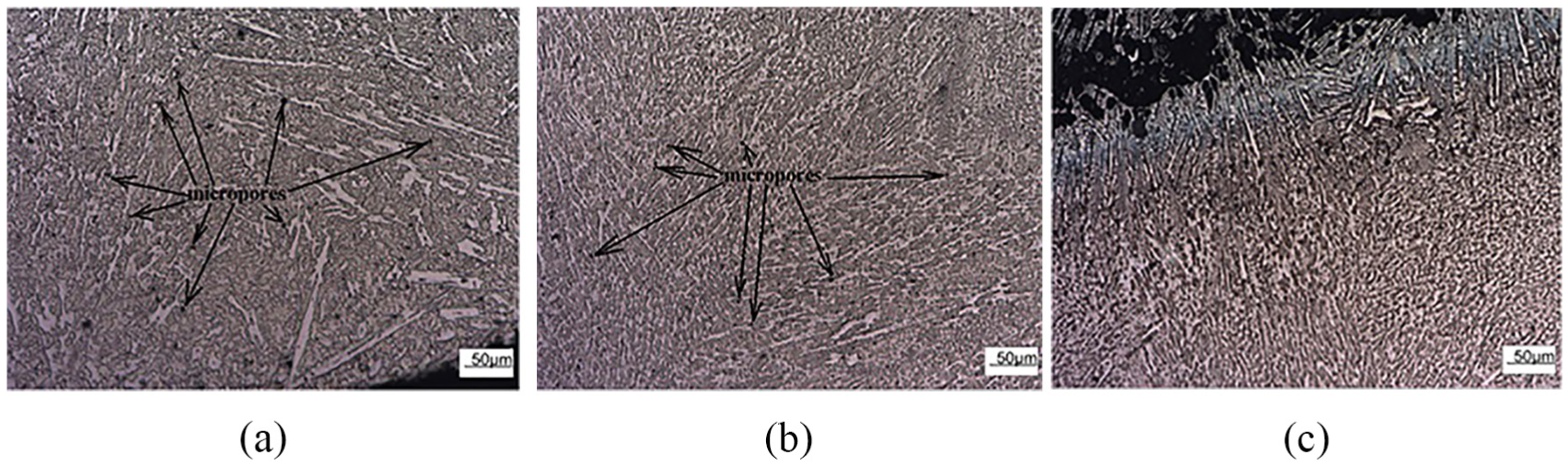
The microstructure from powder No. 3: (a) top region, (b) middle region, and (c) adjacent substrate bonding region.

The microstructure from powder No. 4: (a) top region, (b) middle region, and (c) adjacent substrate bonding region.
Figure 4 shows the microstructure of the cladding layer from powder No. 1. According to the previous research, the entire cladding layer mainly consists of ferrite and eutectic grain boundaries.22,23 The structure of the cladding layer is uniform with a large number of micropores. According to the high hardness of cladding layer, the ferrite is reinforced by a solid solution of a variety of strengthening alloy elements. The main structure of the cladding layer adjacent to bonding region contains dendrites, which formed due to the good thermal conductivity of the nodular cast iron and the high under cooling of the melt powders. There is no obvious interface and there is a lamellar structure in the bonding region, which is due to the diluted substrate and direct crystallization of the cladding layer on the substrate surface.
Figure 5 shows the microstructure of the cladding layer from powder No. 2, which is composed of relatively homogeneous dendrites that have good directivity extended from the adjacent bonding region to the surface of the cladding layer. However, there are a few of microcracks from the higher contents of C and B in powder No. 2, which caused the higher hardness and brittleness of the cladding layer. The structure near the bonding region consists of obvious lamellar eutectic material from the melting of the iron substrate.
Figure 6 shows the microstructure from the cladding layer for powder No. 3, which mainly composed of a Ni-based alloy and carbide according to literature. 20 The microstructure is dense, homogeneous with some tiny micropores and no obvious microcracks. The distribution of carbides in the microstructure is different between the top and adjacent substrate bonding regions. Due to the diffusion of C in the cast iron, the carbides in adjacent middle region form a white reticular structure, and the carbide solid solution of M7(C, B)3 appears as strip-like structures in adjacent substrate bonding regions. 22
Figure 7 shows the microstructure from the cladding layer for powder No. 4, which is also composed of a Ni-based alloy and carbide. The distribution of carbides is relatively uniform and tiny in the middle region and the carbide began to form into thick strips with good wear resistance due to the diffusion of the C into the cast iron in adjacent substrate bonding region. However, there are some micropores that act as the source of the microcracks, resulting in a cladding layer with a lower toughness.
From the above analysis of the cladding layer formed using powders No. 1–4, the microstructures of the cladding layer formed by the two Fe powders are uniform. Because of the alloy element Cr, W, and V solid solution strengthening effect and high content of element B, the hardness is higher, reaching more than 64 HRC. It can conclude that the cladding layer toughness of powder No. 1 is better than that of No. 2. The microstructures of the cladding layer formed by the two Ni powders are also dense and homogeneous. The cladding layer formed by powder No. 4 has obvious microcracks. And, the micropores in the cladding layer formed by powder No. 3 are obviously smaller than the No. 1; therefore, the cladding layer formed by powder No. 3 is more suitable for the surface cladding of nodular cast iron and remanufacturing the working surface of the crankshaft.
High magnification microstructure of cladding layer formed by powder No. 3
The high magnification microstructure of the cladding layer formed by powder No. 3 is shown in Figure 8. There are many micropores with diameters of 3–5 µm in the top region. The diameter of the micropores decreases to about 2 µm in the middle region. Near the adjacent substrate bonding region, the structure is more compact and homogeneous without any micropores, and the strip-like structures is nearly perpendicular to the wear surface with high wear resistance. 22 It implies that in positions closer to the substrate bonding region, the performance increases.

The high magnification microstructure from powder No. 3: (a) top region, (b) middle region, and (c) adjacent substrate bonding region.
As shown in Figure 9, from the rapid increase in the temperature during the cladding process, C atoms diffuse from the high concentration nodular cast iron zone to the alloy layer with a low mass concentration. This caused the spherical graphite in the bonding region to deform to an irregular shape, rather than remaining spherical in the substrate bonding region. In addition, the powder and the substrate metal are melted completely.
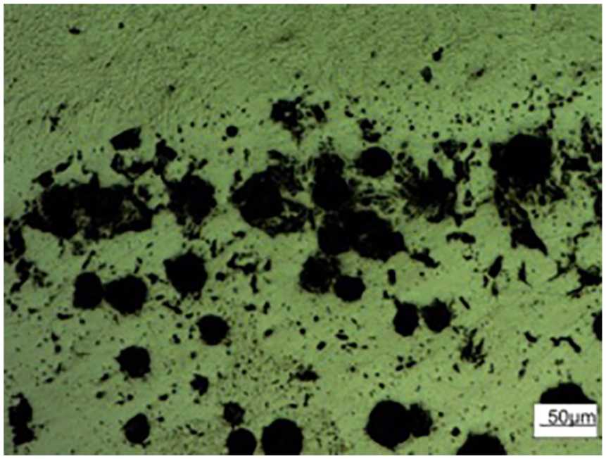
The microstructure of bonding region of cladding layer and substrate layer.
Remanufacturing the main journal
Plasma cladding process for the main journal
The first main journal of the scrapped crankshaft was remanufactured using the plasma cladding process with the parameters corresponding to powder No. 3 in Table 3 at a rotational linear crankshaft velocity of 100 mm/min. The cladded main journal is shown in Figure 10, and the surface of the cladding layer is more continuous and smooth.

The cladded main journal.
Performance of the cladded main journal
Hardness of the cladding layer
After grinding, the cladding layer’s microhardness on the main journal along two random vertical lines from the cladding surface to the substrate was measured by automatic microhardness tester (FM-700/SVDM4R, F-T, Japan) with test load of 10 gf and dwelling time of 10 s, as shown in Figure 11 as line 1 and line 2. A total of 15 microhardnesses were determined at different depths, with 1–12 corresponding to the cladding layer and 13–15 corresponding to the substrate. The hardness of cladding layer ranges from 520–720 HV0.01 (50–60 HRC) is greater than the standard surface requirement for a nodular cast iron crankshaft (because 13–15 measurement points of line 1 are on irregular spheroidal graphite, the hardness of the substrate of the line 1 is lower than that of line 2).

The cladding layer hardness of main journal.
Microstructure analysis of cladding layer of main journal
Figures 12 and 13 represent the low and high magnification microstructures of the main journal’s cladding layer, respectively. Compared with Figure 6, the cladding layer showed in Figure 12 is more dense and homogeneous. The diameters of the micropores are about 3–5 µm and 1–2 µm in the top region of the cladding layer, respectively, in Figures 8 and 13, and the micropores hardly can be seen structure in the adjacent substrate bonding region in Figure 13. The substrate bonding region is more dense and homogeneous in Figure 13. And, the micropores are so small that it hardly affects the practical performance of the crankshaft.
The low magnification microstructure from cladding layer of main journal: (a) top region, (b) middle region, and (c) adjacent substrate bonding region.

The high magnification microstructure from cladding layer of main journal: (a) top region, (b) middle region, and (c) adjacent substrate bonding region.
Conclusion
For the scrapped crankshaft experiencing wear failure, the original working surface dimensions can be obtained by plasma cladding remanufacturing, permitting the crankshaft to have a higher performance than a new one.
The performance of cladding layer was determined not only by the process parameters but also by the degree of matching between the cladding powders and the substrate. In this article, good quality of the cladding layer was achieved using powder No. 3 cladding for a nodular cast iron crankshaft under proper cladding parameters.
For the powder No. 3 cladding remanufacturing of nodular cast iron, the quality of the adjacent bonding region and substrate bonding region in the cladding layer is better than in the top and adjacent top region.
To obtain better quality cladding layers, it is still necessary to adjust the cladding process parameters, powder composition, and cladding thickness according to the amount of wear on the working surface. It is possible that the remanufactured crankshaft will have better performance than the original one.
Footnotes
Acknowledgements
The authors are indebted to Qingdao Haina Plasma Tec. Co., Ltd for supporting the test equipment and to their colleagues for assisting in the process of this study.
Handling Editor: Farzad Ebrahimi
Declaration of conflicting interests
The author(s) declared no potential conflicts of interest with respect to the research, authorship, and/or publication of this article.
Funding
The author(s) disclosed receipt of the following financial support for the research, authorship, and/or publication of this article: This research was supported by the High Educational Institution of Shandong Science and Technology Project (grant no. YB06).