
Abstract
The control of quadrotor equipped with a robotic arm has received growing challenges. This article proposes a new adaptive control strategy of quadrotor equipped with a 2-degree-of-freedom robotic arm. To consider the positional variety of the center of gravity caused by the motion of the robotic arm, the kinematic and dynamic models are built. Based on the presented models, a backstepping and sliding mode controller with a terminal sliding mode manifold is first applied to cope with the condition in which the robotic arm is motionless relative to the quadrotor. As the evolvement of the backstepping and sliding mode controller, a novel adaptive backstepping and sliding mode controller is then designed for the vehicle with the robotic arm wavering. The robustness and effectiveness of the proposed control law are investigated through both simulations and flight tests. With the proposed control laws, several simulations are conducted in conditions of both a variable and a constant center of gravity, and the performance of hovering is tested with a variable center of gravity in an experiment. Overall results show that the proposed adaptive backstepping control could estimate and compensate the variable center of gravity which may seriously influence the stabilization of quadrotor flying in the air.
Introduction
Unmanned aerial vehicles (UAVs), which could hover and move around in three-dimensional Euclidean space, are increasingly used as human assistants in various aspects. They have advantages applying in environments where human assistance cannot reach directly, such as aerial photography, urban search, environmental monitoring, surveillance, and even transportation through the air.
The application field of UAVs becomes more wide today. It is significant for UAVs to equip with a robotic arm to expand its function. The UAVs were aimed at delivering loads in Cruz and Fierro 1 and Faust et al. 2 Similarly, a relatively large object was picked up by two cooperation quadrotors in Caccavale et al. 3 In Gioioso et al. 4 and Wopereis et al., 5 fixed tools on the UAVs were mainly used to impose force on the external environment. All in all, UAVs are skilled in operating with working tools in places where human cannot reach. However, the motion of robotic arms may lead to positional variety of the center of gravity (COG) in the body-fixed coordinate frame. The stabilization of vehicle flying in the air may be seriously influenced by variety of the COG.
To handle this limitation, we should turn to control methods upon UAVs at first. A lot of control strategies on quadrotor have been proposed in recent years due to wide application on various scenarios in our life. Traditional methods on UAV control are based on linear controller design. Proportional–integral–derivative (PID) controller used in Mellinger
6
and Kamel et al.
7
satisfied both position and attitude tracking errors to approach zero ultimately. Furthermore, model linearization was also required in linear quadratic regulator (LQR)
8
and
Afterward, the advanced control strategies are proposed to fit for UAVs equipped with robotic arms recently. In Heredia et al., 18 a stable backstepping-based controller for the UAV that uses the coupled full dynamic model was presented, while an admittance controller for the robotic arm was built. Moreover, a control law able to conduct all the degrees of freedom (DOFs) of the system was proposed in Forte et al. 19 for an aerial manipulator interacting with the environment. In Orsag et al., 20 a combination of gain-scheduling and Lyapunov-based model reference adaptive control was utilized to achieve dynamic stability in a UAV. In addition, the author in Kim et al. 21 designed an adaptive sliding mode controller which was validated with the assumption that the uncertainty caused by modeling error changes slowly. It could be obtained that the UAVs are short of maneuverability under the controller mentioned in Kim et al. 21 All the proposed controllers in this paragraph are based on complete kinematic and dynamic models which consider the UAV and the robotic arm as a combined system. In this article, to consider the quadrotor and the attached robot arm as two independent entities, an adaptive controller is built which could estimate and compensate for dynamical changes in the COG of the UAV in real time. Then the quadrotor would display better maneuverability while reconfiguring in real time when the COG changes.
This paper reports on the design and control of the vehicle with a 2-DOF robotic arm. The kinematic and dynamic models are presented at first considering the robotic arm as an element affecting the COG of the vehicle. Then, a backstepping and sliding mode controller (BSC) with a terminal sliding mode surface is proposed to handle the vehicle accurately on both attitude and position tracking with the COG constant. Afterward, a new adaptive BSC as the evolvement of BSC is designed to cope with the condition in which the COG is variable. Several simulations of the proposed methods have been operated based on the presented model. At first, the BSC is conducted on vehicle to track the expected attitude and position with known COG compared with traditional PID method. Obviously, the PID controller has more delay relative to the performance of BSC on tracking work. Afterward, the adaptive BSC is utilized on vehicle to have an attitude and position tracking contrast to the BSC in condition of variable COG. Moreover, the experiment is conducted to test the stabilization performance of vehicle hovering in the air under both BSC and adaptive BSC with robotic arm moving. The results of simulation and experiment show that the adaptive BSC outclasses the strategy of BSC in condition of variable COG.
The organization of this article is described as follows. In the next section, the kinematic and dynamic models of the vehicle with variable COG are presented. Then the BSC and adaptive BSC for the whole system are proposed. The latter two sections present the results of simulation and experiment, respectively. Conclusions are drawn in the end of this article.
Kinematic and dynamic model
Four propellers, which could produce four lift forces as the real control inputs to the system, are fixed on the quadrotor, as described in Figure 1. The lift forces could be controlled by adjusting the speeds of propellers. However, the quadrotor is an under-actuated system with 6 DOFs. In that case, various motions could be created by changing the speeds of propellers. Roll rotation coupled with lateral motion could be produced by varying the speeds of second and fourth propellers. Similarly, changing the speeds of first and third propellers would lead to pitch rotation and its matching lateral motion. Yaw rotation is generated through changing the difference of counter torque between the two pairs of propellers (1,3) and (2,4). Afterward, the kinematic and dynamic model of the quadrotor combined with a 2-DOF robotic arm is presented.
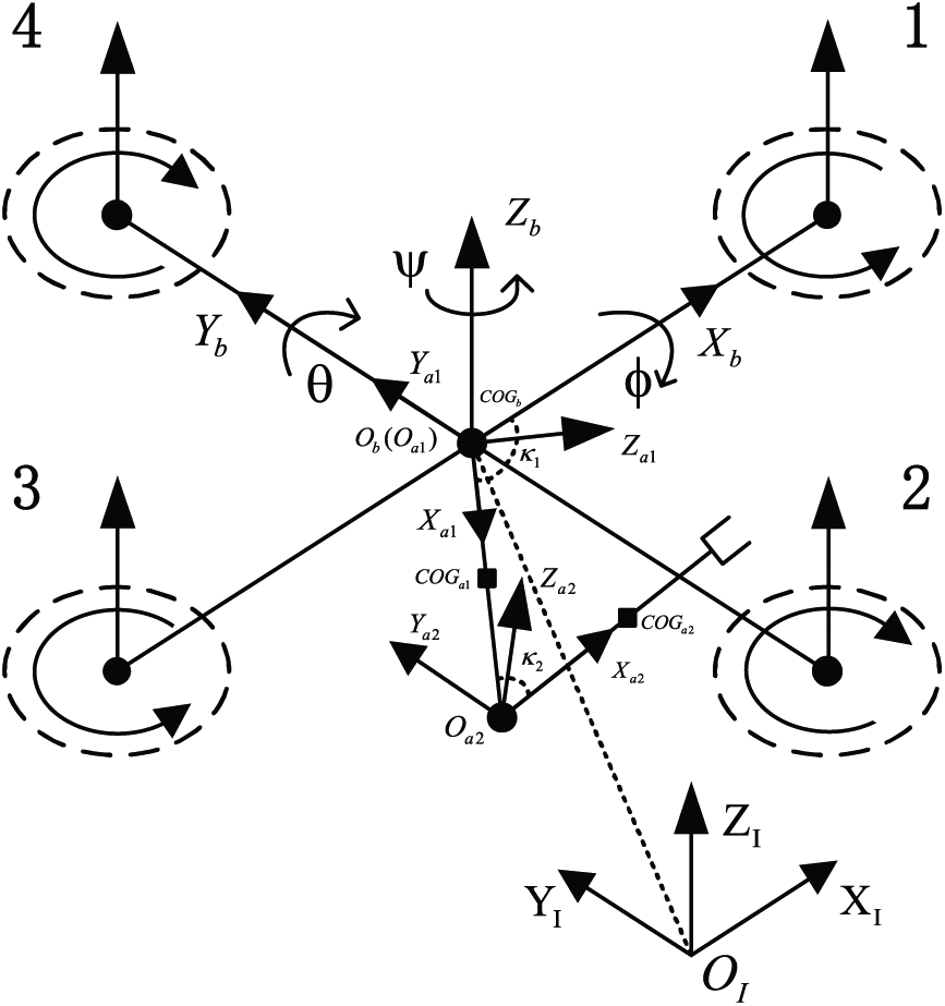
Quadrotor and robotic arm system with coordinate reference frames.
Kinematics for the vehicle
As shown in Figure 1, several coordinates are defined as follows:
The joint angles of the robotic arm are described by

where


where c(*) and s(*) mentioned above represent the abbreviations of cos(*) and sin(*), respectively.
As shown in Figure 1, there is a 2-DOF robotic arm fixed on the quadrotor whose motion may vary the COG of the vehicle. The equation about the actual location of COG in vehicle could be obtained by combining the COG of both quadrotor and the robotic arm

The meanings of parameters in equation (4) are shown in Table 1.
Parameters in equation (4).

COG: center of gravity.
Dynamics for the vehicle
Traditional dynamic model of a quadrotor with a constant COG in the geometrical center could simplify model equations. However, along with the robotic arm moving, the COG in the quadrotor will change. Referring to Sagatun and Fossen, 22 the dynamic model of the whole system is built in this section.
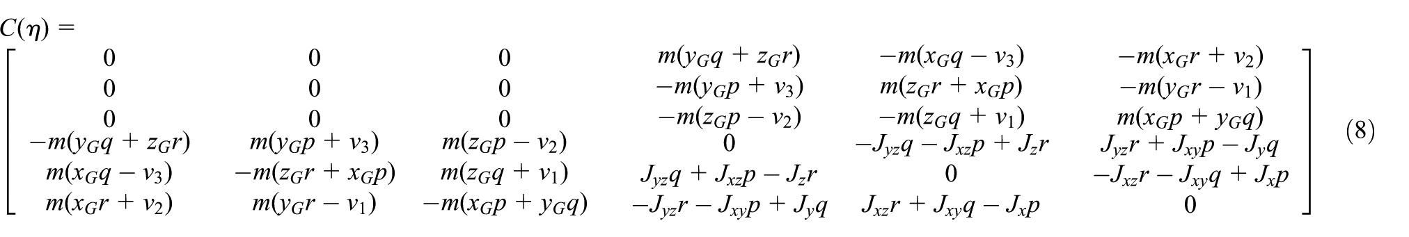
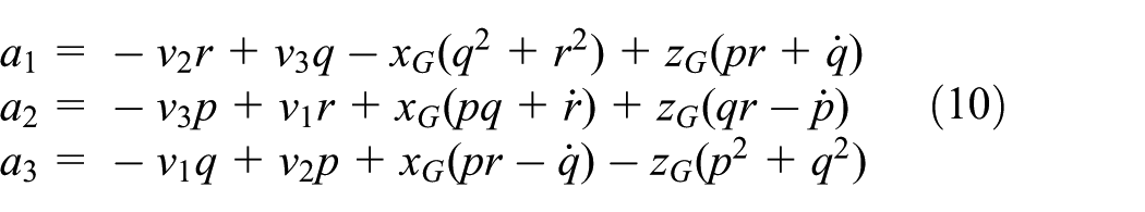
We separate the quadrotor and the robotic arm which is considered as an element causing the COG to be displaced from the geometric center of the vehicle when building the dynamic model. Then the equations of motion for vehicle could be obtained as follows

where the vector of linear and angular velocities is represented by

where lift force along

where
where the product of inertia of the vehicle based on its symmetrical structure could be defined as

where


where
Controller design
The vehicle being an under-actuated system with four control inputs and 6 DOFs is difficult to have a controller to perfection. A control scheme shown in Figure 2 has been proposed to bring about a better performance. There is a cascaded control system comprising of two main control loops named position control and attitude control in the whole control block diagram. The desired attitudes are generated by the position control loop which is built out of the attitude control loop. The attitude controller, which serves as the inner control loop to force the attitudes to track the desired orientations asymptotically, is very significant to the stabilization of vehicle.

Control scheme of the vehicle equipped with a 2-DOF robotic arm, where “Several Parameters" mentioned in the picture mainly contains the translational velocity, acceleration and angular velocity of the vehicle, and so on.
Position control
The position controller is designed to accomplish the tracking from the actual position to the desired destination. However, it is incapable of driving the vehicle directly being an outer control loop. The desired roll and pitch attitude could be got from the position controller


Attitude control
BSC
In this section, a backstepping approach is conducted to start the control process at the origin of the whole system at first. Afterward, based on the former step, a sliding mode controller equipped with a terminal sliding mode surface is built for the vehicle referring to Xiong and Zhang. 14 The vehicle could approach the state of stabilization in seconds under the proposed control strategies.
Backstepping control
Using the backstepping approach, the system could be forced to follow the desired trajectory by synthesizing the control law.
We define the roll angle tracking error at first

For the second step, we consider the Lyapunov function positive definite as follows

Its derivative with respect to time which is negative semi-definite

In addition, defining


where
In that case, we derive

Sliding mode control
The terminal sliding mode surface, which permits us the synthesis of stabilizing control law, is chosen based on the synthesized tracking error. It is defined as

where
We consider the Lyapunov function

Differentiate it with respect to time
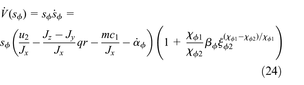
To synthesize a stabilizing control law by sliding mode, the sliding condition

where
It could be obtained on condition that equation (25) is satisfied

Consequently,

Similarly, we could obtain
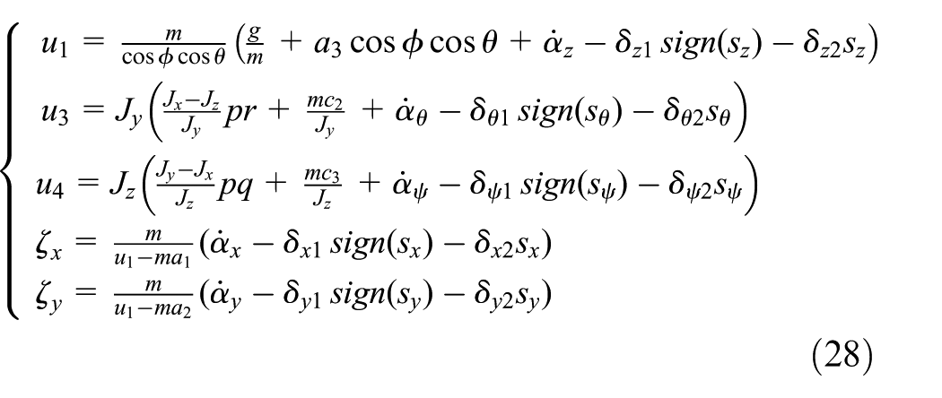
where
Adaptive BSC considering the variety of COG
The control method proposed in previous section may work on condition that the robotic arm is motionless all the way. However, the motion of the robotic arm equipped on the quadrotor may lead to the variety of COG in the vehicle. In that case, the presented control method will not work. Therefore, we propose a COG adaptation law to address this problem. As shown in Figure 2, the module of adaptive controller is capable of estimating the COG in real time and compensates it afterward.
First, we define estimation error

where
For the second step, the augmented Lyapunov function is defined as

Differentiate it with respect to time

We define the COG adaptation law as
In that case, equation (31) becomes

Being similar to the principle proposed in last section, we define

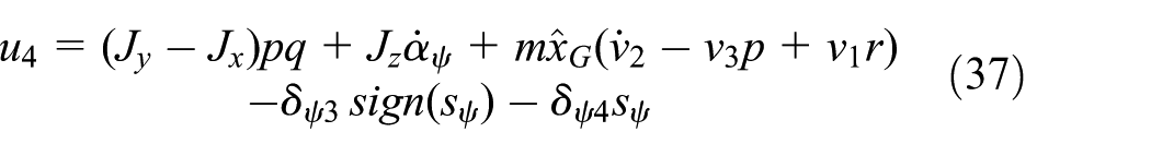
Afterward, equation (33) could be obtained

The system is stable with respect to the theory of Lyapunov stability.
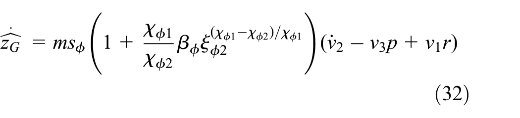
Similarly, the estimated COG in x-axis could be obtained

Then, the
Simulation
In this section, simulations under constant and variable COG have been conducted based on MATLAB/SIMULINK to confirm the validity of the proposed control scheme. Meanwhile, the full dynamic model of the vehicle with a robotic arm is built in the simulation. The chief parameters used above are listed in Table 2.
Chief simulation parameters of the vehicle.

With the COG constant
Attitude tracking
An effective attitude tracking is the foundation of quadrotor motion. Serving as the inner control loop, it is the prerequisite of the others. The simulations with the proposed dynamic model on attitude tracking with PID control strategy and BSC have been conducted as shown in Figures 3 and 4, respectively. The initial

Tracking the desired attitude using PID control strategy.

Tracking the desired attitude using BSC.
Flying to desired position
It is beneficial for vehicle to have an exact position tracking so as to accomplish some assignments from its master, such as aerial photography with high accuracy, person following-up. The simulations upon position tracking using PID and BSC control strategy are shown in Figures 5 and 6, respectively. The initial position is (0,0,0), and the desired position is (12,5,8). Obviously, the vehicle controlled by BSC approaches the destination in shorter time than that under PID strategy. Meanwhile, it overshoots the target about 0.15 m along x-axis using PID, while the trajectory under control of BSC could accomplish the process with no overshoot.

Flying to desired position using PID control strategy.

Flying to desired position using BSC.
With the COG variable
The simulation provided before indicates that the BSC performs much better than PID on both attitude and position tracking with COG constant. Furthermore, it has been proved that PID could barely cope with the condition with variable COG. In this section, the BSC and adaptive BSC are implemented for comparison.
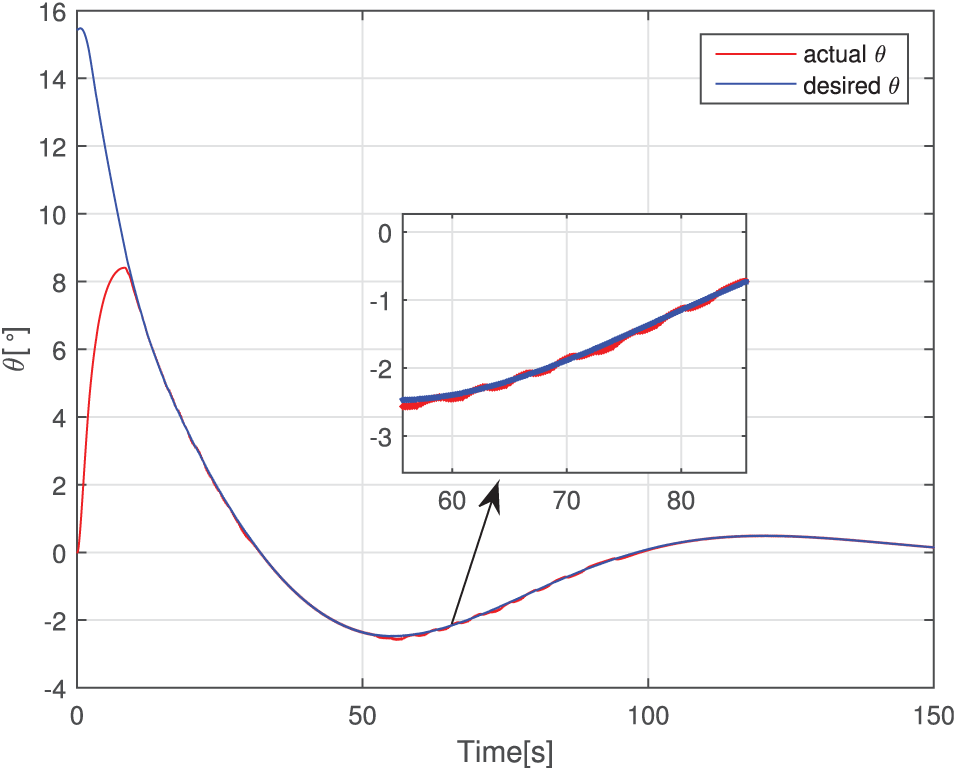
Attitude tracking
There are two phases in this simulation process. The vehicle follows the desired attitude at first phase lasting 50 s with the COG constant. However, the vehicle in the second phase from 50 to 100 s is provided a variable COG to verify the feasibility of proposed control strategy. As shown in Figure 7, the

Tracking the desired
Tracking the desired
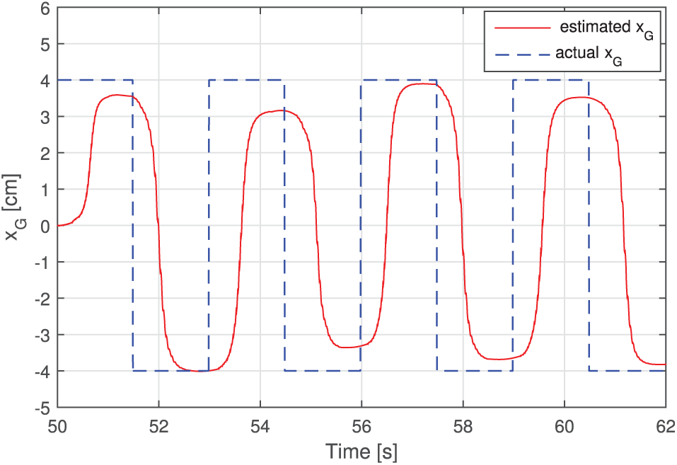
Estimated
Position tracking
In this section, the variable

Tracking the desired trajectory using BSC with variable COG.
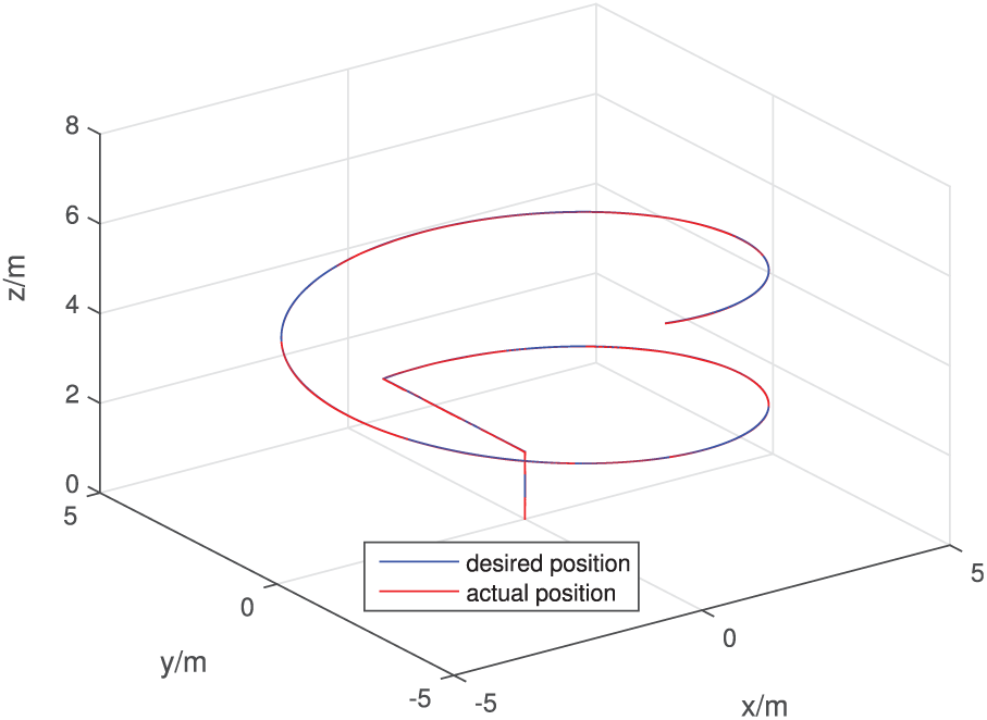
Tracking the desired trajectory using adaptive BSC with variable COG.

Estimated
Experiment
Using the proposed control strategies, the experimental flight test has been conducted in the playground. As shown in Figure 13, the quadrotor and robotic arm are the two main parts of the vehicle. The robotic arm is fixed at the center of the belly in vehicle. The quadrotor, whose gross weight is 1360 g, consists of airframe, controller, sensors, propellers, and battery. The robotic arm is weighed 410 g totally including three steering engines and a gripper of manipulator.
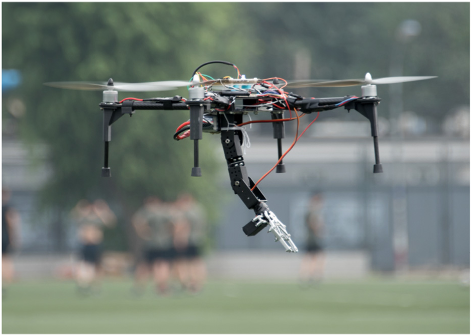
Flight test with robotic arm.
The robotic arm is moved while the vehicle is hovering in the air to test the stabilization performance of the proposed BSC and adaptive BSC, respectively. The robotic arm is manipulated to move from vertical position to a slant one at 20.75 s. Its motion leads to the variety of COG. The BSC is conducted for test at first with the variable COG. Then the adaptive BSC is performed as a contrast. The flight data of vehicle under control of BSC and adaptive BSC are stored in CD card at a frequency of 40 Hz. Thereinto, the
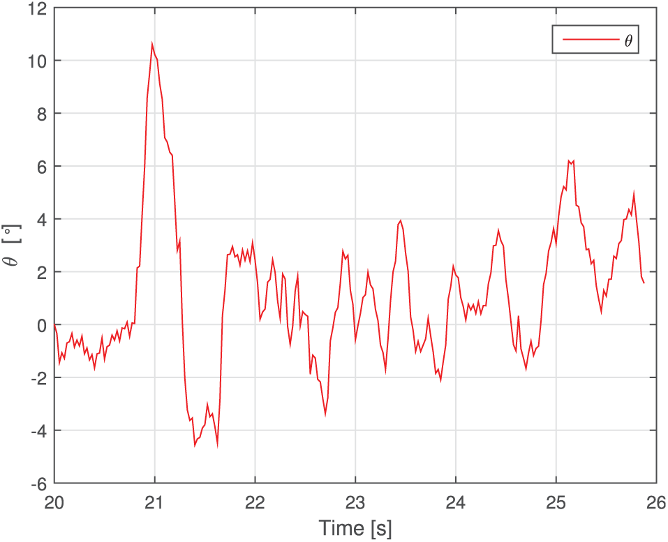
Flight test of stabilization using BSC with variable COG.

Flight test of stabilization using adaptive BSC with variable COG.
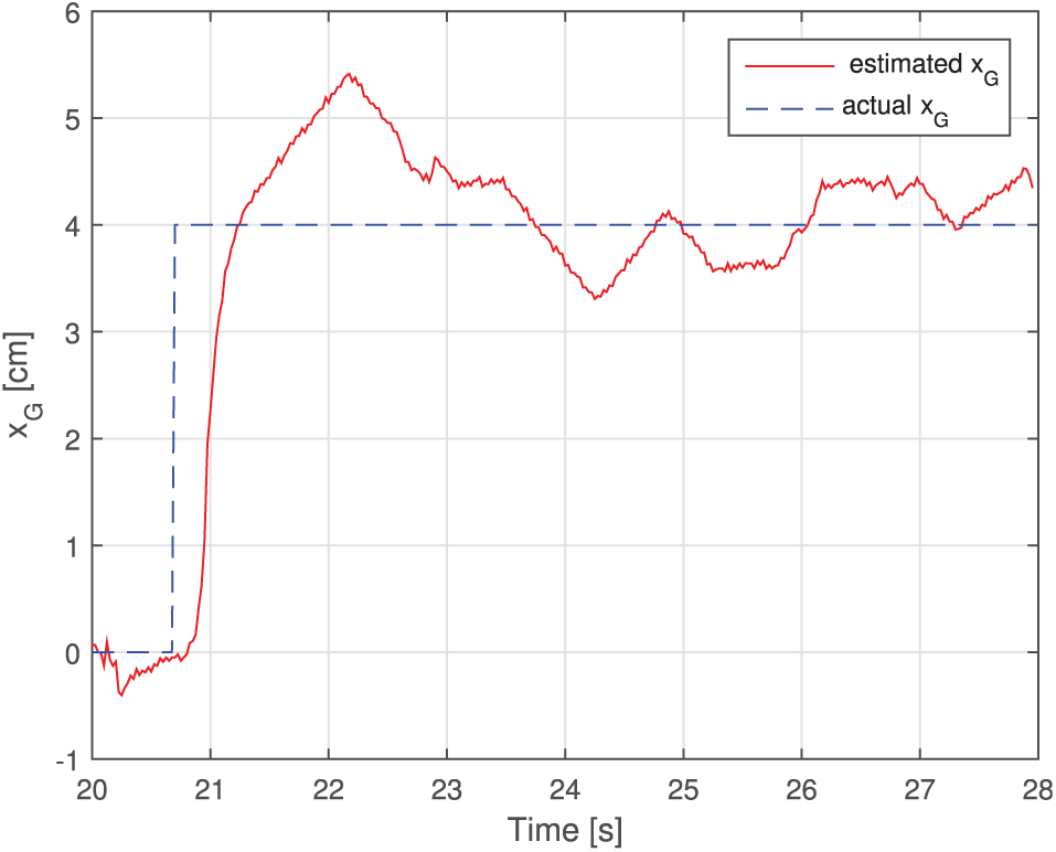
Estimated
Obviously, the adaptive BSC performs much better than BSC to cope with variable COG in the experiment. The oscillation under control of adaptive BSC is twice less than the one under BSC. Furthermore, using adaptive BSC, the vehicle will be stable in seconds with
Conclusion
This article deals with a quadrotor with a 2-DOF robotic arm. Kinematic and dynamic models are built considering the robotic arm as an element leading to the variety of the COG. An adaptive control strategy is proposed to optimize the performance of tracking and stabilization of a quadrotor with the robotic arm moving in the flight. The robustness and effectiveness of the presented control method have been demonstrated in both simulation and experiment.
Footnotes
Handling Editor: Jose Antonio Tenreiro Machado
Author note
Mingjie Dong is now affiliated to School of Mechanical Engineering and Applied Electronics Technology, Beijing University of Technology, Beijing, P.R. China.
Declaration of conflicting interests
The author(s) declared no potential conflicts of interest with respect to the research, authorship, and/or publication of this article.
Funding
The author(s) disclosed receipt of the following financial support for the research, authorship, and/or publication of this article: This work was supported by the National Natural Science Foundation of China under grant no. 61633002.