
Abstract
A continuum robot was designed to assist aircraft crew in inspecting fuel tanks, thereby decreasing the workload of fuel tank inspection and improving the efficiency of maintenance. The Rzeppa universal joint and cylindrical helical spring were taken as the joint section of the main body, and the load capacity of continuum robot had been improved greatly. Based on the isokinetic feature of the Rzeppa universal joint, the single-section kinematic analysis of the continuum robot was conducted according to the unit load method of cylindrical helical spring. Next, the influence of variable curvature bending properties of the plant was reduced, and the mapping relationship among the end position, joint variables, and the length of driving cables was obtained. Finally, the simulation and prototype experiments were performed, and the results proved the strong loading capacity of the continuum robot and the effectiveness of the kinematic model.
Introduction
The aircraft fuel tank is an important part of an aircraft. With corrosion and bumps over a long period of time, leaks or cracks may appear in an aircraft fuel tank; these leaks and cracks are important factors that can lead to air crash according to the air disaster histories.1,2 Hence, it is of vital importance to inspect and maintain the fuel tank of an aircraft. As shown in Figure 1, the fuel tank examination is usually performed manually to identify the leak or corrosion location, and the crewmember must enter the tank to perform this task. It is a cumbersome and time-consuming task, with the restricted environment containing high-concentration oil and gas being harmful to human health. 3

Aircraft fuel tank inspection.
The use of a routine auxiliary inspection system cannot easily accomplish this task because of its structural limitations. Compared with the traditional discrete robot, the continuum robot has the advantages of a larger length–diameter ratio, more freedom, and flexible movement, making it well suited for those complex environments. Thus, our project group designed an aircraft fuel tank inspection robot (AFTIR) with a continuous structure to assist the crew during the inspection of a fuel tank.
Several scientific research institutions have engaged in related research of continuum robots. The OctArm robot consisted of high-strain extensor air muscles, called McKibben actuators, and its movements were controlled by both air pressure and actuators.4,5 Considering the effect of material nonlinearities, as well as distributed weight and payload, D Trivedi 6 presented an approach for modeling soft robot manipulators on the platform of OctArm V. The model was established based on the general Cosserat theory of rods and a fiber-reinforced model of air muscle actuators. A spring–damper system model was proposed on the OctArm VI platform. The model assumed that the mass of each drive of the robot was concentrated in the center of mass, and the Lagrangian dynamics principle was used to derive the generalized force expression of the system.7,8 However, considering the fact that the robot carried too many electronic devices and the pneumatic drive was adopted in the OctArm series, the robot structure is not suitable for tank inspection in the constrained space.
Based on the Cosserat rod and Cosserat string models, as well as the condition of external load, the static and dynamic coupling models of the continuum robot were derived. 9 However, this coupled model derivation process was complex because strong coupling and distortion would be produced easily. Considering several influencing factors, such as the effects of inertia, driving, friction, elasticity, and gravity, a type of variable curvature motion model based on the principle of virtual power was presented. 10 However, this model is not suitable for practical applications because it neglected the payload.
In a continuum robot, plastic springs made of styrene maleic anhydride (SMA) were used to link the robot sections, making it suitable for brain surgery.11,12 It assumed that all curvatures were equal, and it determined the single-joint cable length variation using the trigonometric function theorem and the kinematic model with the Denavit–Hartenberg (D-H) matrix. However, the spring gravity was ignored, making the curvature of the joint bending variable. This method increased the error; as a result, it is not applicable to the design of the structure in this article.
There are several relevant agencies studying the application of a continuum robot in the inspection of an aircraft fuel tank. One such robot was composed of rigid links and equipped with braking devices and encoders (to provide feedback on the rotation angle), and its joints were driven by motors. Its kinematic model was obtained based on the D-H method;13,14 however, its weight was large, making it inconvenient for inspecting an aircraft fuel tank. Continuum AFTIRs were studied in our laboratory. The mapping relationship among the joint variables, driving cable length variation, and the end position was established based on the curvature projection method.15–17 However, the load capacity of the mechanical structure was insufficient, making the robot unsuitable for practical applications.
At present, the continuous robots are usually driven by an air pressure driving system or a line driving system, and the structure is primarily composed of artificial muscles, flexible braces, or joint hinges. Such structures often have the disadvantage of insufficient load capacity. The constant curvature bending model is used to simulate the construction of the kinematic model; however, this does not conform to the circumstances of the real environment. The inspection of an aircraft fuel tank requires the robot to have a strong load capacity. Under the influence of the gravity, the shape of the robot is a variable curvature.
Considering the characteristics of an aircraft fuel tank and the tank inspection requirements, a continuum robot was designed based on the Rzeppa universal joint to enhance load capacity. Based on the isokinetic feature of the Rzeppa universal joint, 18 the single-joint kinematic analysis of continuum robot was conducted according to the unit load method of a cylinder spiral spring.19,20 A variable curvature model was established to account for the influence of the load and the changing curvature of the structure; as a result, the control precision is improved.
The structure of this article is as follows. Section “Structure design” describes the structure of the robot. Section “Basic framework of the kinematic analysis” presents the basic framework of the kinematic analysis. Section “Kinematic analysis” illustrates the mechanical analysis of the continuum robot. Section “Mechanical analysis” derives the continuum robot kinematics. The simulation and experimental results are provided in section “Experiments and result analysis.” The conclusions are summarized in section “Conclusion.”
Structure design
A continuum robot is a new type of bionic robot. Such a robot can adapt to nonstructural, confined, and complex environments flexibly. As shown in Figure 2, the flexible continuum robot can enter the interior of the fuel tank with a detector for inspection, and the rigid linear module can provide telescopic movement of the snake arm. Considering the characteristics of the continuum robot, it can be used to assist the crew in inspecting an aircraft fuel tank.

Schematic diagrams of (a) the robot and (b) the operation in an aircraft fuel tank.
Referring to the structural characteristics and movement mechanism of snake vertebrae, the single-joint continuum robot is designed. The robot consists of the driving module, the continuum structure, and the control module. In the driving module, three cables are used to control the continuum structure. The single joint in the continuum robot consists of the Rzeppa universal joints, end disk, support disks, base disk, and cylindrical helical springs. The single joint consists of eight spring sections and can perform bending and rotating motions, as shown in Figure 3.

Structure of the continuum robot.
The Rzeppa universal joint is mainly composed of the foundation, outer race, steel ball, and driving shaft. The structure of the joint is similar to that of a snake vertebrae spherical hinge socket and spherical head, as shown in Figure 4. Rzeppa universal joints in the continuum robot enhance the load capacity of the robot. A Rzeppa universal joint has the isokinetic feature because the transfer point is always at the intersection plane of two axes. This characteristic makes the joint significantly different from ordinary joints. This characteristic ensures the flexibility of the robot, and the bending and rotational motions are also decoupled.
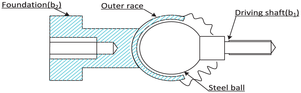
Structure of Rzeppa universal joint.
Because the Rzeppa universal joint lacks the ability to restore itself, the cylindrical helical spring is adopted to supply the recoverable force. The parameters of the spring can be determined by the load.
The robot realizes bending and rotation by changing the length of the three cables. The attachment points of the three driving cables are symmetrically arranged at 120° on both disks.
Basic framework of the kinematic analysis
The AFTIR moves by changing the lengths of the cables, and the attitude of the robot is related to spring deformation and the Rzeppa universal joint morphology. Thus, there exists a relationship among the end positions, joint variables, and the length of driving cables, as shown in Figure 5. Kinematic analysis of the single joint of a continuum robot includes two transformations: (1) the mapping relationship between the end position

Kinematic relation model of a single joint segment.
Kinematic analysis
Different deformations of the spring section lead to different postures of a single joint. Because of the effect of gravity on the robot, the posture is shown as a variable curvature curve. Thus, the driving cables show the form of a polygonal line. Based on the global mechanical analysis and partial mechanical analysis of the robot, the joint variables and the spring section variables are deduced and the length of the driving copes can be deduced by substituting the spring section variables into the spring broken line model. Next, the length of the cables
The kinematic analysis of a single spring section is presented, as shown in Figure 6.

Kinematic bending model of a single spring section.
In this figure,
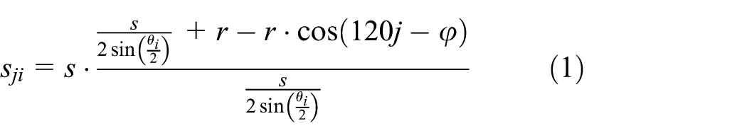
The

Mechanical analysis
Each joint segment consists of eight spring sections, each of which is rigidly linked. The attitude of a single joint section and the spring is consistent; thus, mechanical analysis is conducted only for the spring. The robot’s movement is variable curvature because of the effect of gravity on the Rzeppa universal joints, springs, and load. In this article, the global mechanical analysis and partial mechanical analysis of a single joint segment are performed to obtain the mapping relationship among the end position, joint variables, and spring section variables.
Global mechanical analysis
Regarding single joint segment as a whole, when the spring is bending, it may be subjected to axial load
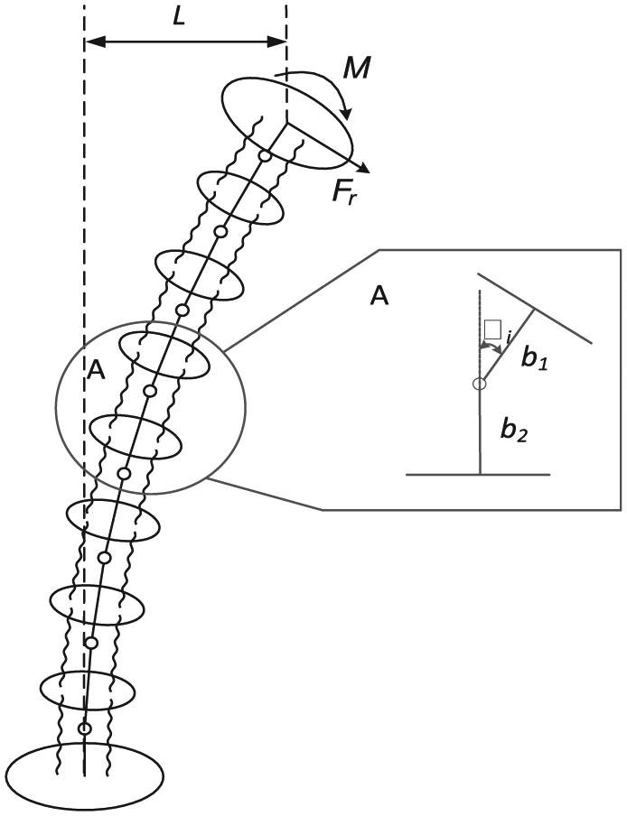
Global mechanical analysis of a joint.
The unit load method of the spring is used to analyze the effect of the bending moment. The stress of an arbitrary spring section is approximately equal based on the Mohr strength theory. The bending moment and the torque action are shown in Figure 8. The t-axis is consistent with the tangent of the spring cross-section centerline. The n-axis is consistent with the normal of the spring cross-section centerline, which points to the center of the cylindrical helical spring. The b-axis represents the binormal of the spring cross-section centerline, which conforms to the right-hand rule with the n- and t-axis.

Stress of an arbitrary spring section.
The deformation formula of a single joint can be obtained by integrating the bending moments and torque of the spring section, as shown in formula (3)

where lm represents the spring offset caused by the bending moment
Formula (4) can be obtained from Figure 7

To facilitate the kinematic calculation, we must obtain the relationship between the bending angle and the offset of a single joint; thus, spring micro-segments can be indicated by the spring helix polar angle (δ) as follows

where D represents the spring pitch diameter, α represents the spring helix angle, and d represents the spring cable diameter. According to formulas (3)–(5), the minor integrals are omitted; thus, formula (6) is obtained as follows
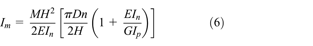
where n represents the effective cycle number of the spring.
According to the spring characteristic parameters, formula (7) can be obtained as follows

where
When the spring is subjected to the radial force
where
The integral result of H is shown in formula (10)

Finally, the overall offset L can be obtained by the sum of the bending moment M and the radial force Fr; the formula is as follows

Partial mechanical analysis
According to the principle of conservation and conduction of the bending moment, the spring section has the same bending moment and the same radial force caused by the cables. The moment and radial force are caused by the force of gravity on all the above devices. The offset formula of the spring section is as follows
Formula (13) shows the definitions of the parameters

Thus, formula (12) can be simplified as

Finally, we can obtain the mechanical offset relationship matrix; the formula is as follows

From the above formulas (2)–(14), the spring section variables
Setting the center of the base disk as the origin of the robot


Experiments and result analysis
To verify the kinematic model described above, experiments including data simulation analysis and prototype experiments were conducted.
Data simulation analysis
According to the structure and the materials of the continuum robot, the relevant parameters are determined, as shown in Table 1. Through formulas (6) and (8), the relationships of the bending moment
Continuum structure and device material parameters.


Analysis of the bending moment
It can be seen from Figure 9 that the bending moment
The relationship between the length variation of the driving cables and the bending angle.

The relationship between the length variation of the driving cables and the rotation angle.
Figure 12 shows the simulation results of the mapping relation between the joint variables and the end positions based on the kinematic mode. The single segment length is L = 352 mm. The bending angle range is

The relationship between the length variation of the driving cables and the rotation angle.
Prototype experimental analysis
The validity and practicability of the kinematic model were verified by data analysis. The prototype experiment of the continuum AFTIR had a single joint manipulator. A single joint consists of two degrees of freedom. The range of the bending angle is
Single-joint no-load bending test: (a) θ = 45° and φ = 0°; (b) θ = 120° and φ = 150°; (c) θ = 90° and φ = 210°.

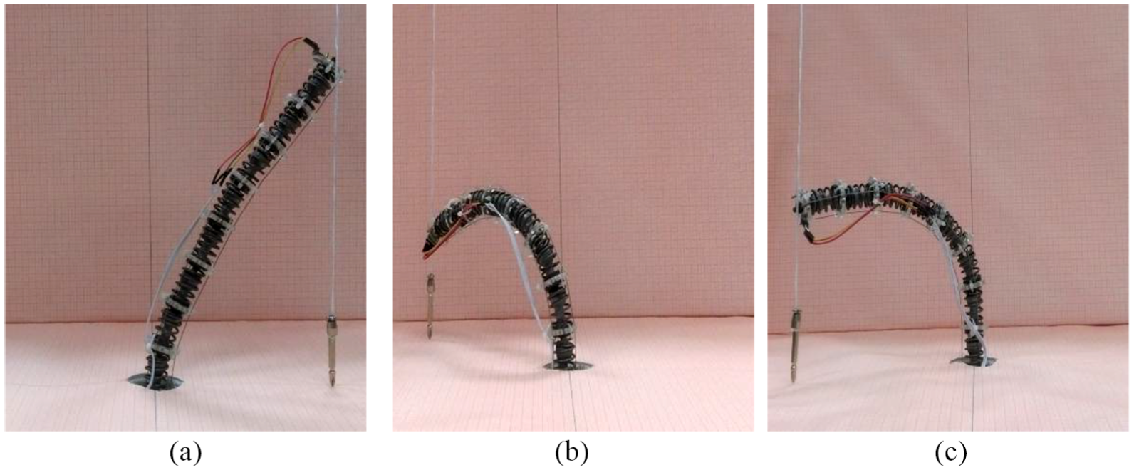
Single-joint load bending test: (a) θ = 45° and φ = 0°; (b) θ = 120° and φ = 150°; (c) θ = 90° and φ = 210°.
According to the three postures of the manipulator, error analysis was conducted. The comparison information includes the end position information, bending angle, and rotational angle. Finally, the comparison error

In formula (17),
Position data error analysis.

Attitude data error analysis.

In Table 2,
The analysis of data from Tables 2 and 3 provided the following results: (1) The relative errors of the end position are less than 3%. The relative errors of the bending and rotational angles are both less than 6°. The bending angle error increases as the bending angle increases. The results validated the kinematic model based on force analysis and geometric model analysis. (2) From the comparison experiments with and without load, it obvious that the errors of the position and the angles in load experiments are slightly larger than the errors of the position and the angles of the no-load experiments. The maximum angle errors of the load experiment are less than 6°. The results verified that the continuum robot of this structure has a load capacity.
Conclusion
In this article, a continuum robot was designed to assist aircraft crew during the inspection of a fuel tank; the use of this robot can decrease the workload of fuel tank inspection and improve the efficiency of maintenance. A Rzeppa universal joint and cylindrical helical spring were adopted in the robot. The prototype experiments showed that the robot had strong load capacity and practicability. To improve the rapidness and accuracy of the control, the cylindrical helical spring unit load method was used to analyze the spring force, and the kinematic model of the single-joint manipulator was obtained. The prototype experiments showed that the robot had high control accuracy, thus verifying the kinematic model’s effectiveness. Compared with other existing models, the model presented in this article takes into account the effects of load and variable curvature.
Footnotes
Acknowledgements
The authors would like to thank their colleagues at the Robotics Institute of Civil Aviation University of China for their significant contributions.
Handling Editor: Xiang Yu
Declaration of conflicting interests
The author(s) declared no potential conflicts of interest with respect to the research, authorship, and/or publication of this article.
Funding
The author(s) disclosed receipt of the following financial support for the research, authorship, and/or publication of this article: This work was funded by the Tianjin Research Program of Application Foundation and Advanced Technology (#14JCQNJC04400).