
Abstract
Detent force is an important factor affecting the running of permanent magnet suspension belt conveyor. Specific to detent force characteristics of the permanent magnet suspension belt conveyor, a finite element method was adopted to perform finite element analysis on a permanent magnet support system based on diverse air gaps, parameters of permanent magnets, and different kinds of clearances between permanent magnets. Not only was a method of defining the optimal buoyancy–resistance ratio for the permanent magnet suspension belt conveyor presented but also an optimized mathematical model for buoyancy–resistance ratio that takes velocity into account was established. Furthermore, a global optimal solution
Introduction
Traditional belt conveyors rely on not only idlers to support the conveyor belt and materials but also on frictional force between driving pulley and the conveyor belt to realize continuous transport of materials. In addition, speed of such conveyors is usually below 6 m/s. 1 In the running process, sag resistance and frictional force between the carrier roller and the conveyor belt consume significant energies together with roller revolving resistance. According to statistics, energy losses related to the carrier roller take 70% in the total energy consumption of the entire conveyor system.2,3
Based on a magnetic mechanical technique, non-contact suspension support of the permanent magnet suspension belt conveyor is implemented by virtue of repulsive forces between the permanent magnet and the magnetic belt. In this manner, detent force turns into the major running resistance, which makes it possible for belt conveyors to run at a high speed.4,5 The permanent magnet suspension belt conveyor is still in the preliminary theoretical research stage, and existing research is limited to the design concept of magnetic levitation conveying technology. In 1972, the former Soviet Union developed a magnetic friction conveyor. 6 Researchers at the University of Manchester in England developed a conveyor that used a linear induction motor. Japan, South Korea and Italy also carried out basic research and prototype design of various types of magnetic suspension transport machinery.7–9 Fang 10 analyzed the research value, working principle, and technical performance of the magnetic cushion belt conveyor; designed the overall structure; and carried out the finite element simulation study on the electromagnetic field. Cheng and Wang 11 and Hu et al. 12 separately compared electromagnetic levitation support and permanent magnetic levitation, analyzed air gap characteristics, and put forward a deviation control strategy. Considering that studies on detent forces are still not reported publicly, it is necessary to carry out in-depth research on detent force that serves as an important parameter for permanent magnet suspension belt conveyor design.
Detent force is a parameter that shows the running resistance of the permanent magnet suspension system and can be influenced by air gaps, permanent magnetic materials, and clearance between permanent magnets. With the finite element analysis method used, this article seeks to explore the law of change of the detent force under the influence of the above factors as belt velocity changes and provide a basis for the design of permanent magnet suspension system structure size and for the parameter selection of the permanent magnets. Buoyancy–resistance ratio is an important parameter of the operating performance of the permanent magnet suspension system. If the buoyancy-resistance reaches the maximum, the permanent magnet suspension belt conveyor works most efficiently.
In this article, a mathematical model of buoyancy–resistance ratio is established, and the velocity optimization of the buoyancy–resistance ratio is discussed, which can be used as reference for the optimal operation parameter setting of the permanent magnet suspension system.
Structure of permanent magnet suspension belt conveyor
This study on the detent force of a permanent magnet suspension belt conveyor was conducted based on a structure proposed by this research group (Figure 1). Dependent on the repulsive force between a static permanent magnet and a magnetic belt, non-contact suspension support was realized. In addition, the driving force provided by the friction between anti-magnetic driving pulley and the magnetic belt was matched with anti-magnetic bend pulley and anti-magnetic return idler to fulfill continuous material transfer. A mechanical model of the permanent magnet suspension belt conveyor is given in Figure 2. According to this figure, certain air gaps exist between the upper magnetic belt and the lower rectangular permanent magnets with equal clearances; and the permanent magnet is static. In a stabilized condition, the magnetic belt moves uniformly along the direction of y+ axis; as a result, relative motion inside it gives rise to induced eddy flows and the interaction of eddy current and permanent magnet’s magnetic fields further generates a levitation force, a detent force, and a lateral force acting on the magnetic belt.
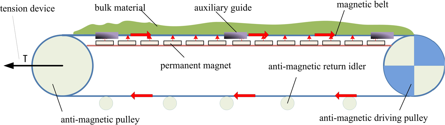
Structure diagram of a permanent magnet suspension belt conveyor.

Simplified mechanical model of a permanent magnet suspension belt conveyor.
Finite element analysis
To guarantee stable running of a permanent magnet suspension belt conveyor, magnetic levitation vehicles should be precisely designed and computed. At this stage, computing of magnetic machines principally takes advantage of a magnetic circuit method–based analytic approach and a numerical method (finite element method (FEM)). As to the magnetic circuit method, it is a simplified algorithm with limitations and fails to accurately figure out magnetic flux leakage and magnetic resistance or reveal strong nonlinearity characteristics of magnetic materials. 13 In comparison, a problem of magnetic field calculation boils down to obtaining a partial differential equation by virtue of given boundary conditions, loading conditions, and various constraints as far as FEM is concerned. In addition, on the basis of modern mathematical and mechanical theories, FEM adopts computer technology as its tool to obtain such an equation to implement the engineering application of magnetic mechanical design. ANSYS and Ansoft Maxwell are the two commonly used magnetic mechanical analysis softwares. To be specific, the former is a piece of software that has been broadly applied in scientific research such as fluid, magnetic field, structure, thermodynamics, and electric field as well as engineering technology fields; although it has comprehensive functions, it is highly repetitive and lacks novelty. As the professional software comprehensively applied in electromagnetism simulation, 14 Ansoft can be employed to perform simulation calculations in the static magnetic field, the electrostatic field, the vortex field, the time varying electric field, the temperature field, and the transient field, etc. In this article, Ansoft is selected to simulate permanent magnet suspension support devices.
It has been pointed out by the research group at its early stage that FEM-simulative analysis on the permanent maglev system will be conducted here according to the impact of air gaps, permanent magnetic materials, and the magnetic field changing rate, etc. on its detent force and levitation force. 15
Model simulation for initial parameters
Magnetic field of magnet suspension system is uniformly distributed along y axis. In order to save computing resources, permanent magnets and a magnetic belt, both of which were in unit lengths, are adopted to carry out simulation calculation for magnetic field force.
16
Initial parameters selected are as follows: length/width/height of a permanent magnet is 0.03 m × 0.02 m × 0.01 m; and, the distribution of them are uniform with a clearance of 0.01 m; a neodymium iron boron (NdFeB) hard magnetic material N35 is adopted, and its coercivity and remanence were 890 KA/m and 1.23 T, respectively (
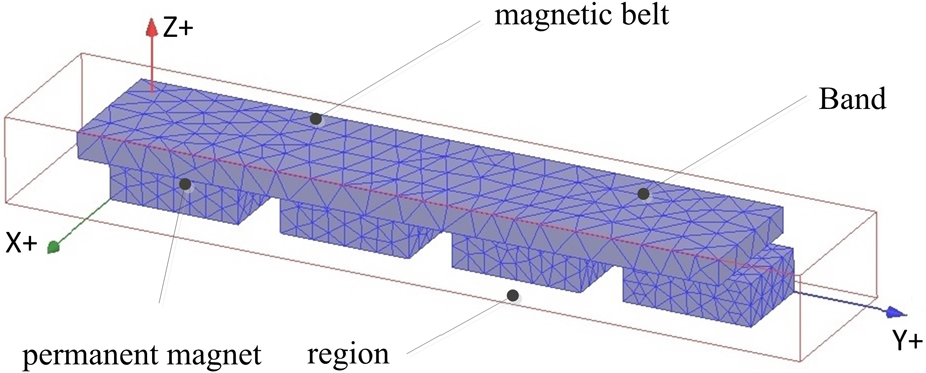
Diagram of permanent magnet suspension system mesh generation.
Impact of different air gaps on detent force
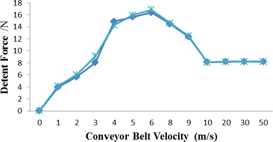
Under the circumstance that initial parameters remains unchanged, the size of the air gap between magnetic belt and a permanent magnet (0.001–0.003 m) is altered. In this case, curves of variations in the detent force of a magnetic belt along with velocity are as that given in Figure 4.

Change curves of detent force along with conveyor belt velocity when air gap varies.
As velocity of the magnetic belt rises, detent force goes up first and then decreases and tends to be stable finally. While parameters of the permanent magnet material remain the same, the detent force decreases as air gap increases from 1 to 3 mm. The detent force, whose maximum value is 16.3976 N, drops to 12.9023 N and 9.2584 N gradually, while the stable value reduces from 7.6 to 7.0 and 5.7 N.
Impact of permanent magnet material on detent force
Size of the air gap remains at 1 mm and material of the magnetic belt keeps unchanged, while other parameters of the permanent magnet are altered accordingly as follows: N27,
Change curves of detent force along with belt velocity when remanence varies.

Change curves of detent force along with belt velocity when coercivity varies.
As shown in Figure 5, coercivity for both permanent magnet materials is the same, but their remanence was different from each other. As the velocity of magnetic belt changes, detent force almost remains unchanged so that the above two curves nearly coincide with each other. According to Figure 6, such two kinds of permanent magnet materials have diverse coercivity that varies from
Impact of clearance between permanent magnet on detent force
If parameters of the permanent magnet system remain the same and clearances between permanent magnets are altered to be 0.01, 0.008, and 0.004 m, respectively, change curves of the magnetic belt’s detent force along with velocity are as presented in Figure 7.
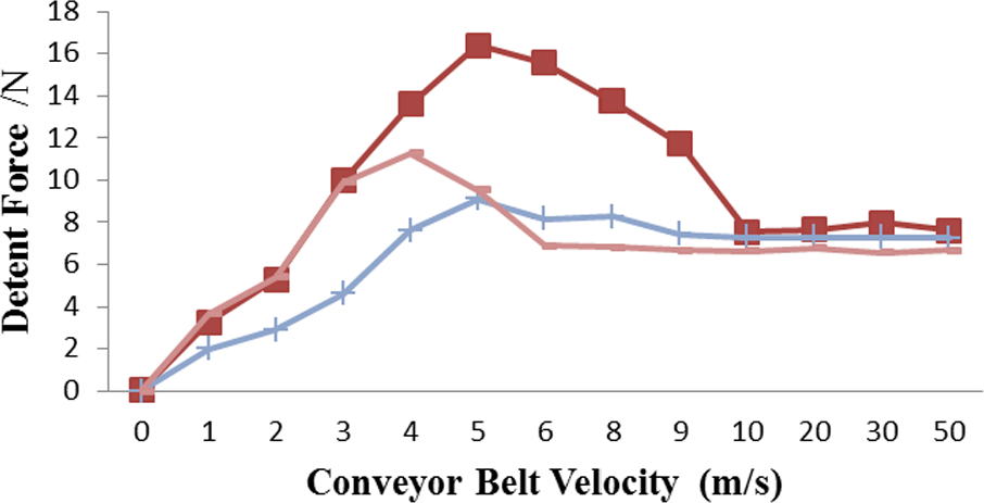
Change curves of detent force along with belt velocity when the clearance between permanent magnets varies.
With a decrease in the clearance between permanent magnets, detent force tends to go down on the whole and the maximum value of suspension force lowers from 16.3976 to 11.2887 and 9.1065 N, while the stable value declines from 7.6 to 7.3 and 6.7 N. If the detent force is stable, the minimum velocity of magnetic belt reduces from 10 m/s to around 6 m/s.
Simulation result analysis
Based on the analysis on the above simulation data, conclusions can be drawn as follows:
As shown in table 1, it is clear that the specific value between the maximum detent force and the maximum suspension force arrives at about 14%; therefore, it is necessary to study the detent force in a permanent magnet system.
Simulation results indicate that variation trend of detent force is consistent although parameters of the permanent magnet system are variable. As the belt velocity rises, it goes up and then declines and finally tends to be stable, which is in conformity with the theoretical result.
In the case that parameters of the permanent magnet remain unchanged, the larger the air gap is, the smaller the detent force will be as a whole.
Changes in
As the clearance between permanent magnets reduces, the detent force goes down overall and the minimum belt velocity also declines when it becomes stable.
Forces of the magnetic belt in different permanent magnet system parameters.

The influence rule of air gap, permanent magnet material, and their clearance on the detent force is discussed above as belt velocity changes. However, it is less likely for detent force to fully describe working performance of a maglev system. Considering that the specific value between suspension force and detent force is a critical parameter based on which the design power of a permanent magnet suspension belt conveyor can be calculated, it turns into an object of optimization. When the maximum value of buoyancy–resistance ratio is adopted, that is, on the premise of certain system parameters and magnet utilization factor, power required by the permanent magnet suspension belt conveyor to fulfill a certain conveying capacity is at its minimum level. In this article, velocity optimization of the buoyancy–resistance ratio is investigated with relation to certain parameters of the permanent magnet suspension system. The workflow is shown in Figure 8.
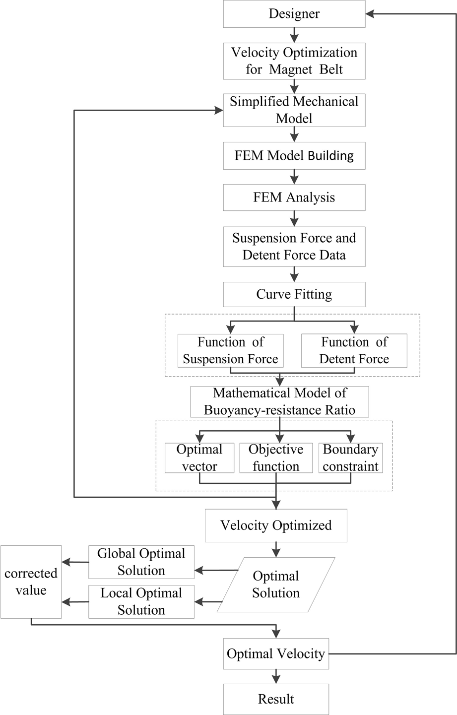
Flow chart of magnetic belt velocity optimization.
Computing instance
Parameters adopted by the permanent magnet suspension system are given below: length × width × height of permanent magnets could be expressed in 0.03 m × 0.02 m × 0.01 m, and they are uniformly distributed with a clearance of 0.01 m. NdFeB hard magnetic material N35 is selected for these permanent magnets. With respect to the magnetic belt, its length × width × height is 0.11 m × 0.02 m × 0.005 m, and the material utilized by it is Rare-Earth NdFeB. Furthermore, the air gap between a permanent magnet and the magnetic belt is 0.001 m. Finally, basic data of fitting consist of the detent force and the suspension force when velocity of the magnetic belt ranges from 0 to 14 m/s.
Mathematical model of buoyancy–resistance ratio
During suspension force fitting, curve type in the corresponding curve fitting tool is selected to be “power.” The function expression of suspension force curves is denoted as f(x) = a*xb + c. 18 Moreover, the relevant fitting effect and coefficients are presented in Figure 9 and Table 2, respectively.

Suspension force curve fitting.
Table of suspension force fitting result.

As shown in Table 3, error sum of squares (SSE) is 6.664, and the coefficient of determination (R-square) is 0.9992, which is close to 1. After calibration, the adjusted R-square is 0.9991 and the root-mean-square-error (RMSE) is 0.7783. In combination with Figure 9, it can be concluded that a better-fitting effect has the capability to describe changed rules of magnetic belt suspension force along with velocity in a more accurate manner.
Parameter list of suspension force fitting degree.
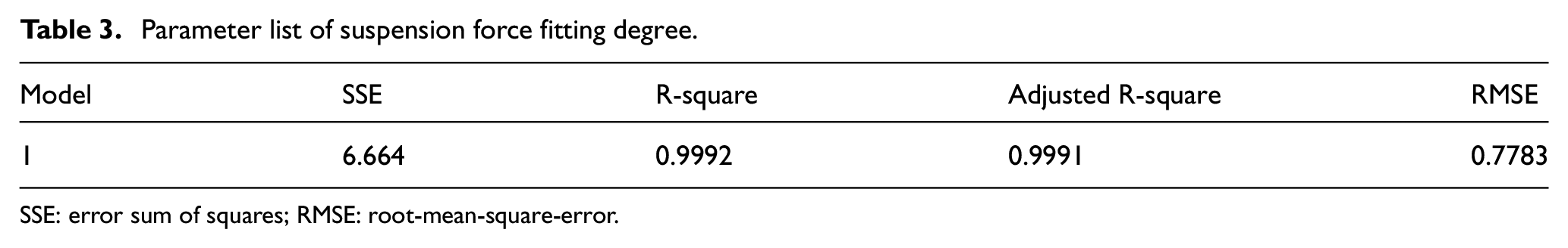
SSE: error sum of squares; RMSE: root-mean-square-error.
In the process of detent force fitting, curve type in the corresponding curve fitting tool was selected to be “polynomial.” The function expression of detent force curves was denoted as f(x) = p1*x6 + p2*x5 + p3*x4 + p4*x3 + p5*x2 + p6*x + p7. Moreover, the relevant fitting effect and coefficients were respectively presented in Figure 10 and Table 4.
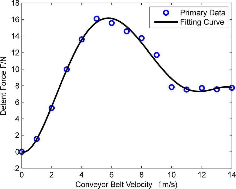
Detent force curve fitting.
Table of detent force fitting result.

As shown in Table 5, SSE is 3.253, and the coefficient of determination (R-square) is 0.9857, which is approximate to 1 as well. After calibration, the adjusted R-square is 0.9735, and the RMSE is 0.6817. In combination with Figure 10, it can be known that a better-fitting effect has the capability to describe change rules of magnetic belt detent force along with velocity in a more accurate manner.
Parameter list of detent force fitting degree.

SSE: error sum of squares; RMSE: root-mean-square-error.
Mathematical description of optimization problems
Optimal vector
Major factors that have an impact on detent and suspension forces of a maglev system include the air gap, the permanent magnet material, and the clearance between permanent magnets, etc. In this article, air gap of such a system is assumed to be 1 mm and the clearance to be 10 mm; besides, material selected for the permanent magnet is NdFeB N35 and that for the magnetic belt is Rare-Earth NdFeB. It is also assumed that
Objective function
In order to give full play to working performance of a maglev system, the maximum specific value between suspension and detent forces is employed as an objective function of optimization design to bring down the cost of such a system.
19
In other words, the objective function is the maximal value of
Boundary constraint
Considering that the permanent magnet suspension belt conveyor moves uniformly at a low speed and the maximum belt velocity of belt conveyors applied at present reaches about
To sum up, the mathematical model for optimization design of the permanent magnet suspension system is expressed as

Optimal calculation
As shown above, the mathematical model of buoyancy–resistance ratio of the permanent magnet suspension system is established, in which the velocity of the magnetic belt is an optimized variable. In MATLAB program, the change curve of buoyancy–resistance ratio is drawn and the variable v is set as: v = linspace(1,14,1000). As shown in Figure 11, when the buoyancy–resistance ratio reaches the maximum, the optimal value of conveyor belt velocity becomes 1.521 m/s; when the conveyor belt velocity reaches the optimal value, the buoyancy–resistance ratio becomes 15.8. According to Table 6, by referring to the standard running speed of the belt conveyor, the correction to its optimal value is 1.6 m/s
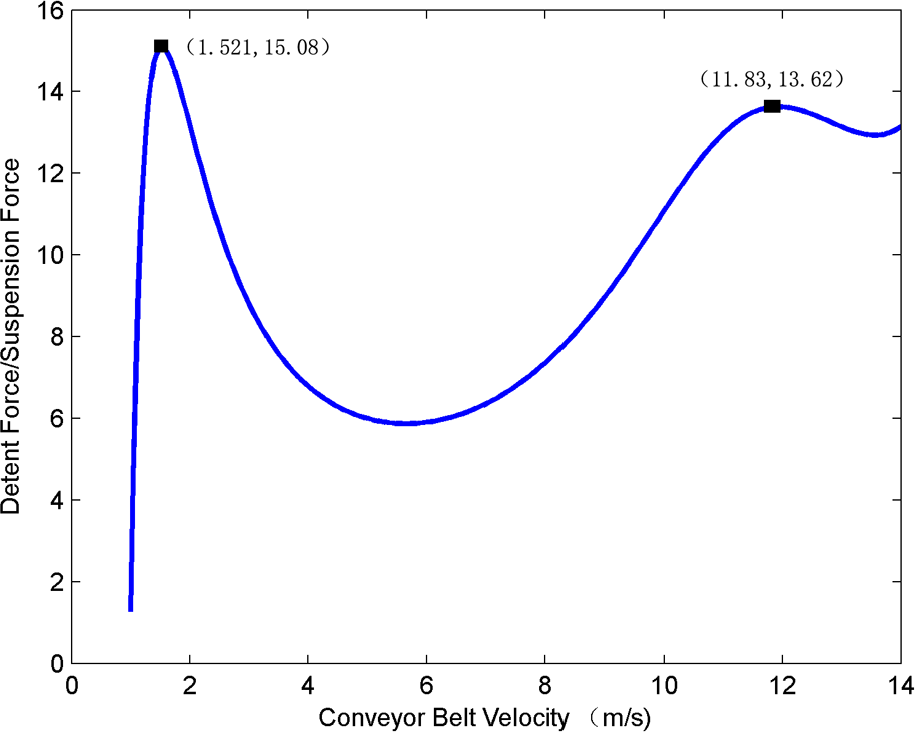
Change curve of buoyancy–resistance ratio with velocity.
Optimization results.

From Figure 11, we know that when the velocity is between 11–12 m/s, there is a local optimal solution. The development of belt conveyor technology, especially the low-resistance permanent magnet suspension belt conveyor, has made high-speed running possible. In MATLAB program, if the velocity variable is set as v = linspace(10,14,1000), the local optimal solution is v = 11.83 m/s. If the local optimal solution is put into the mathematical model, the buoyancy–resistance ratio is 13.62, which shows that it is necessary to do research into it.
FEM simulation
In this study, a local optimal solution denoted as
Suspension and detent forces of the magnetic belt are simulated in Ansoft. In addition to the selection of solver “Transient,” lengths of the permanent magnet, magnetic belt, and region adopted for mesh generation of the “Maximum Length of Elements” are 3, 10, and 15 mm, respectively. As a result, the total number of meshes obtained is 161,172. Regarding the “Solve Setup,”“Time Step” is set as 0.005 s, “Stop Time” as 0.04 s, and “Nonlinear Residual” as 0.002. “Global: Y” is selected during the “Motion Setup” and “positive” selected for “Translate.” The corresponding data value is 473.2 mm. As for “Mechanical,”
Figure 12 is the distribution diagram of a permanent magnet suspension system cloud map when the magnetic belt runs at 0.02 s. Figure 13 is the diagram of curves of suspension and detent forces to which the magnetic belt is subjected; Figure 14 is the diagram of velocity curves of the magnetic belt in the case of velocity =

Distribution diagram of permanent magnet suspension system cloud map.

Curve chart of forces on magnetic belt.

Velocity change curves of magnetic belt.

Displacement change curves of magnetic belt.
Comparison table of theoretical and computing values.

Conclusion
Based on the permanent magnet suspension system structure put forward by our research group and using the finite analysis method, this article analyzes the influence of factors such as air gaps, permanent magnetic materials, and clearance between permanent magnets on detent force with the changing velocity. The research results show that it is necessary to study the detent force of the permanent magnet suspension system.
When the velocity of magnetic belt reaches about 10 m/s, the magnetic resistance tends to be consistent, which provides a theoretical basis for the high-speed operation of the permanent magnet suspension belt conveyor.
In the permanent magnet suspension system, narrowing the clearance between permanent magnets can increase the suspension force and reduce the magnetic resistance, which is an effective way to improve the buoyancy–resistance ratio of the permanent magnet suspension system.
The buoyancy–resistance ratio is proposed as the optimization target in order to fully describe the working performance. A new method to determine the optimal buoyancy–resistance ratio is put forward. Through establishing the mathematical expressions, an optimized mathematical model for buoyancy–resistance ratio that takes velocity into account is set up, and the model shows that the global optimal solution of the optimal velocity of the magnetic belt is 1.6 m/s, and the local optimal solution is 11.83 m/s. The error we get by comparing the theoretical and computing values of the buoyancy–resistance ratio at the optimal velocity is 2.57%, which indicates the feasibility of the research method. This research provides a reference for the selection of operation parameters of the permanent magnet suspension belt conveyor.
Footnotes
Handling Editor: Jan Torgersen
Declaration of conflicting interests
The author(s) declared no potential conflicts of interest with respect to the research, authorship, and/or publication of this article.
Funding
The author(s) disclosed receipt of the following financial support for the research, authorship, and/or publication of this article: This research work was supported by the National Natural Science Fund Project (grant no. 51641501), the First-Class General Financial Grant from the China Postdoctoral Science Foundation (grant no. 2013M540506) and Doctoral Fund of Ministry of Education of China (grant no. 20133415110003).