
Abstract
Combined cycle power plants are gaining more attention throughout the world and their usage is increasing. This is because their efficiency is higher than simple Rankine or Brayton cycles. However, their efficiency could still increase. In this article, the driving force plot and exergy analysis are used to study the behavior of heat exchangers of a heat recovery steam generator in base case and off-design conditions. Based on the obtained results, a new method is proposed to improve performance of a heat recovery steam generator during the summers in which higher ambient temperature results in lower efficiency of plant. In this new method, hot flue gas at the heat recovery steam generator inlet is split which results in higher steam production in heat recovery steam generator. The results showed that the new proposed method is very beneficial and increases net output power of the plant. When split ratio increases from 2.5% to 15%, the power produced in steam turbine increases from 0.15 to 0.9 MW. It also increases exergy destruction of the heat recovery steam generator. This is due to higher mass flow rate of the produced steam and higher temperature difference between hot and cold streams. It is shown that this new method can reduce the negative effects of consuming more fuel in duct burner during the summers.
Introduction
Electricity is an important form of energy which plays a key role in sustainable development. Its usage has increased considerably during the last century due to population growth and technology improvement. A huge amount of electricity is generated in conventional power plants throughout the world where fossil fuels, such as coal, oil and natural gas, are burned and their chemical energy is converted into electricity. This brings about many environmental problems such as global warming, acid rains, and ozone layer depletion. To reduce these effects, many researchers tried to somehow improve power plants performance and consequently decrease their fuel consumption.
Combined cycle power plants have gained researcher’s attention due to their better performance and higher efficiency compared with other types of fossil fuel power plants. One of the methods to boost the performance of a combined cycle power plant is to increase the gas turbine inlet temperature. Bassily 1 tried to improve the performance of a combined cycle power plant by replacing gas turbine with a recuperated gas-reheat unit. The irreversibility of the heat recovery steam generator (HRSG) is reduced simultaneously. It was concluded that the proposed method could lead to both thermodynamic and economic advantages. In another study, 2 a new technique of gas turbine blade cooling (steam-cooled technique) which enables HRSG to be coupled with gas turbines with higher turbine inlet temperature was studied. Srinivas et al. 3 applied first and second laws of thermodynamics on steam-injected gas turbines and evaluated its effects on the performance of the combined cycle power plants. They concluded that although this concept reduces power generated in steam turbine, it increases gas turbine produced power and in general, it augments net output power of the system.
HRSG is an important part in combined cycle power plants which connects the Brayton and Rankine cycles together by recovering heat from gas turbine exhaust stream. Many have tried to boost its performance so that the plant’s efficiency increases. Feng et al. 4 proposed a general model to analyze different types of HRSG through energy analysis. They showed that the selection of heat exchangers layout can change the system performance considerably and therefore performing an optimization process to achieve the maximum efficiency is unavoidable. Franco and Casarosa 5 considered different methods to improve performance of the combined cycle power plant. They showed that utilizing HRSG optimization, gas turbine reheat, and gas-to-gas recuperation, total efficiency of the plant increases considerably. In another study, Franco and Russo 6 tried to optimize the performance of HRSGs by selecting optimum value of pinch temperature by considering thermodynamic and economic objective functions. They showed that using this method, overall efficiency of the plant could reach nearly 60%. Manassaldi et al. 7 used mixed-integer non-linear programming in order to boost the efficiency of an HRSG and considered energy efficiency as their objective function. They solved their mathematical model in GAMS.
MT Mansouri et al. 8 compared exergy efficiency and capital cost of three types of HRSG including a dual pressure, a triple pressure with reheat, and a triple pressure without reheat. They concluded that increasing pressure levels in HRSG increases both exergy efficiency and investment cost. However, in general, it is feasible to increase pressure levels. Other researchers9–11 reached the same conclusion using different methods. For example, Woudstra et al. 11 used internal exergy efficiency, value diagram and exergy flow diagram concepts, while Mohagheghi and Shayegan 9 developed a non-linear equation in general form and then solved it utilizing the hybrid Newton methods.
As discussed above, many researchers have used exergy analysis as a tool to find improvement possibilities in power plants. In addition to exergy analysis, some have used pinch analysis in order to improve the performance of energy systems. It is especially helpful in optimizing heat exchanger networks (HENs) and integrating energy systems. Yoon et al. 12 analyzed the HEN of an industrial ethyl benzene plant to improve the performance of the system. They proposed a new HEN which has the capability of reducing total energy cost by 5.6%. Fernández-Polanco and Tatsumi 13 used pinch analysis to optimize integration of anaerobic digestion and wastewater treatment plant. Pinch analysis could also be combined with exergy analysis to give a better insight about the situation and improvement possibilities. This combined analysis has been applied to many different energy systems. Quijera et al. 14 used this analysis to integrate solar energy and heat pump technologies. Using the aforementioned systems, they recovered the internal heat which was previously released into the ambient. In another study, 15 both pinch and exergy analyses were used to couple the diary process with solar thermal energy in order to provide the required hot water. They used pinch analysis in the optimization process to find the energy targets. Ghorbani et al. 16 applied pinch and exergy analyses to a refrigeration cycle in natural gas liquid recovery plant. First they optimized the plant which reduced power consumption of the compressor by 170 kW and then they used another refrigerant which lowered the power consumption of the compressor. Arriola-Medellín et al. 17 used combined pinch and exergy analyses to analyze the performance of a steam power plant. They showed that the current design of the system leads to some energy losses. By changing the system’s design, they increased the total efficiency of the plant by 0.81%.
As mentioned above, HRSG is one of the most important components in combined cycle power plants, and improving its performance can generally boost the efficiency of the plant. In this article, a new method is proposed to improve the performance of the HRSG and increase the power generation of the power plant. This method is based on the split concept, and it has been used before in improving the HRSG’s performance. Zebian and Mitsos 18 used the split concept in an HRSG with flue gas recycling to reduce the heat exchange area and the power required for recycling, simultaneously. To do so, they split the hot flue gas and diluted it with recycled gas to achieve tolerable temperature at the HRSG inlet. They performed a multi-objective optimization on the system. The results showed that using this method, the required power and area could be reduced by 18% and 12%, simultaneously. Here, the same concept is used, but with a notable difference. In this article, the splitting occurs at the HRSG inlet, not at its outlet. This is the first time that the splitting process is performed at the beginning of the HRSG. The idea behind this method is to produce higher amount of steam in the evaporator. This method results in thermal stresses reduction in superheaters as they are the first set of heat exchangers which recover heat from the flue gases. Therefore their lifetime increases. It also makes the control strategy in desuperheater section easier. This method improves the performance of the plant, especially during the summer in which the ambient temperature is higher. In these situations, performance of the gas turbine deteriorates, which results in lower available energy in the gas turbine exhaust stream to recover. The proposed idea helps the system to recover energy as much as possible resulting in the compensation of power production. Both exergy and pinch analyses are applied on the system to study the effect of these changes on the plants performance, and the results of the new method are compared with base case condition.
System description
The analysis is performed on Damavand power plant, located in Tehran, Iran. Its capacity is equal to 2868 MW, which makes it the biggest power plant in the Middle East. It is comprised of 12 gas turbine units, each of which has a capacity of 159 MW and 6 Rankine cycles with a total capacity of 960 MW. Also, there are 12 HRSGs in the plant. Figure 1 shows the schematic diagram of the Damavand power plant. It is known that two gas turbines, two HRSGs and one steam turbine comprise a power block, but for simplicity, only one gas turbine and one HRSG are shown in the figure. Design conditions of the power plant are presented in Table 1.

Schematic diagram of Damavand power plant.
Design condition of the power plant.

HRSG: heat recovery steam generator; HP: high pressure; LP: low pressure.
The air is transferred into the combustion chamber after being compressed in the compressor. Then, the hot flue gas expands in the gas turbine and generates power. Since, the gas turbine outlet temperature is still high, its energy is recovered by the HRSG. In the HRSG, water is heated in the condensate preheater (CPH). The next component is deaerator (DA) which is responsible for removing oxygen and other dissolved gases from the water. The feedwater is pumped and divided into high-pressure (HP) and low-pressure (LP) streams after passing through the DA. The LP stream goes through an evaporator and a superheater, where it first evaporates into saturated steam and is then converts into superheated steam. Finally, it is delivered into the LP section of the steam turbine. However, HP stream passes through two economizers, an evaporator, and two superheaters. Also, between the two superheaters, there is a desuperheater which sprays water in the steam to lower its temperature. It should be mentioned that, in order to increase the energy content of the flue gas, a duct burner is placed at the inlet of the HRSG, which increases the flue gas temperature by burning a small amount of fuel. The produced steam goes to the HP section of steam turbine, where it expands and generates power. Steam turbine outlet stream is a saturated mixture of water and steam that should be condensed before going to the HRSG. The condenser performs this action and sends the feedwater to the HRSG.
Performance of the combined cycle power plant deteriorates during the summer. This is because ambient air temperature increases during the summer, which affects the performance of gas turbine and cooling tower. Increasing ambient air temperature decreases its density, therefore the mass flow rate of air and consequently the mass flow rate of the flue gas decreases. As a result, the amount of heat delivered to the HRSG is reduced. However, increasing the ambient temperature does not allow the cooling water to be completely cooled in the cooling tower. Consequently, feedwater enters the HRSG at a higher temperature, which results in lower heat recovery in the HRSG.
To resolve the problem, a new method is proposed in this article (Figure 2). In the new method, the flue gas stream is split and the new stream bypasses the two superheaters and is then combined again with the main stream. This method decreases the steam temperature at the superheater outlet slightly, but it increases the heat delivered to the HP evaporator, which results in higher mass flow rate of produced steam. In general, net output power of the system increases, which compensates the performance deterioration of gas turbine and cooling tower.

Schematic diagram of the new proposed method using split concept.
Exergy analysis
Exergy is an indicator which shows the quality of energy. It could be transferred via heat, work, and mass. Exergy of heat and work are calculated by equations 1 and 2 as follow:


In the above equations,

As can be seen, equation (3) has four subcategories, including kinetic, potential, physical, and chemical exergies. Usually, the first two terms are ignored, due to insignificance changes of speed and elevation of stream in power plant components. Therefore, to calculate the specific exergy of mass transfer, only physical and chemical exergies should be calculated. These two parameters are computed using equations (4) and (5)

where

In equation (6),
After calculating these parameters for each stream, exergy destruction and exergy efficiency of each component could be computed. Exergy destruction of each component is calculated by considering each component as a control volume and applying exergy balance to them as follows

However, exergy efficiency of the components does not have a unique formula and there are different definitions for it. In this article, we used fuel-product definition. 21 Table 2 shows the required equation to calculate exergy destruction and exergy efficiency of each component.
Exergy destruction and exergy efficiency of each component.

HRSG: heat recovery steam generator.
To perform exergy analysis, first, the system is simulated in Aspen software and then the results are used in MATLAB software to calculate the exergy destruction of each component in the system.
Pinch analysis
Pinch analysis is a methodology which was first proposed by Linnhoff 22 after the oil crisis in the 20th century. Its goal is to maximize energy recovery in industrial processes to reduce their need for external energy sources. In this method, all streams are categorized into either hot or cold streams. Hot streams are those which should be cooled by losing their heat and cold streams are those which should be heated. The aim of the pinch analysis is to provide the required energy of cold streams by the hot streams. During the years, different kinds of tools have been developed, which can help the researchers to improve their process. The first one is the composite curve. In this plot, all hot streams are combined together and form a single line which represents all the hot streams in the process. The same thing occurs for the cold streams. These two lines are drawn in the same plot where its vertical axis shows the temperature and the horizontal axis shows the enthalpy. The lowest vertical distance between the two lines is called the pinch point. Figure 3 shows a sample of a composite curve for a process. The pinch point, divides the process into two regions, namely, above the pinch and below the pinch. Based on this, three golden rules are defined as follows:
No heat should be transferred across the pinch point;
Cold utility should not be used above the pinch;
Hot utility should not be used below the pinch.

Composite curve for a sample process.
Although a composite curve could calculate the overall energy target, it cannot determine the amount of energy that should be delivered to the process at different temperatures. To solve this issue, a grand composite curve is used. Figure 4 shows a sample of this plot. As can be seen, the total energy demand calculated by the composite curve could be delivered at different levels, while the grand composite curve specifies the amount of each of them.

Grand composite curve for a sample process.
One of the most important goals of pinch analysis is to minimize the total annual cost of the plant without negatively affecting on the thermodynamic performance of the system. To do so, the total area of heat exchangers should be minimized. There are different tools to achieve this goal. One of them is the driving force plot (DFP), which was introduced by Linnhoff and Vredeveld. 23 As known, the required area for a heat exchanger is at its minimum value when it has a vertical heat transfer. DFP helps to identify these heat exchangers. It is drawn by plotting the hot temperature versus cold temperature of the heat exchanger. A schematic of this diagram is shown in Figure 5.

Driving force plot.
Individual matches can be shown in the DFP. In an ideal match between streams, the heat exchanger will coincide with the DFP. If a heat exchanger deviates from the DFP, it indicates that the match is not ideal and it has a criss-cross heat transfer. Therefore, it should be modified. 24 Generally, it could be said that the DFP is a beneficial tool for analyzing heat exchangers, individually.
Validation
To perform the analysis, the plant is simulated in Aspen energy analyzer 25 and the results are compared with the actual data provided by the manufacturer’s data sheet. Figure 6 shows the HEN used in the simulation.

Heat exchanger network of the HRSG used in simulation.
The required area for each component in the HRSG is computed by the software and then it is compared with the actual data provided by the plant. The comparison is shown in Table 3. As can be seen, the difference between the actual data and the computed data are within reasonable range.
Comparison between actual data and calculated area.

HP: high pressure; LP: low pressure; DA: deaerator; CPH: condensate preheater.
Also, based on the data provided by the manufacturer, when minimum temperature difference of the plant is equal to 15°C, total heat transfer area of HRSG is at its minimum. To study this, the total cost of the HRSG versus the minimum temperature difference is drawn in Figure 7. As shown in this figure, the total cost of the HRSG is at its minimum when the minimum temperature difference is equal to 16°C. This is in good agreement with the plant’s data.

Variation of total cost of HRSG with minimum temperature difference.
Based on the presented data, it could be concluded that the simulation is valid and the results are satisfactory.
Results and discussion
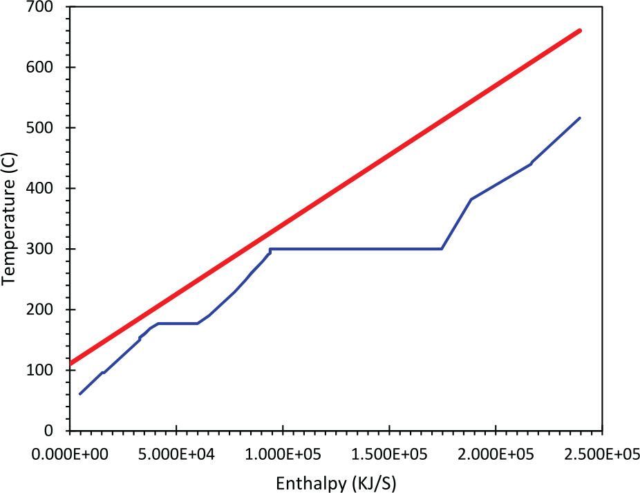
In this section, the results of simulation are presented. Three different scenarios are defined and each one of them is simulated in the software. The first scenario is the base case condition. In this scenario, flue gas and water enter the HRSG at 620°C and 49°C and steam is produced at 523°C and 234°C, respectively. Also, mass flow rate of HP and LP steam are equal to 66.51 and 8.84 kg/s. Composite curve and DFP for this scenario are shown in Figures 8 and 9, respectively. As can be seen in Figure 8, minimum temperature difference between hot and cold streams occurs at HP evaporator. Also, Figure 9 shows that all heat exchangers are placed well (or placed in appropriate positions) and they are consistent with the DFP, which indicates that they are close to vertical heat transfer, except for the LP superheater. However, since its heat load is negligible in comparison with other components in the HRSG, it does not have a significant impact on the total performance of the HRSG.

Composite curve for HRSG in base case condition.

Driving force plot of the HRSG in base case condition.
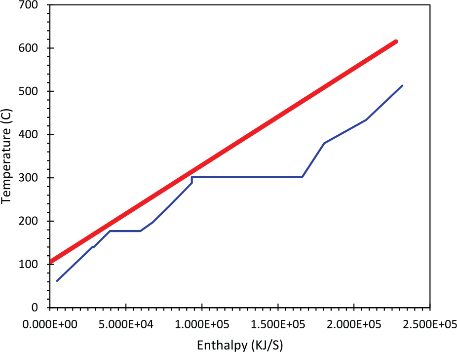
The second scenario is similar to the first scenario. The only difference between these two is that the second scenario occurs during the summer. As mentioned before, during the summer, due to increase in the ambient temperature, performance of gas turbine and cooling tower deteriorates. This causes the mass flow rate of flue gas to reduce, which lowers the energy delivered to the HRSG. However, due to poor performance of cooling tower, feedwater enters the HRSG at higher temperatures in comparison with the first scenario, in a way that it increases from 49°C to 62°C. All these parameters change the performance of each component in the HRSG. Due to these changes, the total mass flow rate of the produced steam in this scenario decreases. The results of the second scenario are shown in Figures 10 and 11.
Composite curve for HRSG during summer.

Driving force plot of the HRSG during summer.
As can be seen in Figure 11, three heat exchangers are far from the DFP plot, which indicates that their performance should be modified. Two of them are HP superheaters and the third one is an LP superheater. As mentioned before, heat load of LP superheater is far lower than total heat load of HP superheaters (1.1 vs 240 MW). Therefore, LP superheater is neglected in this study, and the main focus is on HP superheaters.
There are three ways to modify the performance of the HP superheaters. The first one is to change their inlet and outlet temperature. The second one is to change the mass flow rate (CP) of hot and cold streams by either splitting or changing streams, and the third one is to carry out both of these methods simultaneously. The first method can be done by burning more fuel at the HRSG inlet to increase flue gas temperature. However, this process results in higher fuel consumption, and as a result, efficiency of the plant will decrease. In addition, it has a negative effect on the environment. The second method can be done by splitting hot stream and bypassing some heat exchangers. In this article, we performed both of these methods simultaneously. The splitting concept is performed as demonstrated in Figure 2. The flue gas stream is divided into two streams. The first stream passes thorough HP superheaters and the second stream bypasses these two exchangers and is combined with the main stream at the HP evaporator inlet. It should be noted that the mass flow rate of the second stream is equal to 15% of the main flue gas. This is the third scenario which is simulated and the results are presented in Figures 12–14. Figure 12 illustrates the HEN of this scenario. The splitting concept is shown in this figure completely. Also, the composite curve and DFP of this scenario are shown in Figures 13 and 14, respectively.

Heat exchanger network design after splitting.
Composite curve of HRSG after splitting.

Driving force plot after splitting.
As can be seen in Figure 14, after splitting, the two HP superheaters coincide with the DFP plot which indicates that the heat exchangers are in their ideal heat transfer condition. In fact, this new configuration decreases heat transfer in HP superheaters and allows more heat transfer in the HP evaporator. Therefore, more steam can be produced in the HP section. However, when mass flow rate of steam in HP superheaters increases and mass flow rate of flue gas decreases simultaneously, temperature of HP steam might slightly decrease. This issue can be tackled by burning some fuel at duct burner, which increases the HP steam temperature to the desired value. In fact, this is another advantage of the new proposed configuration. It is acknowledged that outlet temperature of duct burner is directly dependent on the maximum bearable temperature by the material of HP superheater. The thermal strength induced in the superheater should not exceed the allowable value. When the flue gas is split, lower amount of heat is delivered to HP superheaters and since their temperature is lower than normal temperature, it allows us to burn more fuel in the duct burner. This increases the efficiency of the HRSG by reducing the flue gas temperature at the end of the HRSG. This process is illustrated in Figure 15. In another words, the higher the inlet temperature of the flue gas, the lower the temperature of the flue gas at the HRSG outlet, which results in higher HRSG efficiency. This could not be done in the first and the second scenarios due to thermal stresses in HP superheaters.

Effect of higher duct burner outlet temperature in the HRSG performance.
It is also worth mentioning that all these variations affect the performance of the LP section of the HRSG. However, since both temperature and mass flow rate of LP section are lower than that of the HP section, it does not have a significant effect on the total performance of HRSG. This is shown in Figure 16. The figure is extracted from the power plant’s document. As can be seen in this figure, the effect of variation of HP steam temperature is higher than the LP steam temperature. Therefore, the inconsiderable changes in the LP steam temperature can be neglected.

Effect of HP and LP steam temperature on the generated power by steam turbine.
The results showed that during the summer, the total steam produced in HRSG reduces by 8.46% compared with the base case condition in which the power generated in the steam turbine decreases considerably. However, using the new proposed configuration, the reduction in the produced steam reaches up to 1.96% merely compared to the base case condition. Therefore, more power can be generated in the steam turbine in the third scenario in comparison with the second scenario which alleviates the effect of higher ambient temperature on the net generated power of the plant.
An exergy analysis is also performed to calculate exergy destruction and exergy efficiency of each component in the HRSG. Figure 17 shows the value of exergy destruction in each component. As can be seen, the highest amount of exergy destruction occurs in HP superheaters, HP evaporator, and CPH. In both HP superheaters, the amount of exergy destruction in the third scenario is much higher than the first and the second scenarios. This is due to the higher temperature difference between hot and cold streams in this scenario. This is due to the fact that, as mentioned before, more fuel can be burned in the duct burner, which increases the exergy destruction in these two components. It should be mentioned that the little difference between exergy destruction in the first and the second scenarios are due to higher mass flow rate of the produced steam in the first scenario, which results in higher exergy destruction in respect to the second scenario. The difference between exergy destruction of the three scenarios in HP evaporator is lower than the HP superheaters. Nonetheless, the highest amount of exergy destruction still belongs to the third scenario which is due to higher amount of produced HP steam and higher temperature difference. The amount of exergy destruction in other components is approximately equal in all the scenarios.

Exergy destruction in each component of the HRSG in all scenarios.
Also, exergy efficiency of each component in the HRSG and the total HRSG efficiency are shown in Table 4. As can be seen, the difference between the first and the second scenarios are negligible. This is because mass flow rate of both steam and flue gas are reduced simultaneously. Also, since feedwater in scenario 2 enters the HRSG at higher temperature, it reduces the total HRSG efficiency, in a way that it reduces from 81.6% in scenario 1 to 81.26% in scenario 2. In the third scenario, exergy efficiency of HP section changes considerably. As can be seen, the stream splitting reduces the exergy efficiency of HP superheaters and HP evaporator. However, since in this condition, more steam is produced, the total exergy efficiency of the HRSG increases and reaches 81.77%.
Exergy efficiency of each component and total HRSG.

HRSG: heat recovery steam generator; HP: high pressure; LP: low pressure; DA: deaerator; CPH: condensate preheater.
As mentioned before, mass flow rate of bypass stream was considered to be 15% of the total mass flow rate of turbines exhaust stream. The value of 15% was chosen because the main stream should have enough energy so that the superheaters could convert saturated water produced in the boiler into superheated condition. If split ratio increases further (higher than 15%), the main stream could not convert water into superheated steam. This would affect the turbine blades and may cause serious problems.
A sensitivity analysis is performed to study the effect of split ratio on the power generated by the steam turbine. The result is presented in Figure 18. As it is shown, increasing the split ratio increases the power generated by steam turbine. This is due to the increase in mass flow rate of HP stream in HP evaporator in a way that when split ratio increases from 2.5% to 15%, augmentation in generated power of steam turbines from changes from 0.15 to 0.9 MW. Also, by increasing the split ratio, the graph reaches an optimum value in which augmentation in the generated power reaches its maximum value.
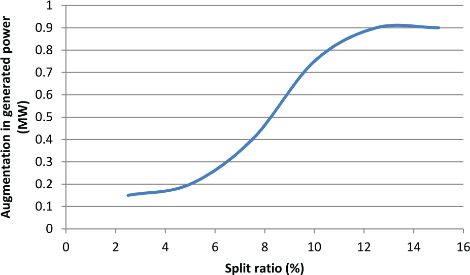
The effect of split ratio on generated power by steam turbine.
Conclusion
In this study, a new method is proposed to improve the performance of an HRSG during the summers in which ambient temperature increases. This temperature increment results in deterioration in performance of the gas turbine and cooling tower, which lead to poor performance of the HRSG. To solve this issue, a fraction of the flue gas was extracted, which bypasses the HP superheaters, and its energy was delivered to the HP evaporator to increase the mass flow rate of the produced steam. The results showed that by utilizing this new method, HP superheaters are closer to their ideal heat transfer condition (vertical heat transfer). Also, this new method allows us to produce more power in steam turbines, which results in higher plant efficiency. However, exergy analysis revealed that exergy destruction of the HRSG increases, which is due to higher temperature difference between hot and cold streams. However, it could be concluded that this new method is generally a beneficial way to increase the net power generated in combined cycle power plants.
Footnotes
Appendix 1
Acknowledgements
The authors thank Dr Mohammad Hossein Ahmadi for his helpful advice on various technical issues.
Handling Editor: Moran Wang
Declaration of conflicting interests
The author(s) declared no potential conflicts of interest with respect to the research, authorship, and/or publication of this article.
Funding
The author(s) received no financial support for the research, authorship, and/or publication of this article.