
Abstract
The invariant points of the quarter vehicle model shape many properties concerned in vehicle suspension design. Although they have been studied for years, the invariant points are still confusing for their different traits. Hence, the existing invariant points are sorted and analysed. Meanwhile, the invariant points of the semi-active suspension were introduced. In this article, a further study on the invariant points of the semi-active suspension is conducted, which provides insight for suspension optimization. In detail, an equivalent linear approximation model, derived from the transformation of the semi-active suspension model, is utilized to analyse the invariant points of the semi-active suspension. With the equivalent linear approximation model, the invariant points of the sky-hook semi-active suspension are proved to be highly dependent on the adjustable damping range. In fact, the frequencies and magnitudes of the invariant points, as the limit of the semi-active suspension, are determined by the adjustable damping range. Consequently, the influence rule of the adjustable damping range on semi-active suspension performance is revealed, which provides insight for the optimization of the damping for different demands. Experimental study shows that the invariant points are real, not just exist in the theoretical analysis.
Introduction
Generally, two kinds of quarter vehicle models are utilized to deal with the suspension analysis and design, which are shown in Figure 1. The multi-body suspension model,1–4 as shown in Figure 1(a), could describe the suspension in more detail and express the nonlinear geometry and dynamics well. While the 2-degree-of-freedom (DOF) system,5–7 as shown in Figure 1(b), simplifies the suspension into the sprung mass ms and the unsprung mass mu which are connected by the linearized suspension spring ks and damper cs, the tyre is simplified by a linear spring kt. Damping of the tyre is often neglected in this model for the following reasons:
The tyre damping is actually very small. Most of the energy dissipation comes from suspension damping. So the neglect of tyre damping is justified except the extreme case in which the suspension damping is infinitely small.8,9
The road velocity input is usually regarded as the white noise, 10 with which the tyre damping would lead to infinite energy input.9,11,12 Hence, the neglect of tyre damping is also meaningful to vehicle modelling.

Quarter vehicle model: (a) multi-body model and (b) simplified model.
Moreover, the simplification of the suspension model also brings the following advantages to the suspension study. 9
Less parameters are needed to complete analysis, and valid results can be easily obtained;
High efficiency in controllable suspension study, such as semi-active and active suspensions;
Good generality for different suspension structures.
The invariant point is a typical phenomenon that suits for the simplified suspension model with neglecting tyre damping.9,13,14
Invariant points are some special points in the frequency responses of the vehicle body acceleration, tyre deflection, suspension deflection or other associated frequency responses. These special points have certain responses at specified excitation frequencies. In Zhuang et al., 15 the invariant points are sorted into three categories: fixed invariant points (FIPs), invariant points of the linear time-invariant model (LIPs) and invariant points of semi-active suspensions (SIPs). FIPs are a kind of invariant points that are independent of the suspension components, that is, the spring, damper and actuator. Once the simplified quarter vehicle model is used, this kind of invariant points always exist,14,15 regardless of passive, semi-active or active suspensions. KJ Hedrick 16 derived FIPs through three transfer properties of interest (the sprung mass acceleration, suspension deflection and tyre deflection) and made an investigation of suspension improvement limits. R Rajamani 17 studied the FIPs of a 2-DOF vibration system which has a displacement disturbance on the sprung mass. This study analysed the FIPs’ existence with two kinds of disturbance inputs applied to the machine, force and displacement. D Karnopp 9 considered the FIPs as the ‘fruit on an oversimplified tree’ which is much in line with the study of Levitt and Zorka. 8 This conclusion leaves suspension designers with the hope that better suspensions could be designed despite the strong limitations implied by the simple linear quarter car model.
LIPs are a kind of invariant points that are only suitable for the linear time-invariant suspension model,13,18 that is, the linear passive suspension model. SM Savaresi et al. 13 introduced the existence premise of LIPs. While keeping the tyre stiffness, sprung mass, unsprung mass and suspension stiffness constant, the LIPs appear by changing suspension damping.13,15 In passive suspensions, the LIPs provide insights into the effects of damping on vehicle performance. LIPs are critical points across which a certain damping has opposite effects on vehicle. 15 This characteristic of LIPs is helpful to develop semi-active control algorithms.19,20
The invariant points in the semi-active suspension which have similar properties to LIPs are named SIPs. It is of great potential in the semiactive suspension study. For example, the SIPs as a limitation of the semi-active suspension could provide insight for the suspension optimization. To date, little research involves the properties of SIPs. Therefore, this article attempts to explore the relationship between vehicle performance and SIPs. The main contributions are as follows:
The expressions of SIPs are derived with an equivalent linear approximation model (ELAM); meanwhile, the influence of the adjustable damping range on SIPs is unravelled through two theorems.
The effects of the adjustable damping range on vehicle performance are discussed, which provides insight for the damper design optimization.
The existence of invariant points including LIPs, FIPs and SIPs is validated through experiments.
This article is organized as follows: In section ‘Invariant points of the semi-active suspension’, the invariant points in the sky-hook semi-active suspension are introduced. Section ‘Derivation of SIPs’ proposes an ELAM to derive the invariant points. Section ‘Validation of ELAM’ validates the effectiveness of ELAM on SIPs’ derivation. In section ‘Influence of SIPs on vehicle performance’, two theorems related to the properties of the invariant points are proposed and proved; meanwhile, the effects of the adjustable damping range on the vehicle performance are discussed. Further experimental verification is provided in section ‘Experimental study’. Finally, this article is concluded in section ‘Conclusion’.
Invariant points of semi-active suspensions
Semi-active suspension modelling
The sky-hook semi-active suspension model shown in Figure 1(b) can be written as follows


where Λc = cmax + cmin and Δc = cmax – cmin, with cmax and cmin being the maximum and minimum damping of the semi-active controlled damper, respectively. Hence, Δc represents the adjustable damping range.
Invariant properties of semi-active suspensions
Transfer properties from the road velocity to sprung mass acceleration Ha(s), tyre deflection Htd(s) and suspension deflection Hsd(s) are usually related to ride comfort, road-holding and suspension limitation. Hence, the invariant points of the three concerned transfer properties have great effects on suspension design and tuning.
Figure 2 shows the two concerned transfer properties Ha(s) and Htd(s). Different dampers are adopted in the semi-active suspension. The values of adjustable damping range Δc of different dampers are the same. The Λc value of different dampers is an arithmetic progression. As shown in Figure 2, it is easy to find that the frequency response curves intersect at several points. The number of points is equal to that of LIPs and the positions are similar to LIPs. 15 They are the invariant points of the semi-active suspension, that is, SIPs.
SIPs of the concerned transfer properties: (a) sprung mass acceleration and (b) tyre deflection.
With different damping, the frequency responses of the sky-hook semi-active suspension present similar properties to those of the passive suspension. Large or small Λc is needed in different frequency ranges to improve the vehicle performance. But the influence of different Λc values on the magnitudes is not significant below fs – 1 and fs – 3, as shown in Figure 2(b). This feature is attributed to the good vibration isolation of the sky-hook suspension around the first-order resonance.
Derivation of SIPs
ELAM
Since semi-active control algorithms are nonlinear, the closed-loop system also behaves nonlinearly. 21 Therefore, it is hard to derive analytical expressions of the concerned transfer functions. So it is also difficult to derive the expressions of invariant points. To deduce the expressions of SIPs, the linear approximation of the sky-hook semi-active suspension is proposed in this study. As shown in Figure 3, the semi-active suspension is approximately equivalent to a passive suspension. The passive suspension has a constant damping of Λc/2. The stiffness is also constant, the value of which will be determined in the following.

Linear approximation of semi-active suspension.
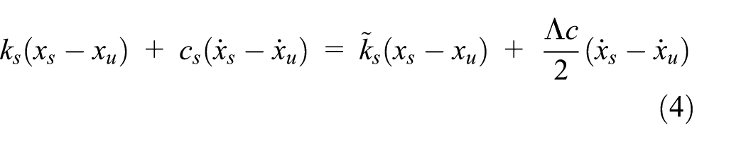
In the ELAM, it is assumed that the total suspension force generated by spring and damper remains the same as that of the semi-active suspension. So, the following equation can be obtained
Then the following equation can be derived by substituting equation (2) into equation (4)

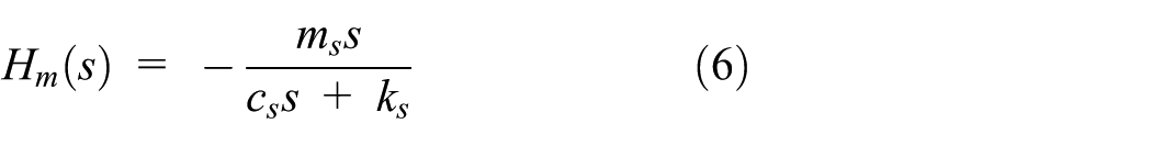
With equation (1), it is easy to get the transfer function from
Let us define the phase angle as Ψ(·). Hence, the phase angle between

where

where κ is an index with regard to the signs of
As shown in Figure 4, the direction index tends to 0% as the frequency ω increases, which means that the directions of

where

where

With the expression of
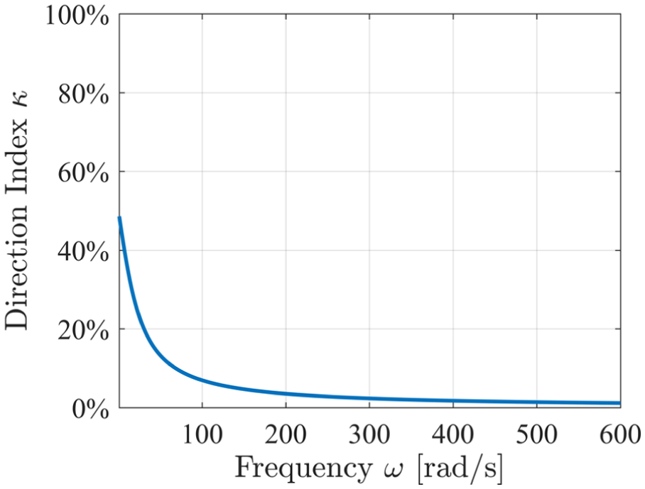
Direction index at different frequencies.
Frequencies of SIPs
With the ELAM, the frequencies of SIPs can be derived in the same way as those of LIPs, which is presented in Savaresi et al. 13 The frequency expressions of SIPs are listed in Table 1. From the expressions, it can be seen that the SIPs have very similar expressions to the LIPs. In fact, the LIPs represent an extreme case of SIPs when the adjustable damping range Δc is infinitely small.
Frequencies of the SIPs.

SIPs: invariant points of semi-active suspensions.
Here,
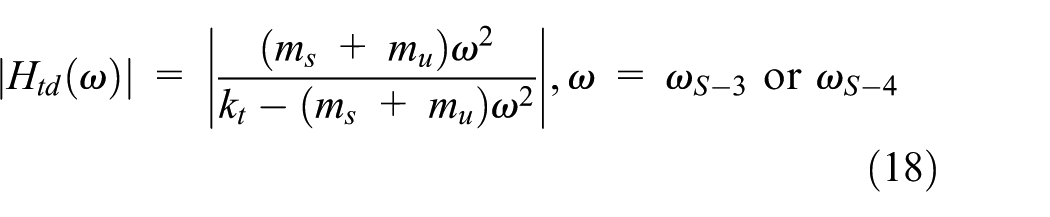
Magnitudes of SIPs
The magnitudes of the SIPs restrict the vehicle performance around the corresponding SIPs. The derivation of the magnitudes can also be conducted with the transfer functions of ELAM.
The motion equation of ELAM can be written as

Magnitude expressions of SIP-1 and SIP-2
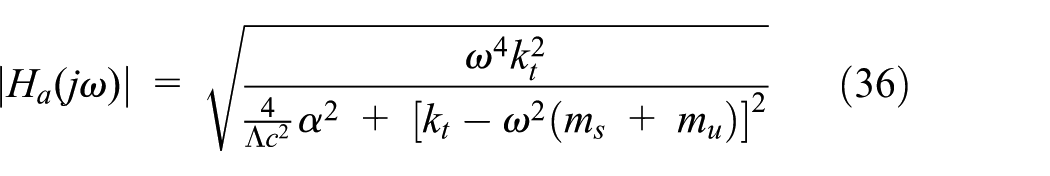
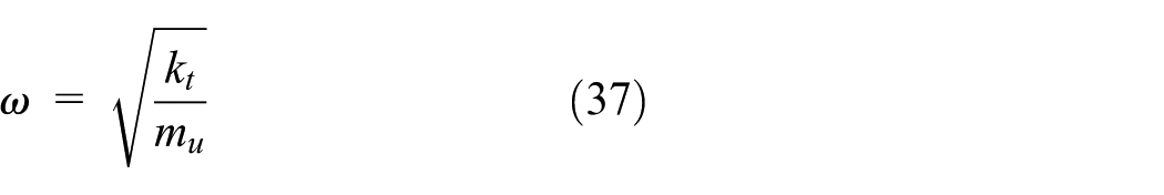
The transfer function from the road excitation to the sprung mass acceleration can be derived from system (12)

Then the transfer function Ha(s) can be rewritten by setting

For simplicity, let us define
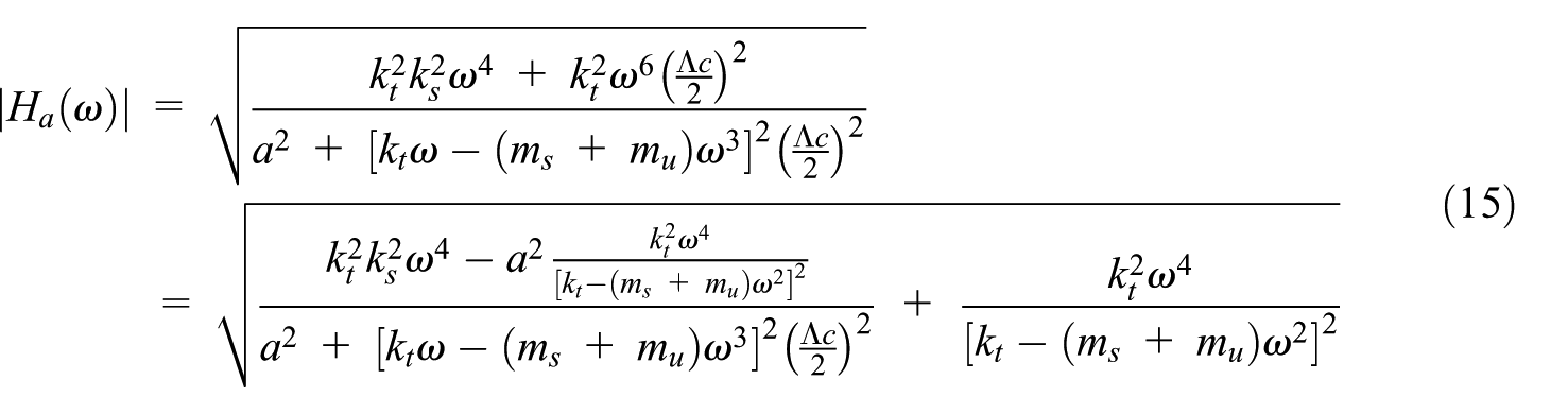
When

Consequently, the magnitude expressions of SIP-1 and SIP-2 can be derived from equation (15) as follows

Magnitude expressions of SIP-3 and SIP-4
The derivation of the magnitude expressions of SIP-3 and SIP-4 is similar to that of SIP-1 and SIP-2. Please see Appendix 1
Validation of ELAM
Quarter vehicle parameters
For research convenience and energy-saving issue, a scaled quarter vehicle test rig is developed in this study instead of a full-sized quarter vehicle. The parameters of the scaled quarter vehicle are given in Table 2. The experiment with the test rig would be introduced later. The same set of parameters is adopted in the following simulation to better observe and compare with the experiments.
Parameters of the studied quarter vehicle.

Identification of λ
As introduced above, λ is a constant related to vehicle parameters and the semi-active control algorithm. Therefore, a certain semi-active suspension has a specific λ. With the expressions shown in Table 1, the following properties can be obtained easily to identify the value of λ

Then, the expression of λ can be derived by substituting the expressions of

In equation (20),

where

Relationship between the equivalent stiffness
Simulation results
To validate the ELAM, the comparison between the semi-active suspension and ELAM is conducted through simulations. The adjustable damping range Δc is selected as 150 N s/m. Two sets of Λc, 350 and 550 N s/m, are adopted in the simulation. With the identified λ, the equivalent stiffness
Figure 6 shows the frequency responses of two concerned transfer functions Ha(s) and Htd(s). The two frequency responses of ELAM have a similar trend to the semi-active suspension. But there also exists the obvious difference around the first-order resonance. In this study, ELAM is proposed to derive the expressions of SIPs. Hence, the difference will not affect the results seriously. As shown in the magnified figures, the invariant points of ELAM (FIP-1, SIP-2 and SIP-4) overlap those of the SIP well. The other two invariant points are quite close to that of the semi-active suspension. Figure 7 shows the comparison of results between ELAM and sky-hook under different Δc values. The frequencies and magnitudes derived by ELAM fit those derived by the sky-hook suspension well. So, to some extent, the SIPs can be derived from the ELAM.

SIPs of the concerned transfer properties: (a) sprung mass acceleration and (b) tyre deflection.
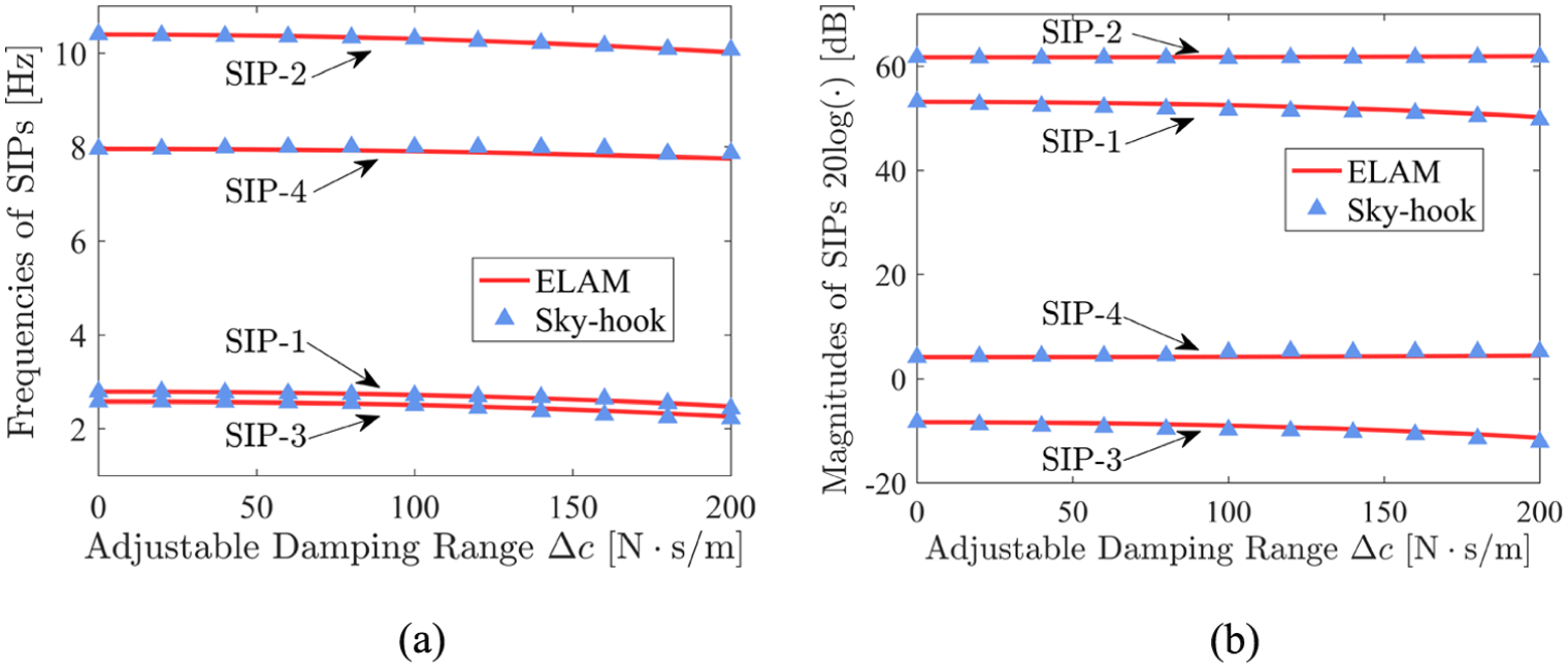
Comparison of results between ELAM and sky-hook under different Δc: (a) frequencies of SIPs and (b) magnitudes of SIPs.
In addition, some facts of ELAM should also be noted:
The ELAM is just an approximate model of the semi-active suspension to derive SIPs. Its essence is the passive suspension which is fundamentally different from the semi-active suspension. Moreover, the ELAM is unprocurable in practice for its soft stiffness which could hardly hold the chassis static load in practice.
The ELAM is universal to linearize different semi-active suspensions. However, every control algorithm has a corresponding equivalent stiffness
In this study, the main function of ELAM is to derive the expressions of SIPs as well as study the properties of SIPs. However, the ELAM could reflect many characters of SIPs. Hence, potential functions of ELAM are worth exploring in the future.
Influence of SIPs on vehicle performance
To analyse the influence of semi-active suspension on vehicle performance, two theorems on the properties of SIPs are introduced first. Then, some discussions about the adjustable damping range are conducted to provide insight for the damper optimization.
Important theorems on SIPs
Theorem 1
For the sky-hook semi-active suspension, the frequencies of SIPs decrease as the adjustable damping range Δc increases, namely

Proof
The following equation can be obtained by substituting

Then, the following equation can be derived by performing derivative about

It is easy to prove the following inequation

Given in equation (24), the following relationship can easily be derived from equation (23)

Therefore, given equation (11), it is obvious that

Consequently, the following relationship can be obtained by combining equation (25) with equation (26)

The other relationships involved in Theorem 1 can also be derived with the above method.
Theorem 2
For the sky-hook semi-active suspension, the magnitudes of SIP-1 and SIP-3 increase with the adjustable damping range Δc. Meanwhile, the magnitudes of SIP-2 and SIP-4 decrease as the adjustable damping range Δc increases, namely

Proof
The invariant point FIP-2 is located between the two resonance peaks with the approximate frequency of 4 Hz in most vehicles. 16 Moreover, the frequencies of SIPs are near the two resonance frequencies. Hence, it is obvious that

Then, the following relationship can be obtained by substituting

Therefore, the magnitude expression of SIP-1 can be rewritten as

Then, the following equation is obtained by performing derivative about ωS – 1 on equation (31)

Given Theorem 1, then the following relationship can be obtained

The other relationships involved in Theorem 2 can also be derived with the above method.
If the adjustable damping range Δc is given, the frequencies and magnitudes of SIPs are determined. From Figure 6, it can be seen that the SIPs limit the performance of the sky-hook semi-active suspension, especially SIP-1 and SIP-3. To further study the effect of SIPs on vehicle performance, a group of simulations are conducted with the different Δc. From Figure 8, some interesting conclusions can be drawn:
With the increase of Δc, the frequencies and magnitudes of SIP-1 and SIP-3 all decrease rapidly. This phenomenon means that the limitation around the first-order resonance will be weakened with the increase of Δc.
With the increase of Δc, SIP-2 gets closer to FIP-1. This phenomenon means that the two limit points (SIP-2 and FIP-1) around the second-order resonance turn into one limit point (SIP-2 overlaps FIP-1) as the Δc value increases, which is beneficial to ride qualities around the second-order resonance.
With the increase of Δc, the frequency of SIP-4 decreases slowly while the magnitude increases. From Figure 8(b), it can be seen that the increase of the magnitude will lead to bad road-holding around the second-order resonance.

Influence of SIPs on the concerned transfer properties: (a) sprung mass acceleration and (b) tyre deflection.
In conclusion, the increase of Δc improves ride qualities while weakening road-holding in the sky-hook semi-active suspension. This property provides insight for the optimization of Δc for different demands.
Influence of SIPs on suspension optimization
It can be seen from section ‘Important theorems on SIPs’ that the larger adjustable damping range Δc is conducive to suspension performance. But in practice the development costs of adjustable dampers increase with the damping range. Besides, the adjustable damping range is clearly unable to be infinity in reality. Hence, it is expected to clarify the proper damping range for the best suspension performance that could be achieved.
At present, a large number of studies9,10 indicate that the small stiffness of the passive suspension can reduce sprung mass vibration, which is good for ride comfort. If the suspension is extremely soft (namely, the stiffness is 0 N/m), the vehicle body could be motionless in the vertical direction, which is unrealistic. In addition, the soft suspension increases the probability of the end-stop collision which is bad for the ride comfort. The ELAM presented in this study is a fictitious approximation model, which is designed to simulate the motion of the semi-active suspension. Therefore, the suspension stiffness of ELAM could be extremely soft by changing the adjustable damping range Δc; meanwhile, the suspension could support the vehicle body as a normal passive suspension.
When

In this case, the ELAM can be expressed as shown in Figure 9.

The ELAM
The motion equations can be written as

The transfer function from the road excitation to sprung mass acceleration can be expressed as

The magnitude of the transfer function can be derived as
where
When
At this frequency, the point on the frequency responses of vehicle body acceleration is FIP-1.
When

where

Hence, it can be concluded that the value of
Accordingly, when
When
SIP-1
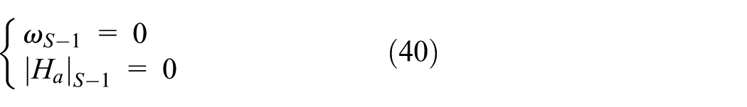
SIP-2

As shown in the above expressions, the invariant point SIP-1 overlaps the origin, while SIP-2 overlaps FIP-1. When the invariant point and the origin or two invariant points overlap, the two constraints turn into one. This is conducive to the vehicle dynamics performance. For simplification, the frequency range between SIP-1 and FIP-1 is defined as Range A (RA), and the frequency range beyond SIP-2 is defined as Range B (RB). As shown in Figure 2, the smaller Λc is needed to achieve better ride comfort in both RA and RB. Interestingly, when SIP-1 overlaps the origin and SIP-2 overlaps FIP-1, RA and RB take up the whole frequency domain. Hence, when
Experimental study
In theoretical study, some vehicle properties are assumed as linear, such as suspension damping and stiffness. Nevertheless, in practice, the performance of suspension can be influenced by the nonlinear characteristics of the damping force, dynamics of the solenoid valve, nonlinear suspension stiffness and so on. Although invariant points have been studied for years, they are never validated in real working condition. Hence, a scaled quarter vehicle test rig is developed in this study to validate the invariant points in the real working condition.
Experiment setup
The structure of the test rig is shown in Figure 10. The road is simulated by an aluminium board which is connected to an electric actuator. The sprung and unsprung mass are also simulated by aluminium boards, and they are weighted with iron blocks. The stiffness of suspension and tyre is provided by springs. A magnetorheological (MR) damper is employed to generate the semi-active control force. Three microelectromechanical system (MEMS) accelerometers are attached to the road, unsprung and sprung boards. A linear encoder sensor is mounted between the unsprung mass and road to measure tyre deflection. A National Instrument PCI-6229 data acquisition board is utilized to implement data acquisition. The sampling time is set to 0.001 s. Arduino® Mega microcontroller is employed as an electronic control unit to host the semi-active control algorithm. The parameters of the scaled quarter vehicle test rig are given in Table 2. Note that the tyre damping is also neglected in the test rig to approximate the simplified quarter vehicle model.

Scaled quarter vehicle test rig.
MR damper
An MR damper is developed for the SIP experiment, as shown in the lower right image in Figure 10. A driver is designed to supply current to the MR damper, as shown in Figure 11. The MR damper is tested for its steady-state dynamic properties with a sinusoidal velocity excitation at an amplitude of 0.4 m/s. The current applied ranges from 0 to 0.8 A. As shown in Figure 12, the MR damper presents obvious nonlinear hysteresis properties. Meanwhile, the damping force shows current-related property. The aim of the experiments is just to validate the invariant points, so a precise damper model is unnecessary in this study.

MR damper driver.
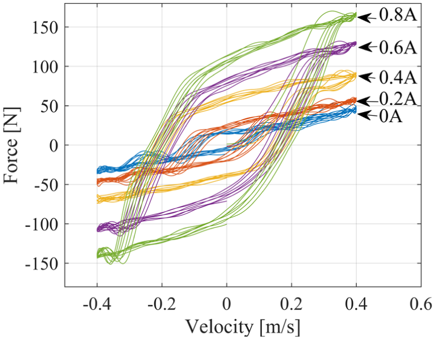
Force versus velocity property of MR damper.
Experimental results
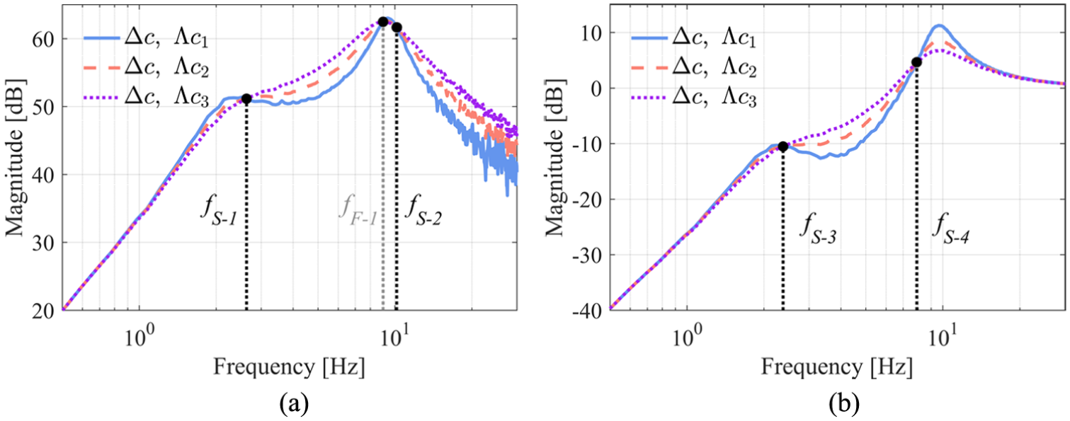
The MR damper with different applied currents is used to provide different damping. Figure 13 shows the two concerned frequency responses of passive suspensions, and Figure 14 shows those of sky-hook semi-active suspensions. Interestingly, all the three kinds of invariant points can be observed in the experimental results. This phenomenon indicates that the invariant points still exist even if nonlinear properties are included in practice. Hence, it can be concluded that the invariant points are real, not just exist in the theoretical analysis. In addition, as shown in Figure 13, the influence of different Λc values on the magnitudes is not significant before SIP-1 and SIP-3, which agrees with the simulation in Figure 2. The results of simulation, experiments and ELAM are presented in Table 3. In Table 3, the errors between ELAM and simulations (experiments) are defined as follows

Experimental frequency responses of passive suspensions: (a) sprung mass acceleration and (b) tyre deflection.

Experimental frequency responses of sky-hook semi-active suspensions: (a) sprung mass acceleration and (b) tyre deflection.
The SIPs of simulation, experiment and ELAM.
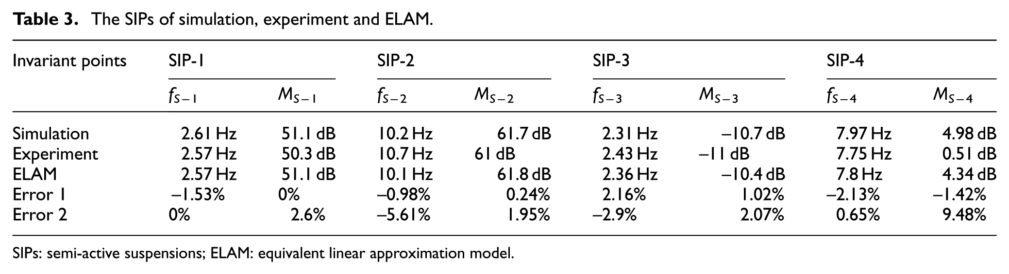
SIPs: semi-active suspensions; ELAM: equivalent linear approximation model.
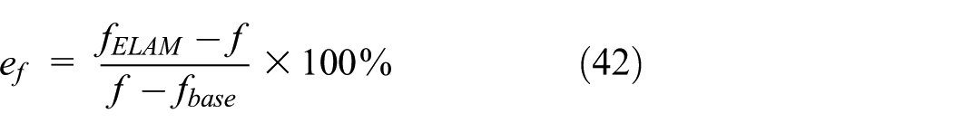

where fELAM is the SIPs’ frequencies derived by ELAM, f is the SIPs’ frequencies from experiments or simulations, fbase is the base frequency, which is 0 Hz in this study, MELAM is the SIPs’ magnitudes derived by ELAM, M is the SIPs’ magnitudes from experiments or simulations and Mbase represent the base magnitudes, which are 20 and −40 dB corresponding to Ha(s) and Htd(s), respectively. As shown in Table 3, the SIPs’ frequencies obtained from simulation and ELAM are in good agreement with the experimental results. However, there still exist differences which may be caused by nonlinear properties, sampling time, errors of data processing and other uncertainties in practice. In Table 3, Error 1 represents the errors between ELAM and simulations. It is obvious that all the errors range between −2.5% and 2.5%. Error 2 represents the errors between ELAM and experiments. Most of the errors are small except the ef at SIP-2 (−5.61%) and eM at SIP-4 (9.48%), which might be caused by the uncertainties in experiments. With regard to ELAM, the imprecise coefficient λ is the main cause of errors. Therefore, a larger number of simulations n or other identification methods could be adopted to reduce the errors. Comparing Error 1 and Error 2, it can be concluded that ELAM is a proper model to derive the expressions of SIPs.
Conclusion
In this article, the invariant points of semi-active suspensions (SIPs) are studied. To analyse the SIPs, an ELAM is proposed to linearize the semi-active suspension. With the ELAM, the expressions of SIPs are derived, which throw light on the influence rule of the adjustable damping range on semi-active control. At last, the existence of invariant points is validated through the experimental study. The main conclusions are as follows:
SIPs are invariant points that exist only in semi-active suspensions. Meanwhile, the passive suspension invariant points (LIPs) could be considered as an extreme case of SIPs when the adjustable damping range Δc equals 0 N s/m.
SIPs are independent of Λc (the sum of maximum and minimum damping), while they are dependent on the adjustable damping range Δc. The frequencies of all the SIPs decrease as Δc increases. However, the magnitudes of SIP-1 and SIP-3 decrease as Δc increases, while those of SIP-2 and SIP-4 increase with Δc. As a conclusion, the proper adjustable damping range and a small minimum damping are beneficial to vehicle dynamics performance.
For the sky-hook SIP, the ride comfort could be improved throughout the frequency domain by reducing Λc when the adjustable damping range equals
The existence of the invariant points is proved by experiments in nonlinear conditions, including FIPs, LIPs and SIPs. This result shows that the invariant points are real, not just exist in the theoretical analysis.
In future, more general properties of SIPs in different semi-active suspensions will be explored.
Footnotes
Appendix 1
Handling Editor: ZW Zhong
Declaration of conflicting interests
The author(s) declared no potential conflicts of interest with respect to the research, authorship and/or publication of this article.
Funding
The author(s) disclosed receipt of the following financial support for the research, authorship and/or publication of this article: This work was supported by the National Key Research and Development Program of China (No. 2018YFB0104804), and China Automobile Industry Innovation and Development Joint Fund (No. U1664257).