
Abstract
Large-sized non-asbestos brake pad is used in the brake system of mine hoister. During the braking process, uneven contact force distribution in the contact surface will occur, which accordingly leads to uneven wear and a shortened service life of the brake pad. To reveal contact force variation laws of large-sized brake pad during the braking process, using the software package ADINA, the braking process was simulated in this work. The results show that (1) the contact forces gradually present saddle-shaped distributions along the radial and tangent directions of the disk, and the temperature does not increase with the radius of the disk; (2) the contact forces increase with the nominal normal pressure, but not linearly, and nominal normal pressure should not be higher than 0.6 MPa when the initial speed is equal to 10 m/s; (3) both the contact forces and their increasing speed increase with the initial speed of the disk, but not linearly, and the initial speed should not be higher than 10 m/s when the nominal normal pressure is equal to 0.6 MPa. Correctness of the theoretical analysis was verified by brake experiments. Achievements of this work provide the theoretical basis for optimal design of the large-sized non-asbestos brake pad.
Introduction
Mine hoister is used to transfer materials or people between the bottom of the mine and ground. Being used to stop a mine hoister or control its speed, disk brake plays an important role in ensuring the safety operation. Therefore, braking performance of the disk brake has been all along a research hotspot. Till now, a lot of research has been carried out on tribology characteristics of the disk brake, but most of them are focused on the disk brake used in vehicles.
Dmitriev et al. 1 established a model to study the contact characteristics of friction materials for automotive brakes and analyzed the braking processes of local contacts in an automotive brake system. In the temperature range from ambient temperature to 500°C, Kim et al. 2 measured the thermal diffusivity, the specific heat, and the coefficient of thermal expansion of three kinds of iron alloy series friction materials and two kinds of aluminum alloy series friction materials used for the brake system, and the thermal conductivity was calculated based on the measured thermophysical properties. In order to investigate the hot judder phenomenon of the disk brake system, Jung et al. 3 took the ventilated diskdisk pads, and pistons as the research objects, established three-dimensional (3D) finite element models, and carried out a fully coupled thermo-mechanical analysis using SAMCEF. Aiming at understanding the evolution of the tribological and thermal behavior, Djafri et al. 4 carried out studies to realize an experimental simulation model of the couple disk pads. Lin et al. 5 investigated the non-smooth bifurcations and chaotic dynamics associated with braking systems. At the same time, many other investigations on tribology characteristics of the vehicle’s disk brake were also carried out.6–10
Compared with the vehicle’s disk brake, the disk of the mine hoister brake system is much larger, the diameter of which ranges usually from 1.6 to 2.4 m. At the same time, the brake pad is not metallic, but non-asbestos. For the non-asbestos brake pad, nitrile rubber, and modified phenolic resin are selected as the base material, Kevlar fiber and glass fiber are selected as the reinforced material, and graphite material is selected as the solid lubricant. Meanwhile, feldspar powder, tabular spar, barium sulfate, and sepiolite are selected as the conditioning agent to improve the frictional behavior.
Besides the difference in materials, the geometries are also different. Rectangular brake pads are more frequently used in mine hoister disk brake. Till now, relatively little research has been carried out on non-asbestos brake pad. Aiming at the friction braking problem of mine hoist, Peng et al. 11 investigated the disk brake temperature field variations during the braking process. In order to improve the braking safety of mine hoisters, Bao and colleagues12–15 selected non-asbestos brake shoe of a mine hoister as the frictional material to investigate a frictional phenomenon called “frictional catastrophe” and its mechanisms, and the results show that the friction coefficient of the brake shoe falls suddenly during braking when the temperature is above 300°C. They also selected 16Mn steel and non-asbestos brake shoe as braking pairs and carried out experiments on a pad-on-disk friction tester to reveal their wear modalities and mechanisms. Yin et al. 16 developed a temperature parameter set for characterizing the frictional temperature rise of disk brakes. By matrix categories, Xiao et al. 17 classified friction materials used in vehicles and other industrial equipments, introduced their major components, and analyzed and summarized the advantages and disadvantages of each friction material.
Previous research employed small-sized samples as the object of study, and the contents concentrated on variations of friction coefficient and wear characteristics. The sizes of the samples are usually 25 mm × 25 mm, but the brake pad used in practical applications is usually 210 mm × 300 mm. During the braking process, large thermal elastic deformations will occur and lead to uneven distributions of the contact force and temperature. As a result, the tribology characteristics of the brake pad vary in a large range. Thus, studies on small-sized non-asbestos brake pad cannot reveal the mechanism of the contact between the brake pad and the disk. Taking a large-sized brake pad used in practical applications as the object of study, uneven distribution characteristics of the contact force of the non-asbestos brake pad during the braking process are simulated in this work. Research achievements can provide the theoretical basis for further study of tribology properties and optimal design of the large-sized non-asbestos brake pad.
Mathematical model
Basic equations
The model of the disk brake studied in this work is shown in Figure 1, where the disk is usually fixed to the main shaft of the hoister. Materials of the brake pads are all the same, so only one brake pad is adopted in the disk brake model to reduce the calculation time. Since the brake pad is rectangular, the Cartesian coordinate system is adopted. The 3D heat conduction equation for the disk brake can be expressed as18,19

where λ is the heat conduction coefficient, c is the specific heat, and ρ is the density of the material.

Model of disk brake.
Initial strain caused by thermal deformation can be expressed as 19

where α is the thermal expansion coefficient, T and T0 are the transient and initial temperatures, respectively. For a 3D problem, the initial strain matrix [ε0] can be expressed as 19

where [T] is the nodal temperature and [T0] is the initial nodal temperature.
Boundary conditions
In model building and numerical simulation of the disk brake, the following assumptions are made:
The friction coefficient between the pad and the disk is constant during the braking process.
Material properties are isotropic.
All of the kinetic energy of the hoister is turned into heat by friction between the pad and the disk.
The wear of the contact surface is negligible.
Transient temperatures at the corresponding point of the temporary contact disk/pad friction surface are equal.
The heat, generated due to friction between the pad and the disk, is equally applied to each side of the disk. Thus, along the axial direction, the temperature field distribution should be symmetrical about the middle plane in the disk.
σp is the heat partitioning ratio, which represents the fraction of frictional heat flux entering the pad. σp can be expressed as
where

According to assumption (6), only a half of the disk is adopted in the simulation model. The surface S2 is the middle plane of the disk, as shown in Figure 1.
Boundary conditions at each surface are as follows:
For disk surface S1, the heat flux is assigned in the temporary contact zone, and the heat convection and radiation are assigned in the zone free from friction. The equation is as follows

For the temporary contact zone, ζ = 1. Otherwise ζ = 0.
The heat convection and radiation are assigned in the outer cylindrical surface S3 of the disk and the sides A3 of the pads. The equations are as follows

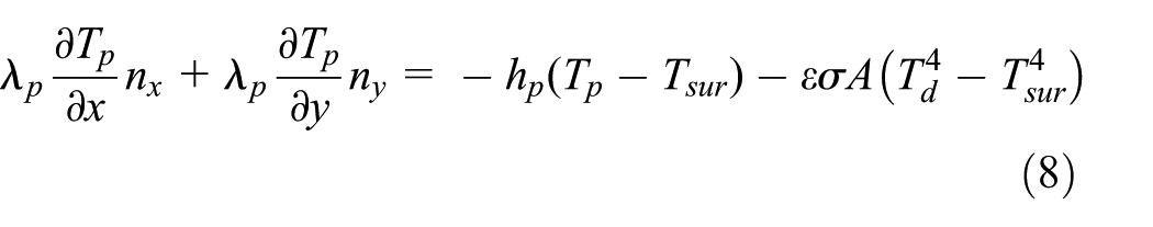
In friction surface A2 of the pad, the heat flux is assigned. The equation is as follows
Since the inner cylindrical surface S4 of the disk is relatively far away from the contact zone, it is assumed to be adiabatic during the braking process. The back surface A1 of the pad has poor heat dissipation conditions since it is fixed to the caliper, so we can also assume that it is adiabatic during the braking process.
Here λd and λp are the heat conduction coefficients of the disk and the pad, respectively; qd and qp are the heat flux values of the disk and the pad, respectively; hd and hp are the convection heat transfer coefficients of the disk and the pad, respectively; Td and Tp are the temperature of the disk and the pad, respectively; Tsur is the ambient temperature, ε the degree of blackness, σ the Boltzmann constant and A is the surface area where the radiation is assigned.
qp and qd can be expressed as 19


where μ is the friction coefficient, Np(x, y, z, t) is the contact force applied to the disk by the pad, ω(t) is the angular velocity of the disk, and ri is the friction radius.
Convection heat transfer coefficient h can be expressed as 19


where Re is the Reynolds number, Pr is the Prandtl number, λk is the thermal conductivity of the atmosphere, and L is the characteristic length.
Simulation procedure
Kinetic equation for mine hoister during the braking process can be expressed as

where ∑m is the equivalent mass to the drum, Fj is the lifting resistance, and Fz is the brake force. When materials are lifted, “–” is adopted in “±”, otherwise “+” is adopted. Fz can be calculated by Fz = μNNp, where NNp is the nominal normal force applied to the brake pad by the thrust cylinder. The nominal normal pressure p applied to the pad can be calculated by the nominal normal force and the area of the pad.
Bao and colleagues12–15 investigated the friction coefficient of the non-asbestos brake pad, and the results show that the friction coefficient of the brake pad varies within a small range when the temperature is below 300°C, which falls suddenly when the temperature is above 300°C. Thus, we concentrate on the braking process during which the temperature is below 300°C. The friction coefficient can be assumed to be constant to simplify the calculation, which is in accordance with assumption (1). Deceleration of the hoist can be calculated by the given value of the nominal normal pressure p, and then the braking time and the angular displacement of the disk can be calculated.
The mathematical model was solved using the ADINA software package. The special boundary condition rigid links is adopted to define angular displacement at the original point. The calculation time step is 0.01 s. The flow diagram is shown in Figure 2. The simulations are carried out under the nominal parameter set and do not reveal the uncertainty of the simulation.
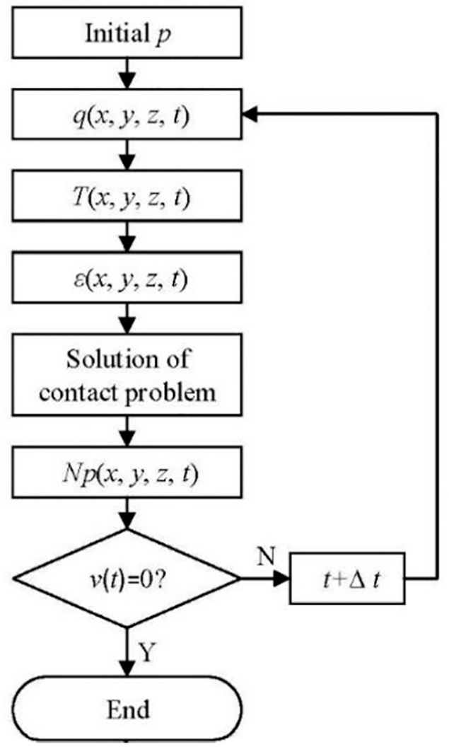
Flow diagram of calculation.
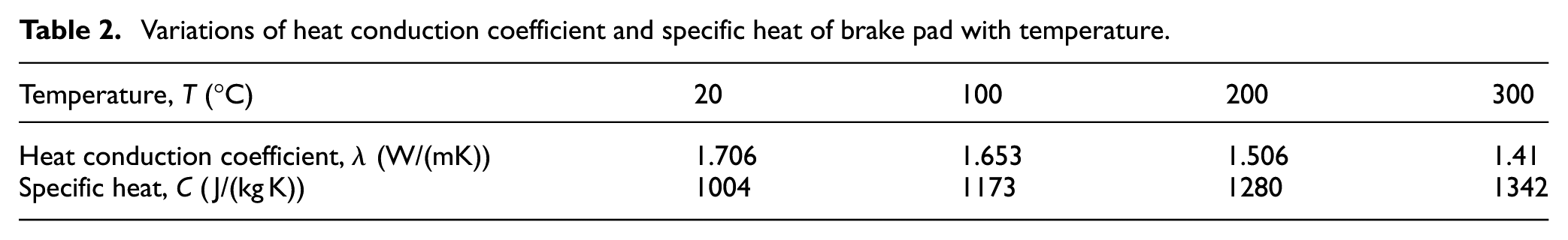
Dimensions, thermophysical properties of the disk and the pad, and working conditions of the disk brake are shown in Table 1. Variations of heat conduction coefficient and specific heat of brake pad with temperature are shown in Table 2.
Input data in calculation.

Variations of heat conduction coefficient and specific heat of brake pad with temperature.
Results and analysis
Variations of contact force
Contact force distribution variations along the x direction of the brake pad during the braking process are shown in Figure 3. It can clearly be seen that the unevenness of the contact force distributions increases gradually with the braking time. From the central point to the edge of the contact surface, the contact forces increase slowly at first and then decrease rapidly. At the edges, the contact force decreases nearly to zero. The maximal values appear in the area near the edge E1. At t = 5.9 s, the contact force at node 35682 increases to the maximal value 213.1 N, which is 127.4 N higher than the average value. At the same time, the contact forces at the four edges are nearly equal to zero. At t = 6.66 s, that is, the end of the braking process, the contact force at node 35682 decreases to 211 N.

Contact force distribution variations of the contact surface along the x direction: (a) t =0.01 s, (b) t = 3 s, (c) t = 5.9 s, and (d) t = 6.66 s.
From Figure 3, it can also be seen that the uneven distribution characteristics of the contact force are influenced by the rotation direction of the disk to a certain extent. The areas where the contact forces decrease first to zero are near the edge E2 and the both edges perpendicular to E1 and E2. The areas where the contact forces are equal to zero increase with the braking time. At t = 6.66 s, the areas where the contact forces are nearly equal to zero cover about 12% of the total contact surface. And the areas near both the edges perpendicular to E1 and E2 are symmetrical about the center of the contact surface. The area, where the contact forces are equal to zero, near the edge E1 is about 60% smaller than that near the edge E2.
Variations of the contact force distribution are mainly caused by the thermal elastic deformation of the brake pad. As inherent properties of the non-asbestos friction material, compressibility and porosity have great influences on the elastic behavior and the absorption of heat of the brake pad, and may lead to further variations of the contact force distribution.
To observe the contact force variations more clearly, Figures 4–6 show the contact force variation laws at different y coordinates in the contact surface. Figure 4(a)–(c) shows the contact force variation laws at different positions on the line (x = 0, z =−135), along the x, y, and z directions, respectively. It can be seen that the distributions of the contact force are relatively even at the beginning of the braking process. At t = 1 s, contact forces in the areas near the both edges perpendicular to E1 and E2 decrease nearly to zero, and the contact forces in the central area decrease to a certain extent. Contact force distributions begin to show a saddle shape. At t = 3 s, the areas where the contact forces are equal to zero continue to increase. The difference between contact forces of the raised part and those of the sunken part of the saddle continues to increase too. At t = 5 s, contact forces in the central area decrease nearly to the values at t = 1 s along the x and z directions, as shown in Figure 4(a) and (c). Meanwhile, the contact forces in the central area along the y direction are lower than those at t = 0.01 s, as shown in Figure 4(b).
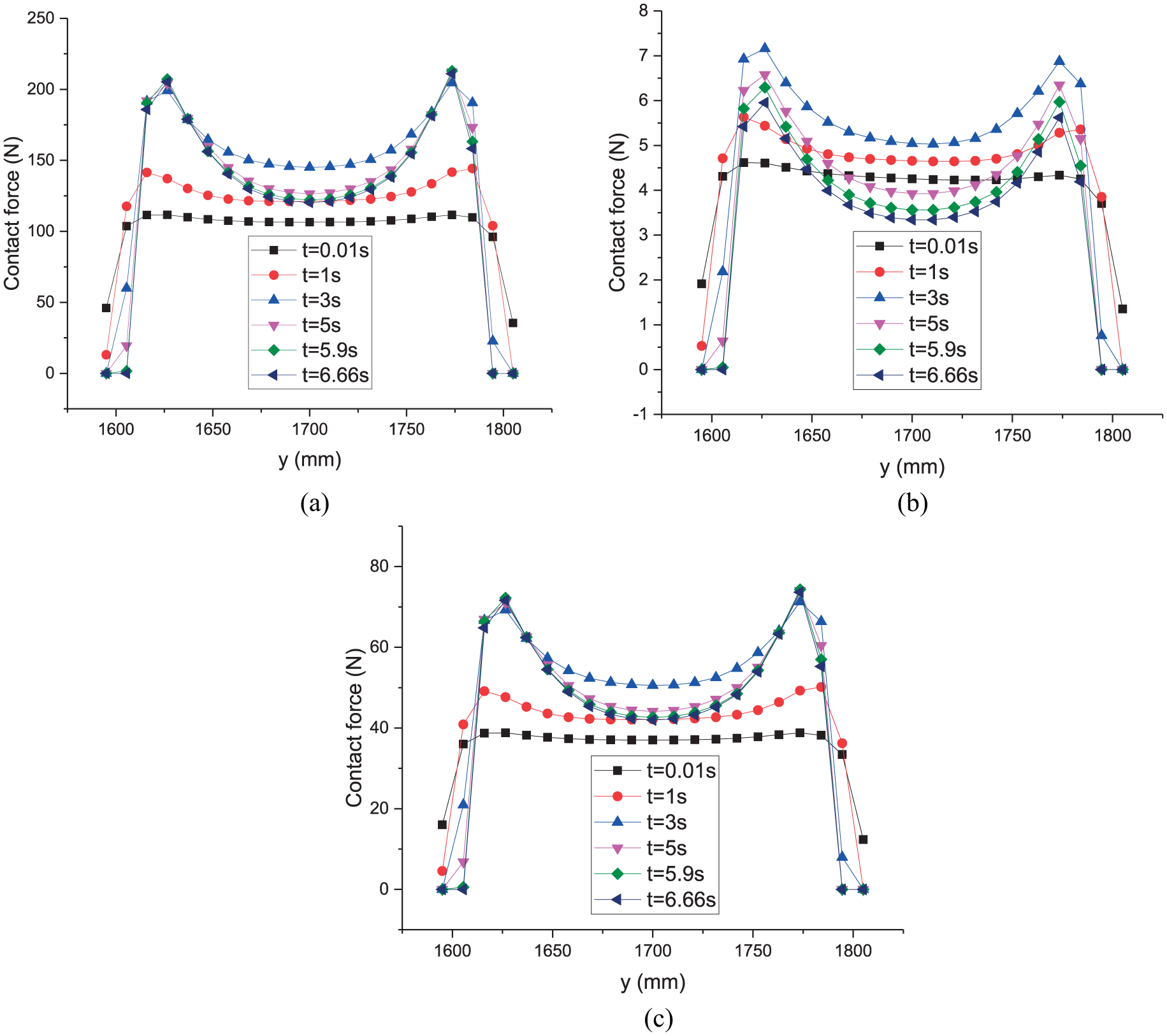
Contact forces at different positions on the line (x = 0, z =−135) (a) along the x direction, (b) along the y direction, and (c) along the z direction.
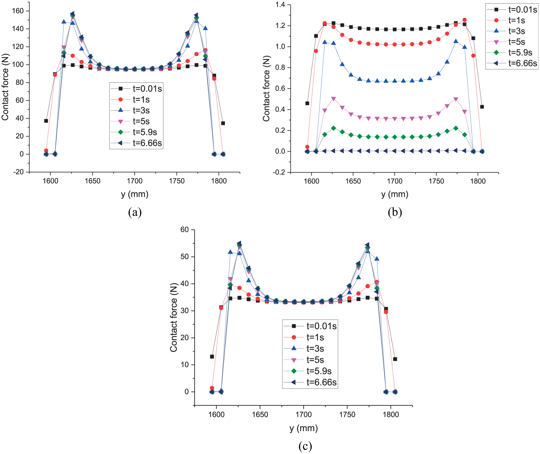
Contact forces at different positions on the line (x = 0, z = 0) (a) along the x direction, (b) along the y direction, and (c) along the z direction.
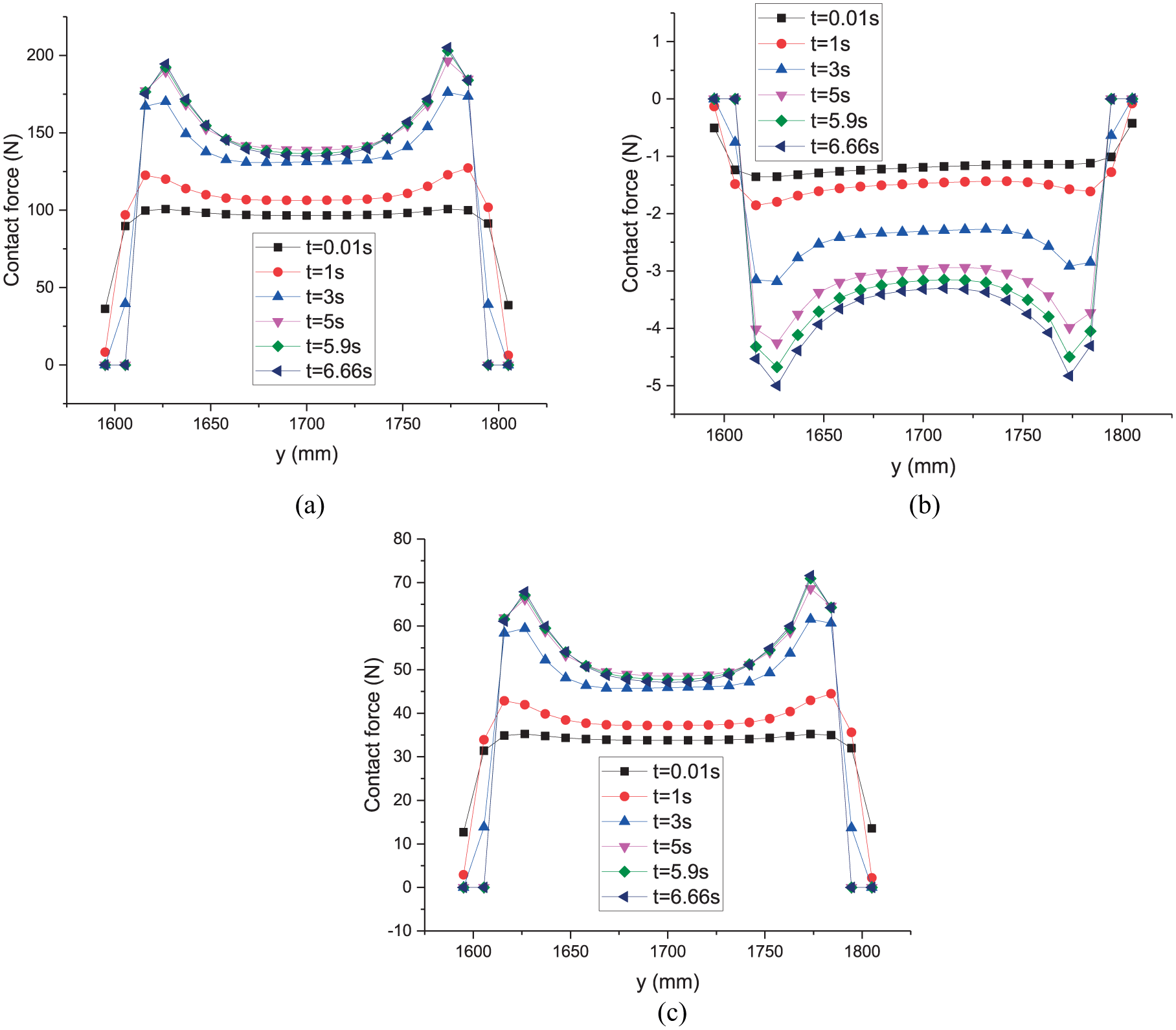
Contact forces at different positions on the line (x = 0, z = 120) (a) along the x direction, (b) along the y direction, and (c) along the z direction.
From Figure 4, it can also be seen that contact forces along the x direction are much larger than those along the y and z directions. Meanwhile, the contact force variation laws along the x and z directions are different from that along the y direction.
Variation laws shown in Figures 5 and 6 are similar to those shown in Figure 4. But in the central area of the contact surface the contact forces along the x and z directions show little variations at different positions on the line (x = 0, z = 0) during the braking process, as shown in Figure 5(a) and (c). The contact forces along the y direction show a decreasing trend, and the differences between contact forces of the raised part and those of the sunken part of the saddle increase at first and then decrease. At t = 6.66 s, the saddle shape becomes nearly a straight line and the values of the contact forces at different positions on the line are nearly equal to zero, as shown in Figure 5(b).
On the line (x = 0, z = 120), the contact forces along the x and z directions show little variations from t = 3 s to t = 6.66 s; meanwhile, the contact forces in the sunken part of the saddle are much greater than those at t = 1 s, as shown in Figure 6(a) and (c). Along the y direction, as shown in Figure 6(b), the values of the contact forces are all almost less than zero. Meanwhile, the variation laws shown in Figure 6(b) are similar to a mirror image of the variation laws shown in Figure 6(a), but the absolute values are much smaller.
Since the contact force at node 35682 reaches the maximal value at t = 5.9 s, it is necessary to study contact force variation laws of node 35682 during the braking process, which is shown in Figure 7. It can be seen that the contact forces along the x and z directions show nearly the same variation laws; meanwhile, the values and variation range are both much higher than those along the y direction. The values of the contact forces along the x direction are maximal, which plays a dominant role in variation laws of the composition of forces.

Contact force variations of node 35682.
At the beginning of the braking process, the contact force along the x direction increases rapidly and reaches a limit value of 205 N at t = 3 s. Then it begins to show a decreasing trend and decreases to 202 N at t = 3.5 s. From t = 3.5 s, it begins to increase slowly again and reaches to the maximal value 213.1 N at t = 5.9 s. Then it begins to decrease slowly again and decreases to 211 N at the end of the braking process.
Temperature variation laws of the contact surface
Variations of the contact force will directly lead to variations of temperature distribution in the contact surface. Temperature distributions in the contact surface at t = 1, 2.8, 6, and 6.66 s are shown in Figure 8. Compared with Figure 3, it can be seen that the temperature distribution has nearly the same variation laws as the contact force, which agrees with the fundamental principle of heat generation by friction.

Temperature variations of the contact surface: (a) t =1 s, (b) t = 2.8 s, (c) t = 6 s, and (d) t = 6.66 s.
When the temperature increases to a certain value, the non-asbestos brake pad begins to degrade and the degradation speed increases with temperature, which will lead to the deterioration of the brake pad.13–15 Then severe wear occurs. Thus, uneven distributions of contact force and temperature can easily result in uneven wear of the non-asbestos brake pad.
Effect of nominal normal pressure on contact forces
Figure 9 shows the contact force variation laws under different nominal normal pressure applied to the brake pad. Figure 9(a) shows the contact force variation laws of node 35682. Figure 9(b) shows the contact force variation laws at different positions on the line (x = 0, z = 0) at t = 2.4 s. Figure 9(c) shows the temperature variation laws of node 35682. When the temperature increases to 300°C, the calculation is stopped as shown in Figure 9(c) and thus Figure 9(a) does not show the contact force variation laws of the whole braking process when the nominal normal pressure p is equal to 0.8, 1, and 1.2 MPa.
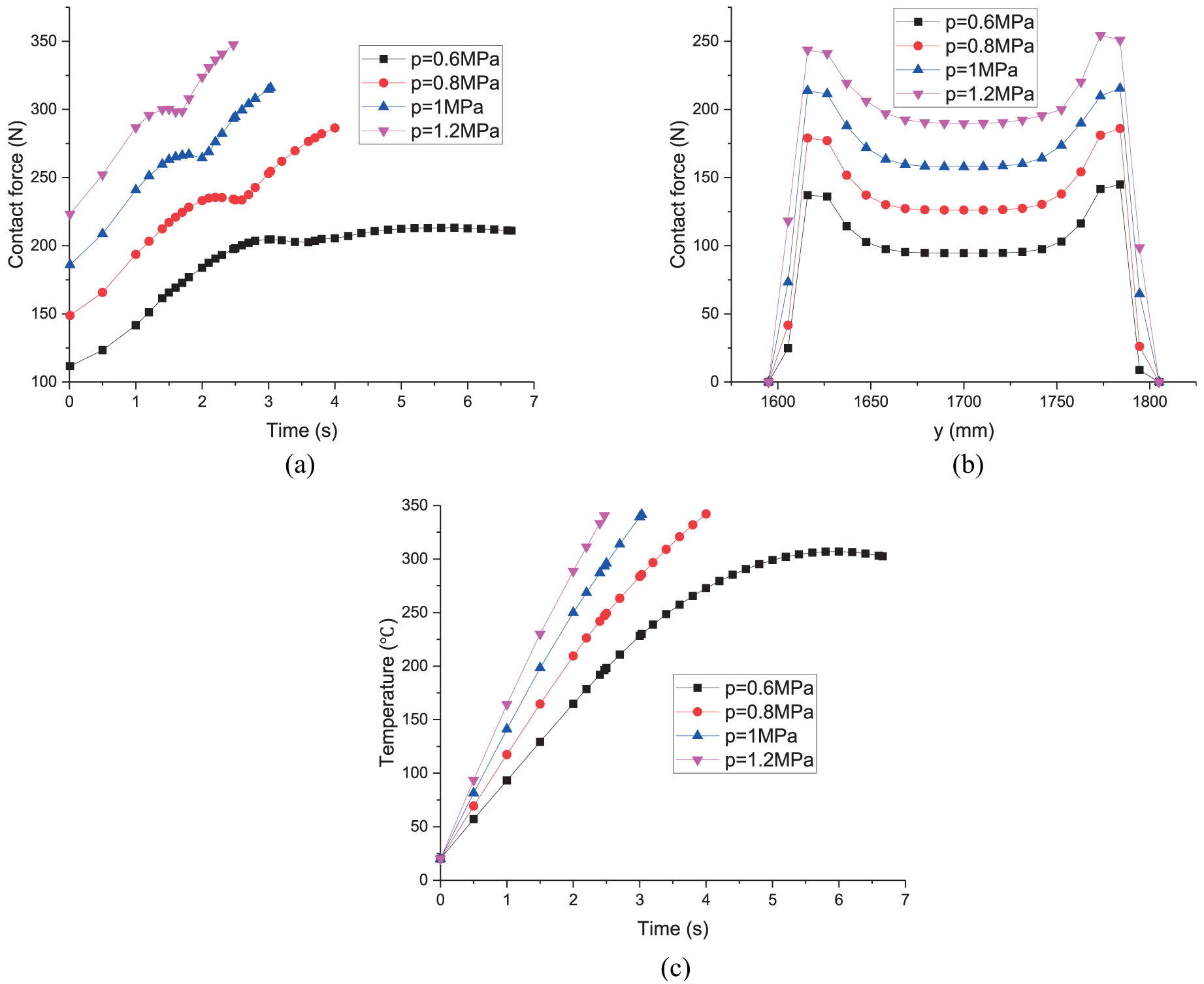
Effect of nominal normal pressure on contact forces: (a) contact force variations of node 35682, (b) contact force variation laws at different positions on the line (x = 0, z = 0) at t = 2.4 s, and (c) temperature variations of node 35682.
From Figure 9(a) and (b), it can be seen that the contact forces increase with the nominal normal pressure, but not linearly. The contact force variation laws under different nominal normal pressure are basically the same. They all increase rapidly at the beginning of the braking process and decrease to some extent after reaching a limit value, then begin to increase again. From Figure 9(a), it can be seen obviously that the increasing speed increases with the nominal normal pressure when the contact forces begin to increase for the second time.
From Figure 9(c), it can be seen clearly that when p ≥ 0.8 MPa the temperature of node 35682 increases to 300°C very soon. Since the non-asbestos brake pad will degrade when temperature is higher than 300°C, nominal normal pressure should not be higher than 0.6 MPa when the initial speed is equal to 10 m/s.
Effect of initial speed on contact forces
The contact force variation laws under different initial speed v0 are shown in Figure 10. The contact force variation laws of node 35682 are shown in Figure 10(a). The contact force variation laws at different positions on the line (x = 0, z = 0) at t = 1.5 s are shown Figure 10(b). The temperature variation laws of node 35682 are shown in Figure 10(c). When the temperature increases to 300°C, the calculation is stopped, as shown in Figure 10(c), and thus Figure 10(a) does not show the contact force variation laws of the whole braking process when the initial speed v0 = 12, 14, 16, and 20 m/s.

Effect of initial speed on contact forces: (a) contact force variations of node 35682, (b) contact force variation laws at different positions on the line (x = 0, z = 0) at t = 1.5 s, and (c) temperature variations of node 35682.
From Figure 10(a), it can be seen clearly that the contact forces increase with the initial speed and the contact force variation laws of node 35682 under different initial speed are basically the same. The increasing speed of the contact forces also increases with the initial speed, especially when the contact forces begin to increase for the second time.
From Figure 10(b), it can be seen that the contact forces in the central area of the contact surface show little variations. In the areas between the central area and the edge of the contact surface, the contact forces increase with the initial speed. In the area near the edges, the contact forces decrease with the initial speed.
From Figure 10(c), it can be seen that when the initial speed v0 ≥ 12 m/s the temperature of node 35682 increases to 300°C very soon. Since the non-asbestos brake pad will degrade when the temperature is higher than 300°C, the initial speed v0 should not be higher than 10 m/s when the nominal normal pressure is equal to 0.6 MPa.
Brake experiments
Taking a non-asbestos brake pad as the research object (25 mm × 25 mm), Zhu et al. 14 studied the temperature rise characteristics of the brake pad. The results show that the temperatures increase with the radius. It can clearly be seen that it exhibits a big difference from the calculation results of this work, as shown in Figure 8.
In order to verify the correctness of the theoretical analysis of this work, experimental equipment were developed and a number of experiments were carried out using a large-sized brake pad (210 mm × 300 mm). Figure 11 shows the schematic of the experimental equipment, where the input shaft of the reducer is connected to the output shaft of the hydraulic motor by means of the coupler A. Output shaft of the reducer is connected to the brake disk by means of coupler B. The hydraulic motor and the brake calipers are both controlled by the hydraulic control system. The brake calipers are spring applied and hydraulic released. Figure 12 shows the experimental equipment, where E2 is the opposite edge of E1, as shown in Figure 1.
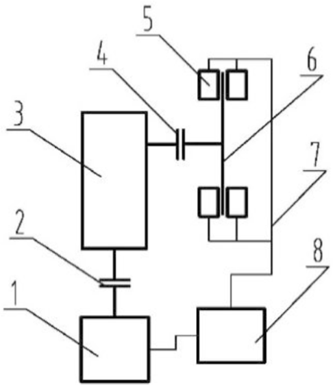
Schematic of the experimental equipment.

Experimental equipment.
Displacement of the hydraulic motor is 593 mL/r and the working pressure is 15 MPa. The gear ratio of the reducer is 20. Rated brake torque of the disk brake is 28.5 kN m. The braking process is as follows: at first the brake caliper is released and the hydraulic motor drives the disk to rotate. Then the hydraulic pressure of the brake caliper is released and the brake caliper begins to stop the disk. At the end of the braking process, the disk and the hydraulic motor are both stopped.
From Figure 13, it can be seen that the brake pad after the braking process was repeated 50 times. It can be seen that although severe wear has not occurred, uneven wear can be observed obviously. In the areas near the edges E1 and E2, wear loss is relatively larger, which covers less than 50% of the total contact surface. In the central area, only slight wear occurs. The areas near the edge perpendicular to E1 and E2 remain nearly unworn. Wear loss is proportional to the contact force. Thus, the experiments verify the correctness of the theoretical analysis of this work.
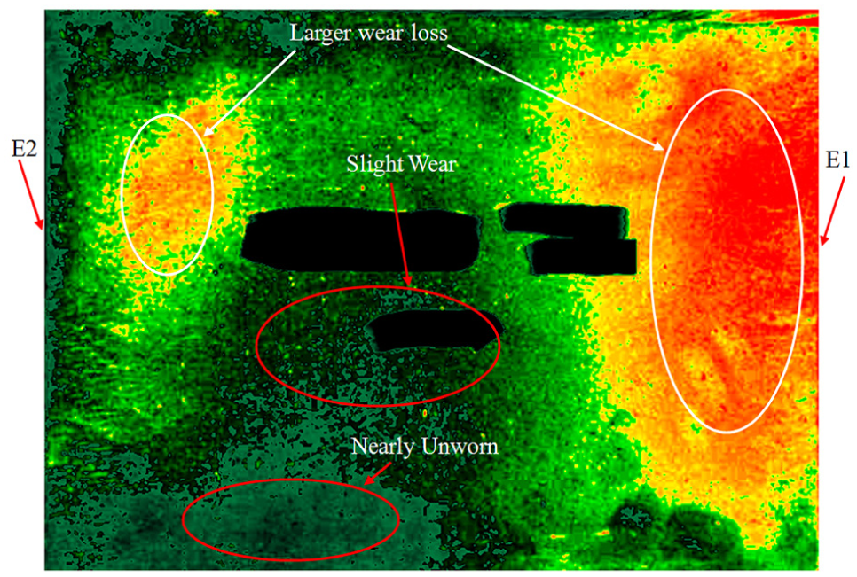
Brake pad used in experiments.
Uneven distributions of contact force and temperature will lead to variations of the friction coefficient of the brake pad and eventually deteriorate the working performance of the disk brake. Thus, a large-sized non-asbestos brake pad should be adopted to study the tribology characteristics of the brake pad used in practical application.
Conclusion
The contact force distributions in the contact surface are relatively even at the beginning of the braking process. Then the contact forces begin to show saddle-shaped distributions gradually along the radial and tangent directions of the disk. The variation laws vary within a large range with the positions.
The contact force increases with the nominal normal pressure, but not linearly. The contact force variation laws under different nominal normal pressure are basically the same. Nominal normal pressure should not be higher than 0.6 MPa when the initial speed is equal to 10 m/s.
The contact force variation laws under different initial speed are similar to those under different nominal normal pressure. Initial speed should not be higher than 10 m/s when the nominal normal pressure is equal to 0.6 MPa.
Uneven distributions of contact force and temperature can easily result in uneven wear of the contact surface, which will decrease the working stability of the disk brake. A large-sized brake pad should be adopted in future study on tribology characteristics of the non-asbestos brake pad.
Footnotes
Handling Editor: Jan Torgersen
Declaration of conflicting interests
The author(s) declared no potential conflicts of interest with respect to the research, authorship, and/or publication of this article.
Funding
The author(s) disclosed receipt of the following financial support for the research, authorship, and/or publication of this article: This research was supported by the National Key Research and Development Program (2016YFC0600907).