
Abstract
The free-piston engine generator is a new power machinery, which removes the crank-shaft mechanism. This article aims to study the impact of different injection rate shapes (left triangle, rectangle, and right triangle) on the free-piston engine generator spray and combustion characteristics. An iteration numerical model was established and validated by experiment. The results reveal that there is a positive correlation between injection rate and evaporation rate, and the faster evaporation rate is more conducive to total evaporated fuel mass. The left triangle and rectangle injection modes have the better level of atomization and mixing in the early injection due to stronger turbulent kinetic energy, longer penetration, and smaller Sauter mean diameter, while the right triangle has opposite results, which impairs the mixture formation, and its higher injection pressure in the late injection duration causes more impinged fuel mass. Moreover, the temperature, pressure, peak heat release rate, and indicated thermal efficiency for the left triangle are greater than the other two injection modes. Therefore, for the free-piston engine generator, faster injection rate in the early injection stage enables to improve the fuel evaporation, atomization, and mixing processes, meanwhile enhances the level of isochoric heat release around top dead center, resulting in higher indicated thermal efficiency.
Introduction
In recent years, under the dual stress of saving energy and environmental protection, researchers in the automotive field are paying more attention to the technical improvement and optimization of the conventional engine. In the meantime, they are also exploring the new energy vehicle technology and making efforts to develop new vehicle power plants actively. In this context, a new type of linear hybrid power plant called free-piston engine generator (FPEG) came into being and has attracted more attention of many research institutes around the world, whose prominent feature is the absence of crank mechanism with many potential advantages such as variable compression ratio, simple structure, and wide applicability of multiple fuels.
The research on the FPEG dates back to the 1990s; experts and scholars worldwide have conducted extensive basic researches and applied analysis based on the great potential for electric vehicles; and the research contents relate to the motor control system, piston motion characteristic, combustion and emission characteristics, different combustion modes as well as the impact of external load on the FPEG performance and so on. Zhang and colleagues1–3 have proposed a control method that can accurately control the piston trajectory to ensure the smooth operation of the FPEG, whose effectiveness has been verified by experiments and simulation. Based on the theory, they have also achieved optimization for FPEG thermal efficiency and emission performance. In addition, they also applied this theory to seven renewable fuels and studied the effect of compression ratio and piston motion pattern on the combustion process. Hung and colleagues4–6 studied the influence of key parameters on the operation characteristic of the FPEG by numerical calculation and obtained the conclusion that optimizing key parameters can obtain the better performance of the engine. Moreover, the effects of key parameters on the transition from spark ignition (SI) combustion to homogeneous charge compression ignition (HCCI) combustion were also studied by them. Mikalsen and Roskilly7,8 also made a great contribution to the research of FPEG. They summarized the development history and application status of the FPEG at the present stage and gave a detailed description of the structural characteristic, operation characteristic, and practical application of the FPEG. Subsequently, they also analyzed the basic performance of a free-piston diesel generator as well as the influence of its design parameters and operation variables on the engine performance. Jia et al. 9 ever studied the potential disturbances of a FPEG using a fast-response numerical method and proposed a cascade control strategy as well as a proportional–integral–derivative (PID) control to achieve stable operation of the engine.
From the current researches of FPEG, some differences in combustion performance between the conventional engine and FPEG have been found due to the distinction of piston motion characteristic. Miao et al. 10 found that compared to the conventional engine, the FPEG has longer heat release process and lower peak heat release rate, and similar conclusions have been drawn by Yuan et al. 11 They also conducted an in-depth study on the combustion characteristic of the FPEG and draw a conclusion that the FPEG has relatively short ignition delay period and longer combustion duration; meanwhile, its post-combustion duration becomes more intense. In addition, the in-cylinder gas temperature and pressure of the FPEG are lower than the conventional engine, resulting in the advantage of NO emissions; however, the low indicated thermal efficiency of the FPEG also was found.12,13 As we all know, the injection rate shape has an important influence on the performance of diesel engines, and the reasonable injection rate shape is also the target that researchers are striving for. 14 Currently, some studies relate to the effects of injection rate shapes on the combustion, and emission characteristics of the conventional engine have been reported. Mohan et al. 15 investigated the effect of injection rate shaping on the combustion and emission characteristics of a biodiesel engine by computational fluid dynamics (CFD) simulations. The injection rate shapes were set based on boot length and boot pressure, and a trade-off relation between NO x and soot emissions for long boot length and high boot pressure was found. Jafarmadar et al. 16 studied the effect of three injection rate modes on combustion process in a diesel engine using a three-dimensional CFD model. They found that using the ramp injection rate shape can slightly retard the combustion process and improve combustion performance; meanwhile, lower NO x and soot emissions were found compared to the boot and rectangle injection modes. Shuai et al. 17 also studied the effects of both injection timing and rate shaping on the performance and emissions in a compression ignition (CI) engine. They discovered that employing rectangular-type and boot-type rate shapes can cut down CO, unburnt hydrocarbon (UHC), and soot emissions effectively. Beyond that, there are other works have been done over the recent years to investigate the effect of injection rate shaping on the engine combustion and emission performances.18–22
From the aforementioned works, it can be seen that the research of the impact of the injection rate shape on the combustion process of the conventional engine has been quite mature. In addition, as mentioned above, there are some differences in combustion performance between the conventional engine and FPEG, but the studies on the effects of injection rate shapes on the spray and combustion processes of the FPEG have been limited, so it is unclear how fuel injection rates affect the spray and combustion process of the FPEG. Furthermore, fuel spray plays as a key element on combustion process that strongly affects the exhaust emissions.23–25 Therefore, it is necessary to study the fuel spray to further optimize the FPEG performance. Hence, the objective of this work is to investigate the effects of injection rate shapes on the mixture formation and combustion process of a FPEG fueled with diesel by numerical simulations, which enables us to achieve considerable improvements of combustion process and present the theoretical guidance for spray and mixing of the FPEG in terms of reducing fuel consumption and exhaust emissions.
Fundamental and boundary
FPEG prototype
Figure 1 shows the structure of FPEG, and its main parameters are listed in Table 1. Structurally, it is mainly composed of two free-piston engines, linear motor, load system, and control system. The linear motor is placed between two free-piston engines; meanwhile, the piston and mover of the linear motor are connected together by a rigid rod. The combustible mixture in two combustion chambers alternately burns and expands so as to push the reciprocating motion of the piston assembly. The magnetic lines generated by the permanent magnets arranged on the connecting rod alternately pass through the coil to generate the induced current. In order to ensure the continuous operation of the system and power output, the two-stroke working mode is adopted. In addition, for the precise fuel quality, an electronically controlled common rail fuel injection system is used. Compared with the conventional engine, the FPEG discards the crank-shaft mechanism and has the advantages of simple mechanism, high energy conversion efficiency, multi-fuel adaptability, high energy density, low noise vibration, and high transient response level.26–28

Free-piston engine generator configuration.
Main parameters of the FPEG

Setup of injection rate shapes
Figure 2 shows the rectangle, left triangle, and right triangle injection rate curves applied in the injection period. In view of the fact that the FPEG has no camshaft mechanism, the fuel injection is based on the control of the piston displacement signal. Therefore, to ensure comparability of the spray and combustion processes under the conditions of three injection rate shapes, the same injection position is necessary to be employed. The injection position is 1.51 mm in advance with respect to the nominal top dead center (TDC), and injection duration is 0.86 ms. Furthermore, when setting different injection rate shapes in AVL_Fire software, the amount of injection rates are dimensionless values, which are modified such that the area under the curves for all cases is equal to ensure constant total fuel mass injected in the cycle. 29 At the same time, the initial boundary conditions and injection conditions are the same for the different injection rate shapes to ensure the fairness of the contrast. The specific parameters are shown in Table 2.

Three different types of injection rate shapes.
Initial conditions of numerical investigation.

Modeling and method
Computational mesh model
The piston movement of the FPEG is not mechanically limited by the crank mechanism, but by the resultant force acting on the piston, so the FPEG operation is a result from the coupling effects of combustion and piston motion. Therefore, the modeling method for conventional engines is no longer suitable for the FPEG, whose moving mesh should be established based on the accurate piston motion. However, the accurate piston motion cannot be obtained with one calculation due to inconsistent coupling parameters between combustion process and piston motion. 30 Hence, it is necessary to iteratively calculate the zero-dimensional dynamics model, scavenging model, and the combustion model until the iterative convergence condition is satisfied to obtain the accurate piston motion. The specific iterative process is shown in Figure 3.

Simulation method.
The simulation calculation range starts from the start of effective compression stroke to the end of effective power stroke, so the computational domain of combustion model only contains the cylinder and combustion chamber. According to the structural parameters of the original prototype and geometry of the combustion chamber, the geometric model of the cylinder and combustion chamber is established in the UG software, which is then imported into the AVL_Fire software for meshing, and the moving mesh is generated by using the FAME tool based on the piston motion profile, as shown in Figure 4. In addition, the total number of mesh cells in the whole computing domain is 70686, and all of them are hexahedral. Since the FPEG does not contain the crank-shaft mechanism, the equivalent crank angle (ECA) is used as the time coordinate for the simulation results.

Computational grid of simulation.
Numerical models
The numerical models built in this article mainly include the spray model and the combustion model, which can be used to simulate the fuel breakup, turbulence dissipation, evaporation, mixing, and combustion accurately.
Spray model
In this article, the Wave Standard Model was selected to simulate the droplet breakup process, which is based on the theory of surface wave instability. It defines that the initial change of droplet surface is related to the physical properties and dynamic parameters of injected fuel. 31 Furthermore, droplets begin to be fragmented due to the generation of unstable waves on the liquid jet, which is depended on the wave growth rate Ω and the wavelength Λ, just as the following equations

where, r stands for the instantaneous droplet radius, rstable represents the initial droplet radius, and τa is the breakup time. Besides, the value of C1 is 0.61, and C2 is a constant that characterizes the breakup time of the droplet.
It is difficult to solve the effect of turbulence on the spray particles because of the turbulent interaction among the particles, so the Enable model, a stochastic dispersion method proposed by Gosman and Ioannidis,
32
was used to simulate the turbulence dispersion. In this model, a fluctuating velocity

where k is the turbulent kinetic energy of gas at the particle location, Rni is a random number from 0 to 1, and erf−1 is the inverse Gauss function. Besides, tturb represents the turbulence interaction time which is the minimum eddy breakup time when the particle traverse the eddy, and ε is the turbulent dissipation rate. Cτ and C1 are 1.0 and 0.16432, respectively.
In order to simulate the heat and mass transfer during the fuel evaporation process, Dukowicz evaporation model was employed for simulation, which assumes that the spray droplet has uniform temperature along its diameter, and the physical properties of surrounding fluid are uniform, and certainly, there is a liquid–vapor thermal equilibrium on the droplet surface. The change rate of droplet temperature dTd/dt is determined by the energy balance equation as follows 33

where md is the particle mass, cpd is the specific heat of fuel, dQ/dt represents the convective heat flux transferred from gas to droplet surface, L is the latent heat of evaporation, dfvs/dt stands for local surface heat flux, and dqs/dt represents the vapor mass flux.
Different injection strategies may result in different amounts of fuel accumulating on the cylinder wall or piston as a thin liquid film because of the incomplete evaporation and impingement of injected droplets.34,35 This thin liquid film would affect the evaporation, mixing of spray droplets, and further deteriorate the combustion. Hence, the wall film model was used to simulate the formation of thin liquid film and investigate the effect of impingement under the different injection strategies, including the amount and location of wall film.
Combustion model
The combustion of the diesel FPEG depends on the evaporation, atomization, and mixing of fuel, which are influenced by the injection strategies. Therefore, the ECFM-3Z model, coupled with the spray model, was used to simulate the in-cylinder combustion under the various injection strategies. This model is based on the thermochemical properties of the unburned/burnt mixture under the conditional description, which ensures accurate computation accuracy and good convergence.
Modeling validation
In order to ensure the correctness of the model established in the research, experimental results from the prototype engine were used to compare with simulation results. Detailed descriptions on experimentation and the validation procedures can be found in our previous work. 12 From the comparison between the simulated and experimental results in Yuan et al., 12 it can be seen that the combustion phenomenon is reasonably well predicted by the Fire code, which indicates that the modeling and method were validated well to be used for the description of spray and combustion process in the FPEG.
Results and discussion
Spray development
The fuel spray and atomization processes have an important influence on the mixing and combustion characteristics of the engine, so it is needful to first have a closer look at the respective mixture formation for the three injection rate shapes. It can be observed from Figure 5 that there are differences in the evaporation status of liquid fuel for the three fuel injection rate shapes under the same total fuel injection mass conditions. The evaporated fuel mass for left triangle is 6.56 mg, which is higher than that for other two injection rate shapes, while that for right triangle has minimum value. Figure 6 shows the fuel evaporation rate for three injection rate shapes, and it can be found that the evaporation rate exerts a similar trend with the injection rate. In the early injection stage, the higher injection rate for left triangle makes faster evaporation rate, and the rectangle is in second place. However, the right triangle injection rate shape has faster evaporation rate in the late injection stage; meanwhile, the shorter evaporation duration is also found.
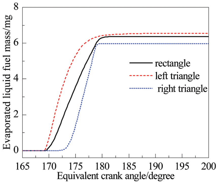
Evaporated liquid fuel mass.
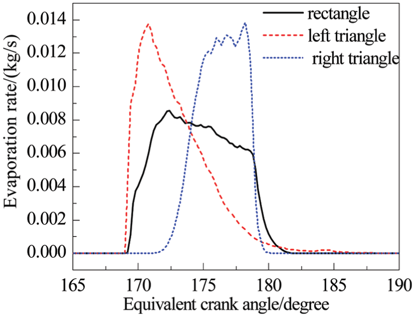
Fuel evaporation rate.
The reason for this phenomenon may be as follows: on one hand, the faster injection rate can speed up the fuel evaporation; on the other hand, the in-cylinder airflow characteristic also has a major impact on the evaporation and atomization condition of the fuel. The turbulent kinetic energy can reflect the intensity of the turbulent motion in the cylinder, and the larger turbulent kinetic energy indicates that the in-cylinder turbulence is more intense, which is more favorable to the mixture formation. As illustrated in Figure 7, the turbulent kinetic energy for left triangle is the strongest under three injection rate shape conditions, which accelerates the fuel evaporation in the early injection stage. As the piston moves close to the TDC, the injection rate for left triangle declines gradually, while the injection rate for right triangle increases continually; at this moment, the in-cylinder turbulent kinetic energy for the right triangle rises rapidly, resulting in the faster fuel evaporation rate in the late injection stage.

In-cylinder mean turbulent kinetic energy.
The Sauter mean diameter (SMD) is an important indicator used to evaluate atomization quality of injected fuel. The smaller SMD makes the fuel atomization level better and is more conducive to the mixture formation. Figure 8 shows the effect of fuel injection rate shape on SMD, and it is found that the left triangle injection mode has the smallest SMD in the early injection stage. It can be seen from Figure 2 that the injection rate for the left triangle is the largest in the early stage of injection, resulting in a higher injection pressure. When the injection pressure increases, the entrainment between the fuel droplets and the surrounding air increases, while the initial crushing particle size of fuel droplets decreases, which facilitate the fuel rapid evaporation and shorten the formation time of mixture, and followed by the rectangle injection mode. For the right triangle injection mode, the SMD in the early injection stage is the largest due to the slower fuel injection rate, which makes the slow fuel evaporation rate in the early injection stage. However, the rapid increasing injection pressure at the end of injection that aims to inject the remaining fuel into the cylinder completely causes the spray droplets to break up quickly and the SMD to decrease rapidly, which also enhances the fuel evaporation rate in the late injection stage.
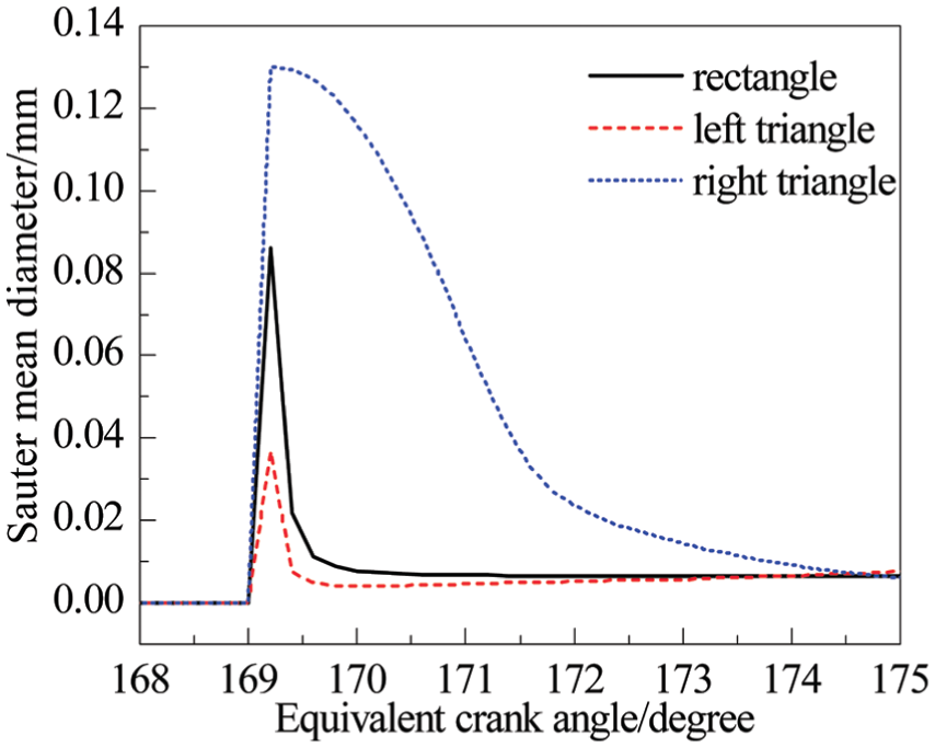
Sauter mean diameter.
The spray penetration can be used to characterize the spatial distribution of fuel injected into the combustion chamber. In the combustion process of diesel engines, it is hoped that the penetration is longer to enlarge the fuel distribution area so as to improve the mixture formation. However, too longer penetration easily causes fuel to collide with the wall, resulting in higher emissions. From the effect of injection rate shapes on the penetration in Figure 9, it can be seen that different injection rate shapes make also the spray penetration different. The penetrations for left triangle and rectangle are longer than that for the right triangle in the early injection stage due to their faster injection rate, which speeds up the mixture formation and improves air utilization. However, when the piston moves close to the TDC, the penetration for right triangle is the longest under the three injection rate shapes due to faster injection rate and stronger turbulent kinetic energy in the late injection stage; meanwhile, its peak value is also the largest.

Penetration.
For small bore engines, the phenomenon of fuel spray impingement is inevitable, which would greatly affect the diffusion, evaporation, and mixing process of the fuel, eventually leading to a reduction of engine performance and an increase in emissions, so it is necessary to decrease the impinged fuel mass as much as possible. Figure 10 shows the impinged liquid mass under three injection rate shape conditions. It is clear that the FPEG adopting the left triangle injection mode has less impinged liquid mass than the other two injection rate shapes. The reason is that, there are a lot of fuel injected into the cylinder before the piston reaches TDC due to the faster injection rate in the early injection stage. When the piston reaches TDC, the injection rate is slow and penetration is relatively short, which results in the least impinged liquid mass. On the contrary, the injection rate for right triangle is slow in the early injection stage but grows continuously, and when the piston approaches TDC, more fuel is injected into the cylinder at a higher injection rate coupled with the rapid increasing injection pressure, resulting in the most impinged liquid mass of all.

Liquid mass impinged.
By comparing the equivalent ratio distribution under the different injection rate shapes of the FPEG in Figure 11, it can be seen that the injection rate shape has a great influence on the mixture distribution in the cylinder. The injection rates for the rectangle and left triangle are faster in the early injection stage, so there is more fuel injected into the cylinder within the same time frame, resulting in relatively large equivalent ratio. Moreover, the center of the mixture concentration for the left triangle reaches the cylinder wall faster, which is in agreement with the result that the penetration for the left triangle is larger in the early injection stage, as shown in Figure 9. However, under the right triangle injection mode, there is relatively little fuel injected into the cylinder due to the relatively low injection rate in early stage, resulting in a lower mixture concentration in the cylinder. With the increasing fuel injection rate, the mixture concentration starts to rise until about 174°ECA, plus the fast-growing turbulent kinetic energy, resulting in faster fuel diffusion. After combustion, the in-cylinder rich mixture for left triangle and right triangle decreases, whereas the rich mixture for the rectangle is left much until 190°ECA. This is mainly because the weaker turbulent kinetic energy makes against the mixing of fuel and air and gives a longer post-combustion phase.
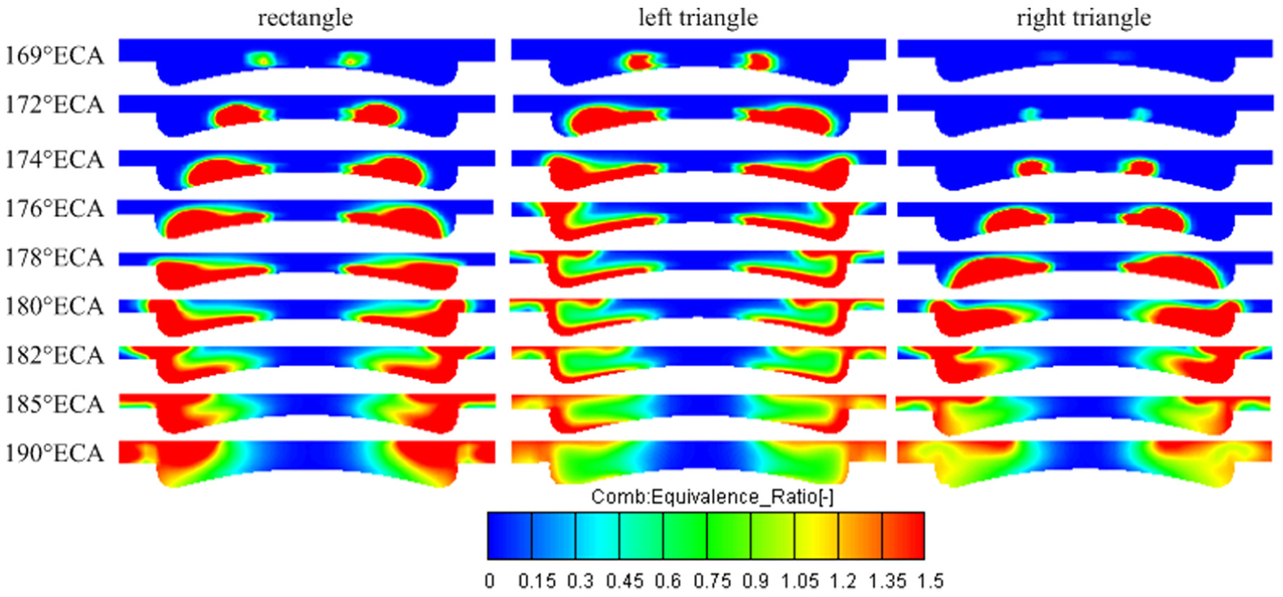
Equivalent ratio distribution in the cylinder.
Combustion characteristic
Figures 12 and 13 show the effects of injection rate shapes on the in-cylinder gas pressure and temperature, respectively. According to Figures 12 and 13, the left triangle injection mode results in the highest peak temperature and pressure due to better mixing level and more combustible mixture formed in the combustion chamber. The right triangle injection mode retards the combustion due to less fuel injected in the early injection stage, weak turbulence intensity, and poor mixing. The combustion timing for the right triangle occurs at 181.4°ECA, at which time the piston has been moving downward at a faster motion velocity, and the volume change rate of cylinder is greater, resulting in a lower peak pressure than that for the rectangle. However, the fuel injection rate for the right triangle is faster in the late injection duration and a larger portion of fuel is injected into the cylinder, resulting in more combustible mixture formed in this period, so the temperature is greater than that for the rectangle. In addition, it can be obtained by calculation that the FPEG using the left triangle injection mode has the highest indicated thermal efficiency of 42.9%, indicating its combustion is closer to an isochoric process, while the indicated thermal efficiency for the rectangle and right triangle are 38.6% and 37.4%, respectively.

In-cylinder gas pressure.
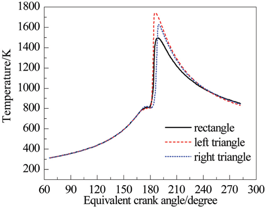
In-cylinder gas temperature.
The ignition delay stage is an important parameter for the combustion process, whose duration obviously affects the amount of premixed gas during the ignition delay period, thus affecting the combustion characteristic, power, and economy performance of diesel engines, so it needs to be precisely controlled. The ignition delay stage is defined as the period between the start of fuel injection and the start of combustion. It can be seen from Table 3 that the order of start of combustion for the three injection rate shapes is rectangle, left triangle, and right triangle under the same fuel injection timing condition, that is, the right triangle injection mode gives the longest ignition delay period, while that for the rectangle is the shortest. The reason for this phenomenon may be as follows: the injection rate and injection pressure for the right triangle are low in the early injection stage, resulting in the largest SMD and shortest penetration, which both are not conducive to the evaporation and mixing process. In addition, the in-cylinder turbulent kinetic energy for the right triangle in the early injection stage is weak, which also induces the longest ignition delay period. It should be noted that the fuel is almost completely injected into combustion chamber during this stage due to the short injection duration for the three injection rate shapes. However, the evaporated liquid mass in ignition delay stage for left triangle is found to be the largest, and followed by the right triangle, as shown in Table 3.
Ignition delay stage for three ignition rate shapes.

ECA: equivalent crank angle.
The instantaneous heat release rates obtained by using different fuel injection rate shapes are shown in Figure 14. As can be seen in Figure 14, the peak value of heat release rate for rectangle is the lowest, and the corresponding phase of peak heat release rate is 184.4°ECA due to the relatively short ignition delay stage and less evaporated fuel mass. Compared to the rectangle, the peak heat release rate for left triangle appears earlier with a higher value. This is mainly because the evaporation rate for the left triangle is faster in the early injection stage and its evaporated fuel mass in the ignition delay stage is more, which leads to more combustible mixture formed in the combustion chamber, so its peak heat release rate is the largest compared to its counterparts. Furthermore, the shortest combustion duration for the left triangle is found, and it also features with the shortest post-combustion period, which can also be seen from Figure 11. It is interesting to note that there are two peak heat release rates for the right triangle injection mode, because less fuel is injected into the cylinder in the early injection stage due to the relatively low injection rate, at the same time the weaker turbulent kinetic energy is not conducive to the breakup and atomization processes of spray droplets, so the first lower peak heat release rate is obtained. However, the evaporation rate for the right triangle gradually increases as the piston approaches TDC, meanwhile the turbulent kinetic energy increases rapidly near the TDC, causing the more combustible mixture to be formed near the TDC, so the second peak value of heat release rate is larger, while the peak heat release rate appears later.

Heat release rate.
Discussions
Different from the conventional engine, the FPEG features with faster piston motion velocity around the TDC and longer post-combustion phase, which have been confirmed in Yuan et al.12,13 As can be seen from the above analysis related to the effect of three injection rate shape on the spray and combustion characteristics of the FPEG, the higher fuel injection rate in the early injection stage is more conducive to improve the FPEG performance. There are majority of fuel injected into the cylinder in the early injection stage due to the fast injection rate. On one hand, the larger injection pressure is beneficial to the breakup, atomization, and evaporation processes of the spray droplets, so that the mixture can be formed faster and better, enhancing the level of isochoric heat release around the TDC and improving indicated thermal efficiency of the FPEG. On the other hand, when most of the fuel is injected into the cylinder in the early injection stage, the piston is far from TDC relatively, so there is less fuel impinged on the wall. Conversely, if the fuel injection rate in the late injection stage is faster, there must be higher injection pressure to ensure that the total fuel is injected into the cylinder completely, but the higher injection pressure will make considerable fuel hit the wall, thereby deteriorating the engine performance. Moreover, when the fuel injection rate is constant, the turbulent kinetic energy in the cylinder is weak. This is not conducive to the evaporation of fuel and mixture formation, but also induces a longer post-combustion period, which also impairs the indicated work of the FPEG.
Conclusion
The research is expected to further optimize the FPEG performance by studying the impact of different injection rate shapes on the FPEG spray and combustion characteristics. From these results and discussions, conclusions of this work are derived as follows:
When injection occurs in the same position, there are differences in the evaporation and spray development under three injection rate shape conditions. The left triangle injection mode gives the faster fuel evaporation rate in the early injection stage because of the faster injection rate and stronger turbulent kinetic energy and followed by that for the rectangle. However, the injection rate and turbulent kinetic energy for the right triangle increase rapidly, resulting in the maximum fuel evaporation rate in the late injection stage. Eventually, the evaporated fuel mass for left triangle injection mode is the most, while that for right triangle mode is the least.
The left triangle and rectangle injection modes have the better level of atomization and mixing in the early injection stage due to the longer penetration and smaller SMD. Besides, the increasing spray penetration and rapidly decreased SMD for the right triangle are found, which is caused by the increasing injection rate. Meanwhile, its liquid fuel mass impinged is the most due to higher injection pressure in the late injection stage.
The left triangle injection mode shows the highest peak in-cylinder gas pressure and temperature of all; moreover, the peak pressure for the right triangle is lower than that for the rectangle due to the greater volume change rate. Conversely, more combustible mixture is formed for the right triangle in the late injection stage, as its temperature is higher than that for the rectangle.
The right triangle injection mode gives the longest ignition delay period, while that for the rectangle is shortest. In addition, the left injection mode shows the maximum peak heat release rate and its indicated thermal efficiency is 42.9%, which is the greatest. Meanwhile, the rectangle injection mode exhibits average results among the three injection rate shapes.
For the FPEG, the faster injection rate in the early injection stage is beneficial. On one hand, the larger injection pressure is beneficial to the breakup, atomization, and evaporation processes of the spray droplets, enhancing the level of isochoric heat release around the TDC and improving indicated thermal efficiency of the FPEG; on the other hand, it can effectively reduce the fuel mass impinged.
Footnotes
Handling Editor: Guian Qian
Declaration of conflicting interests
The author(s) declared no potential conflicts of interest with respect to the research, authorship, and/or publication of this article.
Funding
The author(s) disclosed receipt of the following financial support for the research, authorship, and/or publication of this article: This research was sponsored by the Basic Science and Frontier Technology Research Program of the Chongqing Key Technology Innovation Project of key industries (grant number: cstc2015zdcy-ztzx60014) and the Scientific Research Development Program of Chongqing Jiaotong University (grant number: 15JDKJC-A011). We express sincere gratitude to the sponsors.