
Abstract
Nonlinear friction in a conventional drive feed system feeding at low speed is a main factor that contributes to feed drive complexity. A novel two-axis differential micro-feed system is developed in this study to overcome the accuracy limitation of conventional drive feed system. Instead of the screw-rotating-type ball screw adopted in conventional drive feed system, the transmission component of the proposed two-axis differential micro-feed system is a nut-rotating-type ball screw. In this setup, not only the screw but also the nut is driven by a servo motor. By superposing the two high-speed rotary motions (motor–drive–screw and motor–drive–nut) with an equivalent high velocity and the same rotating direction through the novel transmission mechanism, the nonlinear disturbance from the ball screw can be reduced significantly. In addition, both the axes can avoid the creeping transition zone when the table makes a zero-velocity crossing. Note that the motor load switches when the feeding direction of the table is changed, and the nonlinear friction of the table needs to be compensated. Based on this observation, we further present a cross-coupled intelligent second-order sliding mode control that includes a cross-coupled technology, a second-order sliding mode control, a wavelet fuzzy neural network estimator for the friction, and a motor load switch to improve system performance. The proposed cross-coupled intelligent second-order sliding mode control architecture is deployed on a two-axis differential micro-feed system, where numerical simulations and experiments demonstrate excellent tracking performance and friction compensation capability, achieving position tracking error reduced by 45% compared with conventional drive feed system.
Keywords
Introduction
Feed drive system has become more and more important in the fields of manufacturing, inspection, and assembly. However, friction has a significant and negative effect on the positioning accuracy of a feed drive system. For a typical conventional drive feed system (CDFS) equipped with linear motion (LM) guides and a ball screw, it is difficult to realize accurate and homogeneous displacement at low speeds for the reason that friction frequently generates large tracking errors, undesired stick-slip motions, and limit cycles.1–3 In order to achieve higher accuracy in the position control of the feed drive system, various control techniques for friction compensation have been proposed.4,5 The control methods to friction compensation can be categorized according to their use of friction models.
The model-based approach accurately compensates for the effect of friction on the feed drive by adding an additional driving force equal to the estimated force. Several different friction models (LuGre,6,7 the generalized Maxwell-slip model, 8 Hsieh–Pan 9 ) have been proposed for this purpose. The LuGre model is a relatively favorable friction model by virtue of its more systematic structure and less complex method than those of the other developed models. A friction compensation method using a LuGre-model-based observer was proposed by Zhang et al. 10 Lu et al. 11 presented an adaptive robust control technique using a modified LuGre model for dynamic friction compensation control in a linear motor stage. Various adaptive friction compensation methods that involve observers in accordance with the LuGre model have been presented.12,13
In non-model-based friction compensation methods, the friction is considered typically as disturbance.14–17 Tomizuka 14 proposed a zero-phase error tracking controller, which can substantially reduce the tracking errors induced by friction by eliminating unstable zero dynamics. Su et al. 15 used an extended state observer and a nonlinear tracking differentiator to reduce the disturbance of the 6-degree-of-freedom (dof) Stewart platform system. Lin et al. presented a robust controller that combines a variable structure controller and a disturbance observer (DOB), 16 which could observe a disturbance, as well as frictional force. 17 However, the DOB method may encounter robust problems when friction parameters vary significantly. It is also necessary to consider uncertainties, such as parameter changes and modeling errors, to achieve accurate tracking performance. These uncertainties can be approximated well by fuzzy or neural network (NN) schemes.
Fuzzy systems and NNs have been used to handle unknown nonlinearities and disturbances, as well as identify and control complex systems. Fuzzy neural networks (FNNs) inherit the inference technology of fuzzy systems and the learning ability of NNs. 18 Thus, FNNs can approximate nonlinear and uncertain systems.19–21 Meanwhile, the asymmetric membership function (AMF) has been used in several studies to adjust the number of fuzzy rules.22–24 Furthermore, the wavelet neural networks (WNNs) which combine the wavelets with the FNNs have been proposed. Since the wavelets have the properties of time–frequency localization, the wavelet fuzzy neural network (WFNN) with reduced network size can converge quickly and achieve high precision.25–27
However, regardless of the effectiveness of the compensation methods, these approaches cannot reduce the nonlinear friction disturbance of the feed drive system from a source. In this study, a novel two-axis differential micro-feed system (TDMS) is proposed to realize high-precision motion control based on the nut-rotating-type ball screw transmission pair. In the TDMS, the screw and the nut are each driven by a separate motor. By superposing the two rotatory motions (motor–drive–screw and motor–drive–nut) with an equivalent high velocity and the same rotating direction by the differential transmission structure, we reduce the nonlinear friction disturbance from the ball screw significantly. The driven table of the TDMS could obtain a micro-feed with higher precision than that of the CDFS under low speed and especially crossing zero velocity. In addition, both the axes of the TDMS could avoid the creeping transition zone when the table makes a zero-velocity crossing. Notably, TDMS benefits from being driven by two motors simultaneously; thus, the difficulty in system control is increased. The friction of the LM guides must be compensated, and the motor load switches when the table changes the feeding direction. Given this observation, we present a cross-coupled intelligent second-order sliding mode control (I2OSMC) with a WFNN-AMF estimator for frictional compensation and a motor load switch.
The organization of this article is as follows. In section “Modeling of TDMS,” the structural description, dynamic modeling, and frictional analysis of TDMS are given. Meanwhile, the design procedure of the cross-coupled I2OSMC is discussed in section “Control strategy.” In section “Simulations and experiments,” experimental results are presented to illustrate the effectiveness of the proposed TDMS in inhibiting the disadvantageous influence of nonlinear friction. In the same section, the excellent friction compensation performance of the proposed cross-coupled I2OSMC algorithm is also shown. Section “Conclusion” presents the conclusion.
Modeling of TDMS
Structural description of TDMS
The block diagram of the adopted TDMS is shown in Figure 1. The drive feed table is equipped with a nut-rotating-type ball screw and a set of LM guides. A nut-rotating-type ball screw with large balls is selected for the mechanism to eliminate the axial clearance of the ball screw transmission and improve axial rigidity. The screw is driven by a permanent magnet synchronous motor (PMSM). The nut is driven by another PMSM via a timing belt. The two PMSMs have the same parameters. This system adopts two kinds of work modes: differential and conventional drive modes. Under the differential drive mode, the two PMSMs rotate at extremely close velocities and in the same direction. The two macro motions superpose in the differential transmission structure; thus, the driven table can achieve a micro-feed motion with high precision. We maintain the nut-driven axis rotating at a constant velocity to improve the stiffness of the system. The acceleration and deceleration of the table are realized by the acceleration and deceleration of the screw-driven axis. If the table is only driven by the screw-driven axis, this system can be transformed into a CDFS.

Block diagram of TDMS.
Dynamic modeling of TDMS
The dynamic model for a TDMS shown in Figure 2 is given by


where i = 1 and 2 represent the screw- and nut-driven axes of the TDMS, respectively.

Dynamic model of the TDMS.
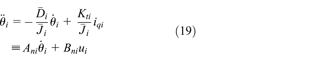
Modeling of the PMSM
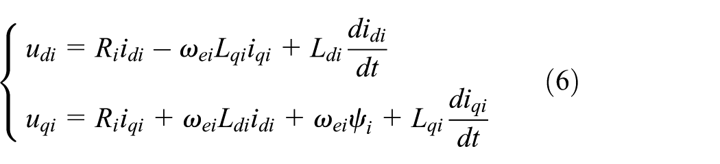
The dynamic model of a PMSM can be described as follows
where
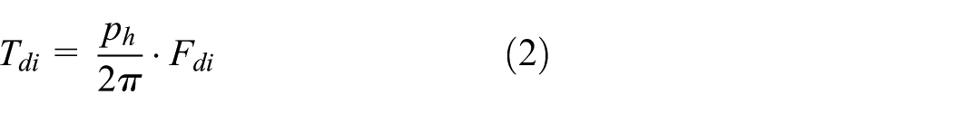
The electromagnetic torque is

We adopt surface PMSM and thus

By implementing the field-oriented control with


where

Modeling and analysis of friction in TDMS
The friction model of the TDMS contains the frictional forces of the nut-rotating-type ball screw and the LM guides each.
3
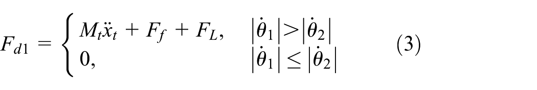
The LuGre models of the two axes


Meanwhile, the LuGre model of the LM guide


where
Figure 3 shows the Stribeck curve of the two axes, where


Stribeck curve of the two axes.
Apparently, as long as the velocity of each axis exceeds the critical velocity, both of the axes are unaffected by the nonlinear friction effect. Therefore, the two axes of TDMS can avoid the nonlinear creeping transition zone when table feeding occurs at an ultralow velocity. Consequently, the position tracking performance of the system can be improved significantly.
In CDFS, when the table needs to change the direction, the drive motor must slow down to zero initially and then accelerate in the opposite direction. This behavior has contributed to the need of the ball screw to pass the impalpable creeping transition zone twice. By contrast, in TDMS, the nut-driven axis can maintain a constant high-speed rotation throughout the feeding process. Then, the screw-driven axis only needs to decelerate to a lower speed than that of the nut-driven axis, allowing the directional change of the table. Therefore, both the axes can avoid the creeping transition zone.
Control strategy
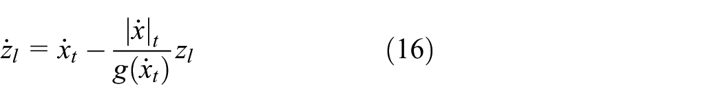
Without considering the external disturbances and the system parameter variations, the function (11) can be rewritten as
where

where

Here, the lumped uncertainty is assumed to be bounded

where
Cross-coupled control strategy
The position tracking error of each macro axis is defined as

where

In TDMS, the micro-feed motion of the table is realized by superposing the macro motions of the two axes. Then, a coupled error

where
Second-order sliding mode control
The sliding surface of the second-order sliding mode control (2OSMC) and its derivation are as follows10,27


The second-order sliding surface is10,27

Taking the derivative of equation (28) and using equation (20), the following equation can be obtained

where
Theorem
Considering the system dynamic equation represented by equation (11), if the proposed 2OSMC law is designed as equation (30), including an equivalent controller (equation (31)) and a hitting controller (equation (32)), then the convergence of the coupled tracking error can be guaranteed by the proposed 2OSMC system


where

Proof 1
Select the following Lyapunov function 27

Invoking equations (21)–(25), the time derivative of

Therefore, the stability of the tracking error
Given the theorem, the switching gain is associated with the lumped uncertainty. However, determining the upper bound of the lumped uncertainty in advance is difficult in practical applications. Thus, an I2OSMC with a WFNN-AMF estimator is developed to estimate the upper bound of the lumped uncertainty. This estimator can alleviate the abovementioned drawbacks. The bound of the lumped uncertainty and the saturation function are not required in the control law. Hence, the stability condition and tracking performance can be improved.
WFNN with an AMF estimator
The WFNN-AMF can handle uncertain information. 27 In this article, the estimator is used for the lumped uncertainty Hi. Figure 4 depicts the network structure of the WFNN-AMF consisting of five layers and the asymmetric Gaussian membership function.
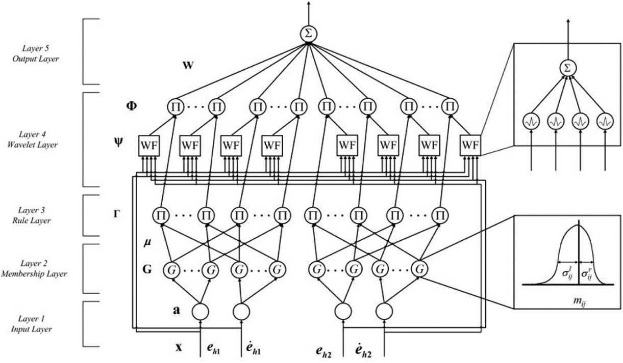
Network structure of WFNN-AMF.
The signal propagation in each layer is introduced as follows 25
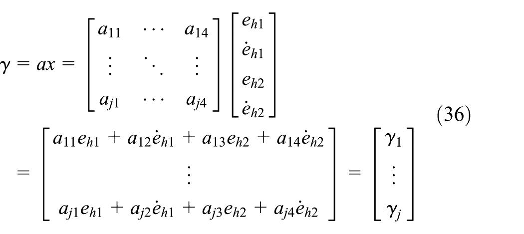
Layer 1 (Input Layer). In this layer, the input state vector of the WFNN-AMF is selected as

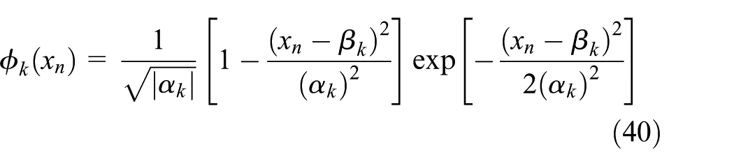
Layer 2 (Membership Layer). In this layer, the asymmetric Gaussian function is adopted as the membership function. For the jth node

where
Layer 3 (Rule Layer). In this layer, the output vector is represented as

where
Layer 4 (Wavelet Layer). In this layer, WF is expressed as
where

The output of the kth node is

Layer 5 (Output Layer). The weight between Layers 4 and 5 is represented as

Cross-coupled I2OSMC
Figure 5 shows the schematic diagram of the I2OSMC system. There is an optimal WFNN-AMF estimator

where

where

where

where

where


Schematic diagram of the I2OSMC system.
Then, equation (48) can be rewritten as

Moreover, we can obtain

Using equations (44), (45), (51), and (52), the approximation error (equation (46)) is modified as

where
Remark
Using equations (23), (24), and (25) and combining equation (38), the I2OSMC is expressed as equation (53). The equivalent control law is designed as equation (54)


Proof 2
Consider the Lyapunov function for I2OSMC as follows 27

where
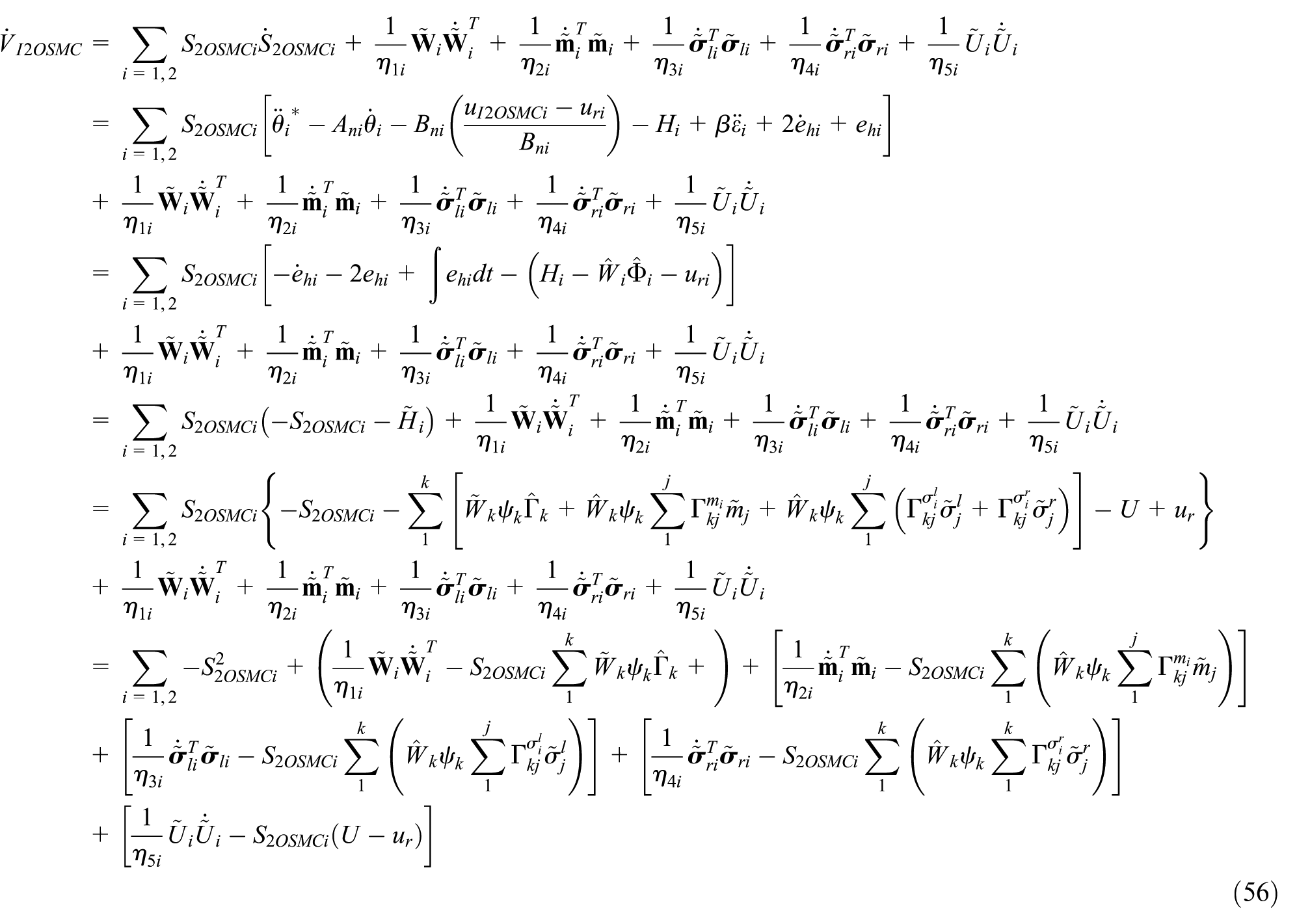
and choose the adaptive laws as


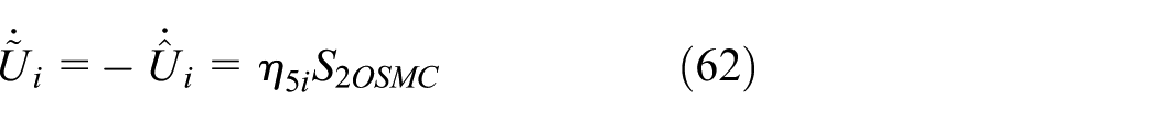
Then

Then integrating equation (63) with respect to time yields

Since

In addition,

Thus,
Simulations and experiments
Simulation results
To investigate the effectiveness of the proposed TDMS in reducing the nonlinear friction disturbance, we perform comparative simulations in both CDFS and TDMS on MATLAB/Simulink. The system parameters are given as Kt = 0.492 N mA, Mt = 20 kg, Ji = 5.83 × 10⁻⁵ kg m 2 , and ph = 5 mm. The parameters of the LuGre model are listed in Table 1. Moreover, for the comparison of the control performance, the 2OSMC and the cross-coupled I2OSMC are all implemented in the simulations. The parameters of the controllers are given as follows: β = 0.5, ρi = 1, Φ i = 0.0005, η1 = 0.1, η2 = 0.012, η3 = 0.05, η4 = 0.056, and η5 = 0.05.
Parameters used in TDMS.

TDMS: two-axis differential micro-feed system; LM: linear motion.
When working in CDFS mode, the table position reference tracking signal is chosen as
Figures 6–7 show the simulation results for the sinusoidal command input of the 2OSMC in CDFS and the 2OSMC in TDMS, respectively. The table tracking responses of the 2OSMC in CDFS and the 2OSMC in TDMS are shown in Figures 6(a) and 7(a), respectively. Figures 6(b) and 7(b) show the control inputs

Simulation results of the 2OSMC algorithm in CDFS: (a) tracking responses of the table for periodical sinusoidal reference trajectory, (b) control input of periodical sinusoidal reference trajectory, and (c) tracking errors of the table for periodical sinusoidal reference trajectory.

Simulation results of the 2OSMC algorithm in TDMS: (a) tracking responses of the table for periodical sinusoidal reference trajectory, (b) control input of the axes, and (c) tracking errors of the table for periodical sinusoidal reference trajectory.
Comparison of the tracking errors in simulations.
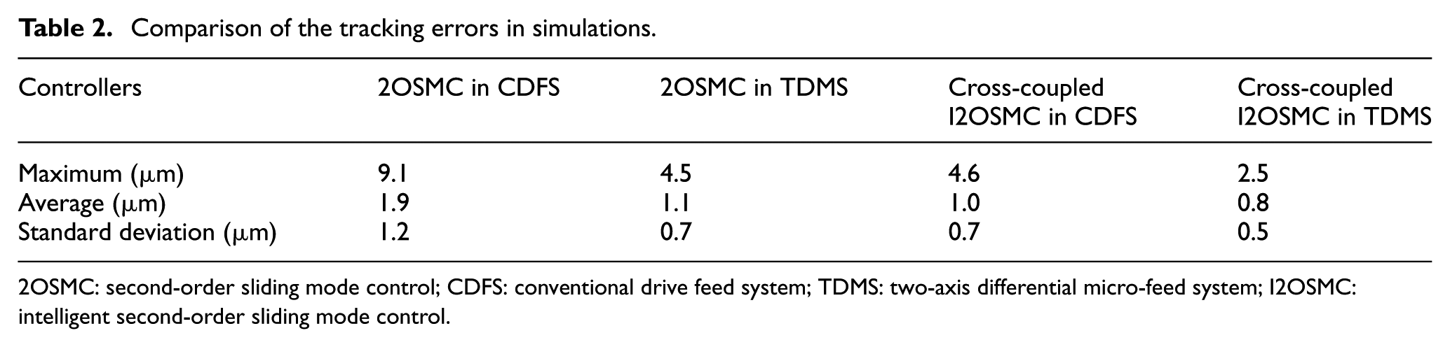
2OSMC: second-order sliding mode control; CDFS: conventional drive feed system; TDMS: two-axis differential micro-feed system; I2OSMC: intelligent second-order sliding mode control.
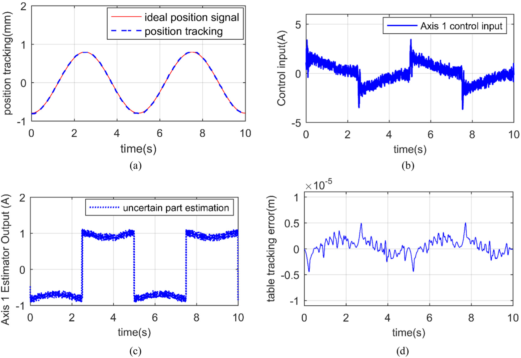
Figures 8–9 show the simulation results for the sinusoidal command input of the cross-coupled I2OSMC in CDFS and the cross-coupled I2OSMC in TDMS, respectively. The table tracking responses of the cross-coupled I2OSMC in CDFS and the cross-coupled I2OSMC in TDMS are presented in Figures 8(a) and 9(a), respectively. Figures 8(b) and 9(b) display the control inputs
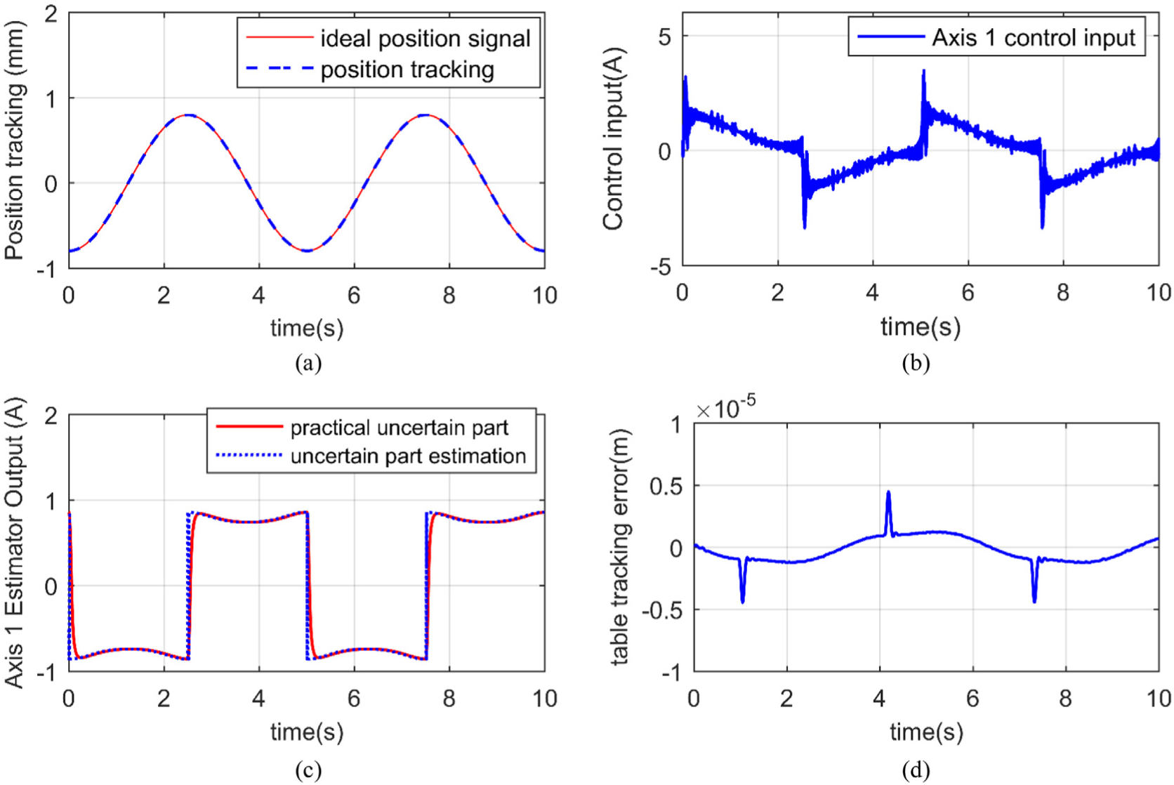
Simulation results of the cross-coupled I2OSMC algorithm in CDFS: (a) tracking responses of the table for periodical sinusoidal reference trajectory, (b) control input of Axis 1, (c) estimator outputs of Axis 1 for periodical sinusoidal reference trajectory, and (d) tracking errors of the table for periodical sinusoidal reference trajectory.

Simulation results of the cross-coupled I2OSMC algorithm in TDMS: (a) tracking responses of the table for periodical sinusoidal reference trajectory, (b) control input of the axes, (c) estimator outputs of Axis 1 for periodical sinusoidal reference trajectory, (d) estimator outputs of Axis 2 for periodical sinusoidal reference trajectory, and (e) tracking errors of the table for periodical sinusoidal reference trajectory.
Experimental setup and results
Experimental setup
Experiments were performed to confirm the results obtained from the simulations. In the experiments, the same control systems like simulation were also designed to investigate the effectiveness of the proposed control system. Figure 10 shows the schematic and photograph of the experimental setup. The feed drive with a stroke of 280 mm was equipped with a ball screw (DIR 1605, THK) with a diameter of 16 mm, a lead of 5 mm, and a set of LM guides (EGH15CA, HIWIN). The ball screw was driven by two PMSMs with a rated power of 400 W (MHMJ042G1D, Panasonic) connected to a servo drive (MBDKT2510CA1, Panasonic). A high-resolution rotary encoder (resolution: 50 nm) is mounted at the back of the motor to provide the feedback of the motor position. A linear scale (Mercury-II-6000, MicroE) with a resolution of 0.1 μm was used to measure the table position. The motors were operated in torque control mode, and the control laws were implemented at 8 kHz sampling frequency on a GTS-800-SV-PCI-G system. The parameters of the controllers were identical to those of the simulations.

Experimental setup.
Experimental results
The experimental results for the sine wave position command input are presented in Figures 11–14. The tracking errors of the two systems are shown in Figures 11(b) and 12(b). The plots illustrate that during the transient periods when the velocity changes the direction during the back-and-forth point-to-point motions, the tracking error peaks shown in CDFS almost disappear in TDMS. Hence, maximum tracking errors are reduced from around 10.1 to 3.1 μm by the proposed TDMS and control algorithm (Figure 14(b)). These results thoroughly demonstrate the effectiveness of the proposed TDMS and the good trajectory tracking ability of our algorithm at low speeds. However, the experimental result differs slightly from the simulated result due to the low stiffness of the timing belt. This problem can be easily solved using direct-drive servo motors in future studies. Finally, the tracking errors of each control system are summarized in Table 3 for an efficient comparison of control performance.

Experimental results of the SMC algorithm driven by screw: (a) tracking responses of the table for periodic sinusoidal reference trajectory, (b) control input of Axis 1, and (c) tracking errors of the table for periodic sinusoidal reference trajectory.

Experimental results of the SMC algorithm driven by TDMS: (a) tracking responses of the table for periodical sinusoidal reference trajectory, (b) control input of the axes, and (c) tracking errors of the table for periodical sinusoidal reference trajectory.
Experimental results of the ISMC algorithm driven by screw: (a) tracking responses of the table for periodical sinusoidal reference trajectory, (b) control input of Axis 1, (c) estimator outputs of Axis 1 for periodical sinusoidal reference trajectory, and (d) tracking errors of the table for periodical sinusoidal reference trajectory.

Experimental results of the ISMC algorithm driven by TDMS: (a) tracking responses of the table for periodical sinusoidal reference trajectory, (b) control input of the axes, (c) estimator outputs of Axis 1 for periodical sinusoidal reference trajectory, (d) estimator outputs of Axis 2 for periodical sinusoidal reference trajectory, and (e) tracking errors of the table for periodical sinusoidal reference trajectory.
Comparison of tracking errors in experiments.

2OSMC: second-order sliding mode control; CDFS: conventional drive feed system; TDMS: two-axis differential micro-feed system; I2OSMC: intelligent second-order sliding mode control.
Conclusion
In this article, we proposed a comprehensive study on the structure, modeling, controller synthesis, and experimental evaluations for a novel TDMS. Based on dynamical modeling and friction analysis, the linear model of the TDMS was derived and the nonlinear dynamics including friction and motor load switch were further taken into consideration. In order to improve the tracking performance of the TDMS, a control structure is developed incorporating cross-coupled technology, a 2OSMC, and a WFNN-AMF estimator. The numerical simulations and experiments showed that the nonlinear friction disturbance in TDMS was reduced significantly compared with CDFS. The timing belt and nut-driven motor can be replaced with a hollow-axle servo motor to further improve the tracking performance of TDMS. This aspect can be considered in future research.
Footnotes
Handling Editor: Jose Antonio Tenreiro Machado
Declaration of conflicting interests
The author(s) declared no potential conflicts of interest with respect to the research, authorship, and/or publication of this article.
Funding
The author(s) disclosed receipt of the following financial support for the research, authorship, and/or publication of this article: This study was supported by the National Natural Science Foundation of China (No. 51375266), the National Natural Science Foundation for Young Scientists of China (No. 51705289), and the Natural Science Foundation of Shandong Province of China (No. ZR2017PEE005).