
Abstract
In small-scale compressed air energy storage system, expansion air engine is the key component. To improve the expansion air energy performance, an innovative kind of two-stage piston type expansion air engine is put forward. In this article, working principles of the new kind of expansion air engine are described. A mathematical model of the working processes is set up by analysis of the air engine. The characteristics of the expansion air engine are obtained by using the simulation technology. Results show that, first of all, with the same supply pressure, the efficiency of the new kind of expansion air engine is higher than that of the single stage expansion air engine by approximately 15%, which is about 1.31–1.56 times of that of the single stage air engine. Simultaneously, the output power of the new kind of air engine is higher than that of the single stage expansion air engine. Second, the efficiency and output power are mainly impacted by the closing angle of valve 1. Third, the bigger the cylinder diameter ratio is, the higher the efficiency is. Finally, the efficiency and output power can reach to the highest value in suitable orifice port shape.
Introduction
Micro-energy network is one of the important developing trends of future energy system. Energy storage (ES) which can mitigate renewable energies such as solar and wind fluctuations is a very important part of micro-energy network. 1 The small compressed air energy storage (CAES) is one of the most significant ES and has received much attention around the world. 2
Expansion air engines which produce mechanical work by consumption of compressed air are the key components of the small-scale CAES system. Many types of expansion air engines have attracted substantial attention,3,4 which included turbomachinery engine, 5 screw engine, 6 scroll engine,7,8 triangle rotor engine, 9 piston-type engine, and so on. Among these air engines, piston-type air engines have a good isentropic efficiency, a high output power and a long life. 10 Thus, it has been given more widely attentions to work on the new energy engine for power generation in small-scale CAES system. 3
In addition, compressed air drives the piston to output work by air expansion in the engine cylinder, and discharges the residual gas. 11 To improve the internal combustion (IC) engine fuel efficiency and reduce pollute emission, expansion air engines is usually as a kind of auxiliary power equipment. 12 Compared with conventional IC engines, this combination of an air engine and IC engine can enhance fuel efficiency by up to 22%. 13 As main power equipment, the single cylinder expansion air engine was studied theoretically and experimentally. The experimental results showed that the efficiency could be more than 25% by using air and the output power reaches 1.92 kW when the intake pressure is set at 2 MPa.14,15 It is obvious that the single cylinder expansion air engine is difficult to satisfy the micro-vehicle engine requirement.
Previous studies are mainly about single-cylinder expansion air engine. Generally, to obtain higher output power, the expansion air engine is operated at 2∼3 MPa. But the high-pressure air in single-cylinder cannot completely expand after the expansion stroke, and air under certain pressure is directly discharged to the atmosphere.
To make full use of the compressed air energy, Liu et al. presented a two-stage expansion air engine which combined with a large cylinder and a small cylinder. The exhaust of the small cylinder flowed into the large cylinder through heat exchanger. The simulating results showed that the performance of two-stage expansion air engine was better than that of a single-cylinder expansion air engine when supply pressure was 10 bar; rotation speed was 1000 r/min. 16 Chi-Min Liu et al. built an experiment to analyze the properties of a two-stage expansion air engine. The experimental results showed that the properties of two-stage expansion engine were superior to the properties of a single-cylinder engine. 17 Compared with a single-cylinder expansion air engine, the two-stage expansion air engine is a better choice to enhance efficiency and output power.
In this article, to improve the efficiency of the expansion air engine more, a new kind of two-stage piston type expansion air engine is proposed. The main difference is that there are four valves in air distribute system, three of which are located on the head of the cylinder, which are driven by camshaft, one of that is situated near the position of bottom dead center (BDC) of one stage cylinder which is opened or closed by the position of piston. On the one hand, the residual pressure air after the expansion stroke in the first stage cylinder is transferred to the second stage, where it carries out another expansion and yields work. On the other hand, the running of the expansion air engine becomes more stable owing to decreasing fluctuation of the torque. Up to now, there is no related study about the new kind of two-stage expansion air engine regarding its power and energy efficiency. This article will carry out simulated study of the air-powered engine’s working process. Both the power and its energy efficiency are obtained. This study analyses the working process and parameters that influence in detail. This study aims to propose a method to enhance the efficiency of expansion air engines by constructing a new expansion air engine with two-stage expansion engine.
The innovative two-stage expansion air engine
Figure 1 shows a new kind of two-stage piston type air-powered engine. The discharge process in the first cylinder is divided into two parts. One part of the residual pressure air from the first cylinder flows into the second cylinder through check valve to make full use of compressed air energy, the other part of residual air from the first cylinder flows out the first cylinder to avoid the compression resistance. To ensure fast response and smooth running, airflow is controlled by using a simple cam mechanism in the two-stage expansion air engine.

Schematic of two-stage expansion engine. 1: one-stage intake valve, 2: one-stage exhaust valve, 3: one-stage piston, 4: one-stage cylinder, 5: two-stage cylinder, 6: two-stage exhaust valve, 7: two-stage piston, 8: check valve, 9: one-stage link, 10: crankshaft and 11: two-stage link.
The proposed engine is developed from the traditional IC engine. The engine consists of an intake valve, two exhaust valves, two power pistons, two cylinders, a check valve, two links and a crankshaft. Figure 2 illustrates the schematic drawing of the proposed engine.
Schematic diagram of the two-stage piston type air-powered engine.
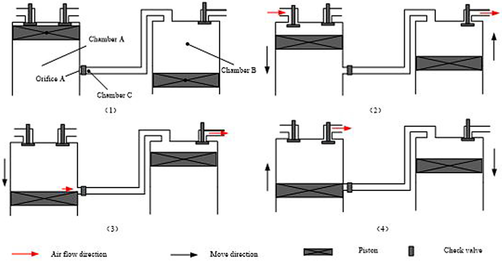
The characteristics of the proposed engine lie in the following aspects: in first expansion process, the exhaust system consists of two parts. One is situated on the head of the cylinder which is driven by cam system; the other exhaust port is situated near the position of BDC. When the piston A runs down to near the position of orifice A, the air with residual pressure in chamber A enters into chamber C and chamber B through check valve and heat exchanger. The compressed air in chamber B from chamber A continues to push the piston B downward.
The working process of the proposed engine is divided into four parts: the intake stroke, the one-stage expansion stroke, the two-stage expansion stroke and the exhaust stroke.
In the intake stroke, the air flows into one-stage cylinder through one-stage intake valve, pushes the one-stage piston downward and produces output work. In the meantime, the air inside two-stage cylinder exhausts under the impetus of the two-stage piston through the two-stage exhaust valve.
The one-stage expansion stroke begins when the one-stage intake valve closes after a specific angle. The air inside one-stage cylinder expands to push the one-stage piston down and output work. Meanwhile, the air inside two-stage cylinder is discharged through the two-stage exhaust valve.
The two-stage expansion stroke process begins when the one-stage piston downward and the upper face of one-stage piston A arrives the orifice port C. The working gas with certain pressure which flows into two-stage cylinder through check valve pushes the two-stage piston downward and output work. The two-stage expansion stroke finishes when the one-stage piston upward and the upper face of one-stage piston A arrives the orifice port C.
In the exhaust stroke, the one-stage exhaust valve opens so that the air with residual pressure exhausts under the impetus of the one-stage piston which is pulled upward by the crank and connecting rod mechanism. After the one-stage piston moves back to the top dead center (TDC), the two-stage expansion air engine completes a work cycle.
From the above description the principles, the proposed two-stage expansion air engine can make fully use of the energy of the high-pressure. Compared with the single-cylinder expansion air engine, the two-stage expansion air engine produces higher power output and higher energy efficiency.
To ensure the two-stage piston type expansion air engine running in the form of above working process, the open and close duration, angle of the intake and exhaust valves is important. Based on above description, distribution phase of the air-power engine must meet the following requirement. When the upper face of one-stage piston reaches to the position C, the two-stage piston is near the TDC. The position relationship between one-stage piston and two-stage piston can be description by Figure 3.

Schematic diagram of the position of two pistons.
From the piston-crank geometry, if the piston pin offset is ignored, the one-stage piston displacement is given by 18

where, r1 is the one-stage crank radius, L1 is the one-stage connecting rod length, β1 is the angle of the one-stage connecting rod and θ1 is the one-stage crankshaft angular position.
The relationship between β1 and θ1 is given by

Simultaneously, the two-stage piston displacement is

where
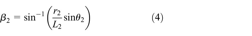
where, r2 is the two-stage crank radius, L2 is the two-stage connecting rod length, β2 is the angle of the two-stage connecting rod and θ2 is the two-stage crankshaft angular position.
According the working process of the two-stage piston type air engine, the relationship between the one-stage crankshaft angular position and the two-stage crankshaft angular position is expressed by

where θi is the initial phase difference of two crankshaft.
Based on the boundary conditions, y1 = yc and y2 = 0, the initial phase difference of the two crankshaft, the initial phase difference of two crankshaft, θi, can be expressed as
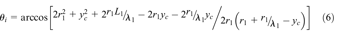
where

where yc is the distance between the TDC of cylinder A and the upper of the orifice A which is expressed by

where λc1 is the ratio between yc and r1.
Thermodynamic models
A thermodynamic model of the two-stage piston type air engine is developed by using the thermodynamic models of the expansion air engine. 19 The following assumptions are made. First, the high pressure air was supplied at a fixed pressure and temperature. Second, the air is ideal which means specific heat u and specific enthalpy h are only related to the temperature. Third, in working process, the air engine has no heat exchange with the external environment. Fourth, the state of air is not influenced by the check valve. Finally, the influences of flow resistance, leakage and friction are ignored.
To model a piston-type air-powered engine, Chi-Min Liu et al. 20 and Qiyue Xu et al. 21 have been given some methods. The thermodynamic model is used to characterize the expansion air engine with such state variables as volume, mass, temperature and pressure.
The volume
The volumes of the one-stage cylinder and the two-stage cylinder are variable due to the movement of the piston


where V1 and V2 are the volumes of the one-stage cylinder and the two-stage cylinder, respectively, y1 and y2 are the pistons position, respectively, which are denoted by the crankshaft angular position, D1 and D2 are the diameter of the pistons, respectively.
The mass
The high pressure gas flows into the cylinder through the intake valve. The mass flow rate is calculated by the critical pressure ratio which is given by

where


where, G is the air mass flow (kg/s), Ae is effective area of intake and exhaust port (m2) which is calculated based on driving cam profile, p is the pressure (Pa), R is gas constant which is equal to 287 J/(kg.K), κ is specific heat ratio which is equal to 1.4, T is the air temperature(K), the subscripts u and p represent the upstream side and downstream side, respectively.
The circulation area of intake and exhaust port is described by
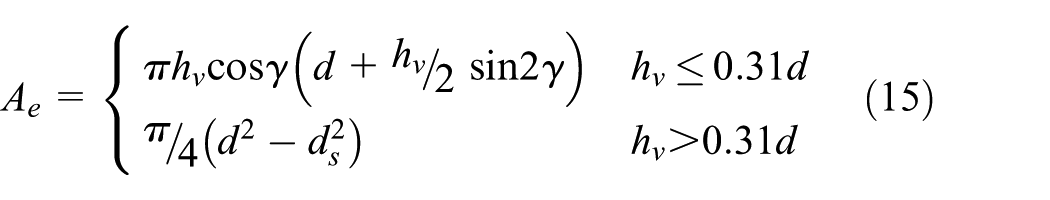
where hv is the valve lift (m), γ is the cone angle of the valve sealing (rad), d is the diameter of the flow passage (m) and ds is the diameter of the valve steam.
The valve lift is determined by the cam profile. The relationship between valve lift and crank angle is shown in Figure 4.

The curve of the valve lift.
Figure 5 shows the schematic diagram of the effective area of orifice A. The effective area of orifice port is described by.


Schematic diagram of the effective area of orifice.
where Ll is the length of the orifice, Lw is the distance of between the upper orifice A and the BDC.
According to mass conservation, the mass inside cylinder can be described by
where the subscripts in and out, respectively, indicate the in and out cylinder.
The pressure
The pressure variation in the air in cylinder can be obtained by driving the state equation of ideal gases

The energy
The temperature difference can be obtained by solving the energy equation. For a thermodynamic system, the increase in internal energy equals to the sum of the heat, the change of enthalpy and the work. Accordingly, the energy balance is described by

For simplicity, both the processes of expansion and compression are considered as isentropic process, the gas in cylinder has no heat exchange with the atmosphere. Therefore, the energy balance of the cylinder is written by

where hin and hout are the specific enthalpies of the air flow in and out of the cylinder, respectively, min and mout are the mass of the air flow in and out, respectively, W is the work, Cv is the constant volume specific heat.
The efficiency
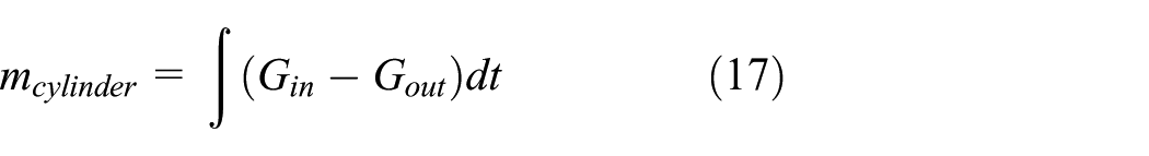
For one cycle, the work done by the engine is

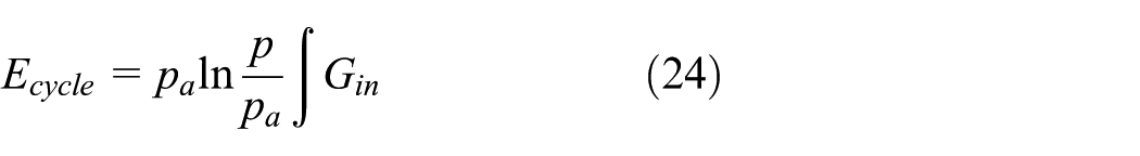
According to the literatures,22,23 available energy of flowing compressed air can be given by

where Va is the volume of air at the standard state, pa is the pressure of atmosphere and Ta is the temperature of atmosphere. If the temperature of air is equal to that of atmosphere, the equation (20) can be written by

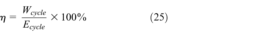
Therefore, for one cycle, the consumed energy is
Accordingly, the efficiency is
Analysis and discussion
Single stage CAE vs two-stage air CAE
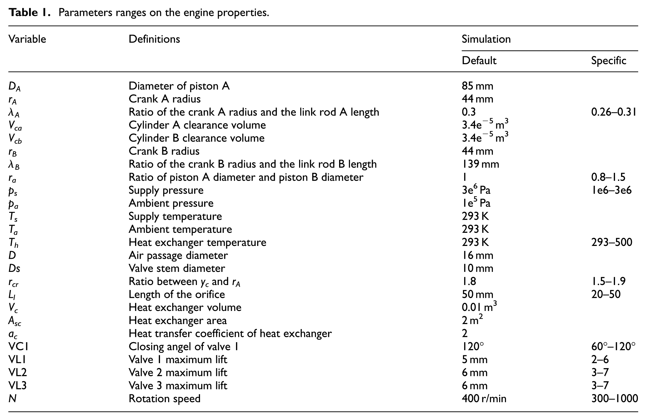
The pressure and temperature in environment is set to 0.1013 MPa and 293 K. The rest data is provided in Table 1. The intake pressure is regulated to the working pressure of the engine. Figures 5 and 6 provide the efficiency and power comparison of the two kinds of expansion air engine at different supply pressures.
Parameters ranges on the engine properties.
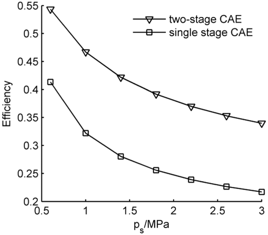
The efficiency comparison: pressure 0.6–3 MPa.
Figure 6 shows the efficiency comparison of the two-stage CAE and single cylinder CAE at different supply pressures. The two engines could be operated at 3 MPa owing to apply pressure-compensated valve mechanism which details are described by reference. 13 The efficiency decreases with the supply pressure increasing. And the efficiency of the two-stage CAE is higher than single stage CAE at same supply pressure. When supply pressure is set at 0.6–3 MPa, the efficiency of two-stage CAE is approximately 1.31–1.56 times of that of single stage CAE.
The mainly reason is that the high supply pressure leads the increasing of exhaust pressure, and then the energy in compressed air is wasted. The two-stage expansion mechanism improves the expansion ratio, so its exhaust pressure is significantly reduced.
Figure 7 shows the power comparison of the two-stage CAE and single stage CAE at different supply pressures. The power increases with the supply pressure increasing. And the output power of the two stages CAE is higher than single stage CAE at same supply pressure. When supply pressure is set at 0.6–3 MPa, the power of two-stage CAE is approximately 1.31–1.56 times of that of single stage CAE.

The power comparison: pressure 0.6–3 MPa.
The primary reason is that the output power is proportional to the supply pressure.
Figures 8 and 9 show the efficiency and power comparison of the two engines at different rotation speed.

The efficiency comparison: rotation speed 300–1000 r/min.

The power comparison: rotation speed 300–1000 r/min.
Figure 8 shows the efficiency comparison of the two stages CAE and single cylinder CAE at different rotation speed. The supply pressure is set at 3 MPa. The efficiency decreases with the rotation speed increasing. And the efficiency of the two-stage CAE is higher than single-stage CAE. When rotation speed is 300–1000 r/min, the efficiency of two-stage is about 1.4–3 times of that of single stage CAE.
With respect to the single cylinder CAE, the air inside cylinder cannot discharge in time in high rotation speed during the exhaust stroke and then cylinder pressure increases with the rotation speed increasing. Nevertheless, with respect to the two stages CAE, a part of air with residual pressure flows into two-stage cylinder and output work, thus the efficiency of the two stages CAE is higher than single stage CAE in same rotation speed.
Figure 9 shows the output power comparison of the two-stage CAE and single-stage CAE at different rotation speed. The power increases with the rotation speed increasing. And the output power of the two stages CAE is higher than single stage CAE at same rotation speed. When the rotation speed is 300–1000 r/min, the power of two-stage CAE is approximately 1.4–3.2 times of that of single stage CAE.
Air distribution system
Air distribution system has great influence on the efficiency and output power of the CAE. According to the working process of a two-stage piston type CAE, the following variables for air distribution can be changed: the closing angle of valve 1(VC1), the lift of valve 1 (VL1), the lift of valve 2 (VL2), the lift of valve 3 (VL3). The initial simulation parameters are shown in Table 1. The Figure 9 depicts the output power and efficiency characteristics of the proposed CAE.
The following results can be obtained from Figure 10.

Output power and efficiency characteristics of the proposed CAE. (a) VC1 vs output power and efficiency, (b) VL1 vs output power and efficiency, (c) VL2 vs output power and efficiency, and (d) VL3 vs output power and efficiency.
The output power increases rapidly with an increase in the closing angle of valve 1, and the efficiency declines rapidly with an increase in the closing angle of valve 1.
The primary reason is that the increasing VC1 causes a large growth in consumption of the compressed air which raises the average pressure in cylinder and then improves the output power. However, the energy of compressed air which flows into the cylinder is not utilized fully.
2. The output power ascends slowly with increase in the lift of valve 1, the lift of valve 2 and the lift of valve 3. The efficiency declines slowly with an increase in the lift of valve 1, and the efficiency ascends slowly with an increase in the lift of valve 2, the lift of valve 3.
The main reason is that, the compressed air flowing into cylinder is not be made fully use of. The increasing lift of valve 2 and valve 3 can reduce the resistance of the exhaust, so the efficiency increases.
The cylinder diameter ratio
The cylinder diameter ratio is defined to the ratio of piston A diameter and piston B diameter. It is important to the two-stage CAE. The output power comes from the product of a pressure and an area of piston. Figure 11 provides the relationship between the cylinder diameter ratio and the output power, efficiency.
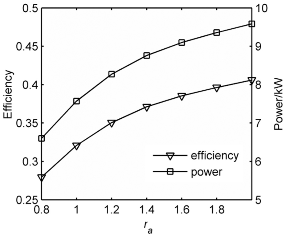
Influence of ra on the efficiency and power.
Figure 11 gives that the output power and efficiency ascend rapidly with an increase in the cylinder diameter ratio. On one hand, the compressed air which comes from one stage expansion flows into cylinder B, the bigger the diameter of piston B, the higher the output power. On the other hand, the bigger cylinder diameter ratio causes the bigger ratio of expansion in cylinder B, which causes the energy in compressed air to be fully used.
The orifice port shape
The orifice port shape is determined by the ratio between the distance of the upper part of the orifice and the TDC and the radius of the crank, and the length of the orifice. The mass flow rate flowing into cylinder B is determined by the orifice port shape, so the orifice port shape influences the output power and efficiency of the two-stage CAE. The influence of rcr on the efficiency and power is shown in Figure 12. The influence of Ll on the efficiency and power are shown in Figure 13.

Influence of rcr on the efficiency and power.

Influence of Ll on the efficiency and power.
From Figure 12, we can see, at the beginning, the output power and efficiency ascend slowly with increase in the distance of the upper part of the orifice and TDC and the radius of the crank, when the value of the rcr is equal to 1.7, the output power and efficiency reach to the highest value. That is because, when the value of rcr is greater than 1.7, the sectional area of the orifice port diminishes which leads to restriction loss, and the when the value of rcr is lower than 1.7, the energy is not utilized fully.
From Figure 13, at the beginning, the output power and efficiency ascend slowly with increase in the length of the orifice, when the length of the orifice is larger than 30 mm, the output power and efficiency remain almost constant. The primary reason is that the mass flow rate almost does not change when the length of the orifice is larger than 30 mm.
Conclusion
To improve CAE output power and energy efficiency, a new kind of two-stage piston type CAE is proposed. Compared with single-stage CAE, the efficiency and output power of two-stage CAE is approximately 1.31–1.56 times of that of single-stage CAE.
The seven factors related to the output power and efficiency of the proposed engine are discussed, and some conclusions are made as follows.
Compared with other air distribution system parameters, the output power and efficiency are mainly determined by the closing angle of valve 1. And the opposite trends of the output power and the efficiency at different closing angle of valve 1.
To the proposed CAE, the bigger the cylinder diameter ratio, the higher the output power and efficiency are.
The output power and the efficiency can reach to the highest value in suitable orifice port shape.
Based on the theoretical analysis, we provide a method to improve the output power and efficiency of the CAE by exploiting the expansion energy.
Footnotes
Handling Editor: Davood Younesian
Declaration of conflicting interests
The author(s) declared no potential conflicts of interest with respect to the research, authorship, and/or publication of this article.
Funding
The author(s) disclosed receipt of the following financial support for the research, authorship, and/or publication of this article: The research work presented in this paper is financially supported by the science and technology innovation Financial Grant (2017CXYD-2) from the Finance department of Inner Mongolia and research fund (2017QDL-B07) from Inner Mongolia University of Science & Technology.