
Abstract
A hydraulic composite actuator is developed for vibration simulation. The hydraulic scheme and control principle are introduced and an open–closed-loop iterative learning control method is proposed for control issue. A special composite cylinder controlled by servo valve and proportional relief valve is designed to generate static force with large amplitude and dynamic force with small amplitude but high frequency. The control subsystem for dynamic force is a zero-type system with very high open-loop gain and uncertainty of parameters; therefore, an open–closed-loop proportional–derivative-type iterative learning control scheme is designed to solve this challenging control issue. A principle prototype of this hydraulic has been developed, and the experiments have been designed for this actuator. Different control methods are experimented for verification and comparison, and experiment results have verified practical applicability of this actuator and the superiority of control scheme.
Keywords
Introduction
Vibration simulation has been applied in the fields of the aspects of aeronautics, astronautics, national defense, and so on. 1 Now the vibration simulation is an important means for increasing the reliability of the products. By simulating the particular vibration environment that products will exposed to in use, transform, and storage, the weakness of design can be early found and the information for correcting design can be obtained in time. 2
The vibration simulation is normally produced by hydraulic actuator (cylinder or motor) or electric motor to generate different kinds of vibration forces. 3 Compared with other types of drives, hydraulic drive has many distinct advantages, such as high power mass ratio and stiffness, fast response, high control precision, compactness, and high payload capability. 4 With the increasing demand for vibration test, the vibration actuators with higher vibration power and control performance are demandingly required. Therefore, hydraulic drive, especially electro-hydraulic drive, has been widely applied in the vibration simulation. 5
Many famous abroad companies, such as American MTS Corporation and Japanese Mitsubishi Corporation, hold a great deal of patent techniques and different kinds of hydraulic vibration control products, 6 but they mainly concentrate on commercial profit, therefore keep the core techniques as secrets, which constrains the progressing pace of hydraulic vibration control. The domestic applications on hydraulic vibration control technology still require innovative research. The vibrating device is generally a conventional servo valve controlled cylinder system, in which the stability and convergence speed of control methods need continuing research, and the control accuracy requires further improvement. 7
A lot of vibration simulation applications request exerting a constant static force to object firstly and then overlaying a high-frequency dynamic force. 8 Conventional hydraulic vibration actuator universally adopts a set of valve controlled cylinder conducting above applications, and the static force and the dynamic force are produced by the same hydraulic cylinder. When the amplitude of static force differs from the one of dynamic force, ideal vibrating effect with high accuracy and vibration frequency is difficult to acquire for the conventional hydraulic vibration. Furthermore, more energy will be wasted when vibrating experiment lasts a long time; therefore, the large amount of heat converted by the wasted energy can easily aggravate the wear and tear of the piston rod and the seal in the cylinder. 9
The electro-hydraulic control system is highly nonlinear, which may be subjected to friction, dead zone, fluid compressibility, dead-band, internal leakage, and hysteresis; 10 furthermore, the dynamic performance of control valve is often influenced by supply pressure, fluid and ambient temperature, and so on. Apart from the nonlinear nature of hydraulic dynamics, the electro-hydraulic control system also has a large extent of model uncertainties, which cannot be modeled exactly, and the nonlinear functions that describe them accurately may not be known. 9 The hydraulic control system for vibration simulation has the characteristics of parameter uncertainty, nonlinearity, asymmetry, and time-variation; therefore, control for such system is a more challenging issue.
Conventional proportional–integral–derivative (PID) control has been widely used in hydraulic system for its simplicity, clear functionality, and easy implementation, 11 but it is difficult to achieve satisfactory control performance because of the above nonlinear and uncertain factors. Therefore, current research is focused on nonlinear control methods, designed to change control parameters adaptively in real time so as to achieve the desired performance. In recent years, iterative learning control (ILC) has gained considerable interest from researchers. In general, ILC uses information from previous executions in the iterative process of finding the learned commands so as to improve performance under repetitive motion. 12 Some applications of ILC in electro-hydraulic system have proved its effectiveness. Considering the repetition of movement in the vibration simulation, ILC is expected to provide a feasible solution for control issue.
In this article, a hydraulic composite actuator is developed for vibration simulation. A special composite cylinder controlled by servo valve and proportional relief valve is designed to generate static and dynamic tensional force, and the open–closed-loop ILC method is proposed to achieve high-precision control performance for this vibration actuator. The rest of the paper is organized as follows. Section “Principle of the composite actuator” introduces the principle of the composite actuator, including hydraulic and control principles. Section “Design of the composite cylinder” presents the special design of the composite cylinder. In section “Model analysis of the composite actuator,” the model of the composite actuator is derived, and its characteristics are also analyzed. In section “Controller design for composite actuator,” an open–closed-loop PD-type ILC method is designed for this actuator. In section “Experiment,” the physical composite actuator is described, and the experimental results are also presented. Finally, conclusions are given to summarize the main points of this article.
Principle of the composite actuator
Hydraulic principle of the composite actuator is illustrated by Figure 1, including a special composite cylinder and corresponding hydraulic control circuits. According to control object, the hydraulic circuits can be divided into two parts, circuit for dynamic force and circuit for static force.

Hydraulic principle for the composite actuator.
The composite cylinder is the most important and special device in the actuator, whose purpose is to generate the vibration force. Because of complexity of the vibration force, which is simplified to the combination of large static force and small dynamic force in this article, it is difficult for the conventional electro-hydraulic system based on servo valve controlled cylinder to generate such kind of force with high precision. Compared with common asymmetrical or symmetrical cylinder with two chambers and one rod, this composite cylinder is designed to have a special compound structure, combined by a large static cylinder and a small dynamic cylinder, to generate the vibration force composed of static and dynamic forces. The special structure of this composite cylinder is introduced in section “Design of the composite cylinder.”
As shown in Figure 1, the static cylinder with large piston area can generate a static force with large amplitude, while the dynamic cylinder with small piston area can generate a dynamic force with small amplitude and high frequency. Both of their pistons share the same rod, which completes transmission and combination of the static and dynamic forces. A force sensor is mounted between the piston rod and the tested object to measure the vibration force, and a displacement sensor installed in the rod’s interior is to measure the deformation of the tested object in vibration test.
To control this composite cylinder with four chambers and one rod, two sets of hydraulic circuit are applied, the proportional hydraulic circuit for the static force and the servo hydraulic circuit for dynamic force. The proportional hydraulic circuit, including the solenoid directional valve, the proportional relief valve, and hydraulic power, is to control the static cylinder. The proportional relief valve regulates the working pressure of the static cylinder to control the amount of the static force. The 4/3-way solenoid directional valve decides the moving direction of the rod, when in left position, the rod extends to connect with tested object; when in right position, the rod retracts to pull tested insulator; when in neutral position, the position and output force of the pod are locked.
The servo hydraulic circuit is made up of the electro-magnetic ball valve, the servo valve, the accumulator, and corresponding hydraulic power. The dynamic cylinder is controlled by the servo valve to generate the dynamic force with small amplitude and high frequency. The electro-magnetic ball valve working between two ports of the dynamic cylinder is to control the working status of the servo hydraulic circuit: the circuit is enabled to work when the ball valve with electricity, while the circuit fails to work when the ball valve without electricity, because two ports of the dynamic cylinder are connected and then the output force can be considered to be zero. The purpose of accumulator is to provide instantaneous flow for the dynamic cylinder and keep the working pressure of servo valve stable, which helps to improve the dynamic performance of the composite actuator.
Design of the composite cylinder
Being the most important and special device in the actuator, the composite cylinder is designed to generate the vibration force. As shown in Figure 2, the structure of this cylinder is different from the one of traditional cylinder with one rode and two chambers, including the static cylinder, the dynamic cylinder, the piston rod, and the cooling mechanism.
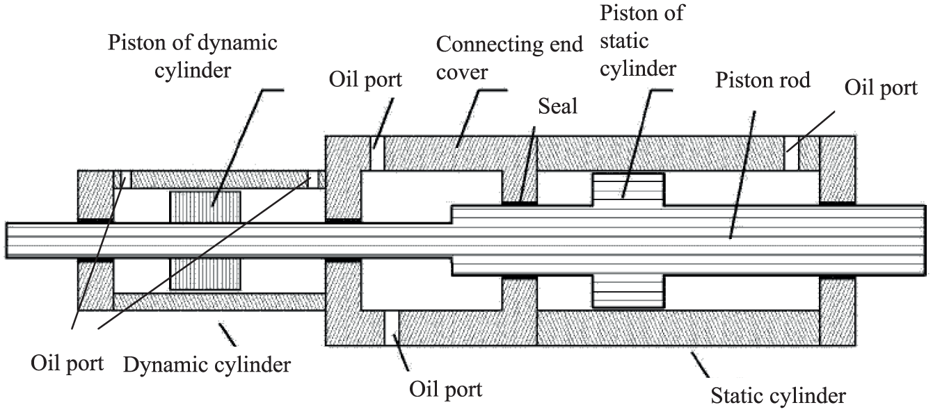
Structure of the composite cylinder.
The static cylinder is injected pressure oil with given value to generate static force with fix value and large amplitude, while the oil pressures of two chambers in the dynamic cylinder are controlled by the servo valve to generate dynamic vibration force with small value and high frequency. When the static force produced by the static cylinder reaches the setting value, the oil ports of the static cylinder can be closed to keep the pressures in two chambers fixed; therefore, even if the hydraulic power is not provided, the static force still remains unchanged; as a result, the purpose of energy saving and heat reducing could be reached by this means.
Connected by a connecting end cover, the static cylinder and the dynamic cylinder use the same piston rod, whose two terminals stretch out from the end covers of two cylinders separately, using for connecting tested objects. The piston rod is a kind of step beams with multi-diameter and double pistons; the thick section with large diameter and piston is located in the static cylinder, while the thin section with small diameter and piston is located in the dynamic cylinder. Between two cylinders, the connecting end cover with two different size piston holes is to connect and fix two cylinders, which the stepped section of the rod is inside.
During durable vibration test, a lot of friction heat is accumulated in the composite cylinder, which could be a great threaten to stability and reliability of the actuator. Therefore, a double cooling mechanism is designed to solve the heat problem, including the cooling mechanisms for the piston rod and the cylinder. Double cooling mechanism of the composite cylinder is shown in Figure 3.

Double cooling mechanism of the composite cylinder.
The cooling mechanism for the piston is located in the static piston rod. As shown in Figure 3, the guide pipe with stainless steel material is installed in the hollow structure of the static piston rod section. At the end of the guide pipe, port A is the entrance of the coolant, while port B in the side wall of the piston rod is the outlet. The coolant goes through the guide pipe from port A to port B, which can take away the heat in the piston rod.
The cooling mechanism for the cylinder is located in the static cylinder. There are some oil holes in two end covers of the static cylinder, and some oil channels are designed in the side wall of the static cylinder to connect these holes, which forms the circuit for the coolant. Therefore, the coolant can go through these oil holes and channels to take away the heat in the cylinder.
This special structure of the composite cylinder not only realizes high accuracy vibrating control for the composite actuator, but also has the advantages of energy saving and high reliability. The two chambers of the static cylinder could stop oil-supply in the durable vibration test, resulting in saving energy and reducing calorific value. At the same time, the double cooling mechanisms in the static cylinder can significantly decrease heat quantity produced by friction, especially adapting to long-time high frequent vibrating experiments.
Model analysis of the composite actuator
The subsystem for dynamic force in the composite actuator is a typical force servo system containing a symmetric servo cylinder (dynamic cylinder) and a two-stage servo valve in dual nozzle flapper. After some simplification, the model block of this subsystem can be described by Figure 4, where U is the input for the control command, F is the output of the loading force, X is the load displacement,
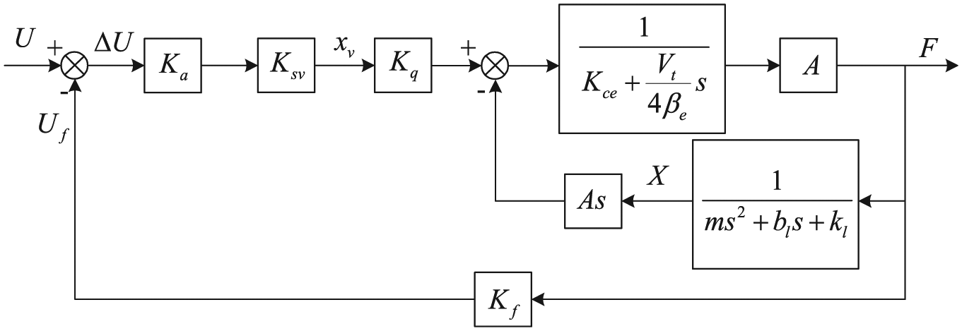
The block diagram of the electro-hydraulic servo force control system.
The open-loop transfer function of the force control system is shown by equation (1)

Then it can be simplified to equation (2)

where
From the open-loop transfer function in equation (1), it can be found that the subsystem for dynamic force is a 0-type system, which is different from the model of conventional hydraulic position control system and is easy to become unstable.
13
At the same time, the open-loop gain
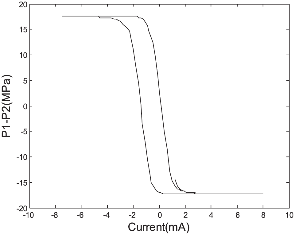
Current–pressure curve of the servo valve.
The characteristic of the proportional relief valve has been analyzed and described by means of methods of classical control theory, but the derived model is complicated, which causes inconvenience to system analysis and simulation. Therefore, in present study, the model of the proportional relief valve is simplified to a second-order oscillation system with time-delay element,
14
as shown by equation (3), where

Due to bad dynamic characteristics of the proportional relief valve, as well as its server nonlinearity, 14 the traditional PID control is applied for the static force control subsystem, to complete stable and rough control for the static force.
Controller design for composite actuator
ILC adopts the strategy of learning in repetition, with the abilities of memory and correction; thus, it is suitable for nonlinear, time-variable, and model-free systems and can absolutely trace a desired trajectory during limited periods by simple arithmetic calculations. 15 ILC is also a low-complexity and robust controller for identification, model reduction, and controller reduction of higher order systems, which can meet real-time control requirement of motion control systems. 12 Therefore, ILC has provided a feasible solution for the control issues of vibration simulation.
Given
According to the usage of error information, ILC algorithm can be divided into open-loop ILC, closed-loop ILC, and open–closed-loop ILC.
16
An open–closed-loop ILC is designed in this application, which can be considered as a combination of open-loop and closed-loop ILCs, drawing on both present and former iteration information at the same time to get updated control signal.
17
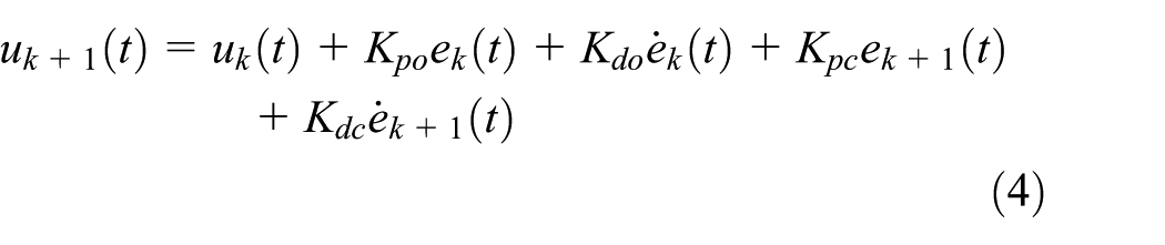
In open–closed-loop ILC, PD-type learning law is adopted, expressed by equation (4), where
The update control value
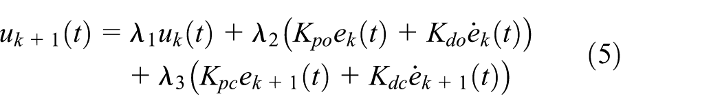
Different control forms can be obtained from equation (5) by flexible settings of
The controller scheme based on open–closed-loop PD-type ILC is described in Figure 6, and the working procedure can be described as follows. First,


Scheme of controller based on open–closed-loop PD-type ILC.
Experiment
Principle prototype
Based on the hydraulic and control principles discussed above, the principle prototype of the composite actuator has been developed. As shown in Figure 7, the actuator is composed of a dynamic cylinder, a static cylinder, a servo valve, a proportional relief valve, a magnetic ball valve, and the accumulator. The specifications of main component in the composite actuator are listed in Table 1.

The principle prototype of the composite actuator.
List of main components in the compound actuator.

The computer control and test system for the actuator is made up of an embedded controller and a testing computer, forming an upper-lower distributed computer structure. The embedded controller completes the bottom closed-loop force control, whose hardware consists of a 486-level 100 MHz embedded CPU board with PC104 bus, signal amplifier, 16-bit analogue to digital and 16-bit digital to analogue converters, and ILC control algorithm is carried out on this controller, with operation cycle less than 0.2 ms. The testing computer, an industrial control computer, is used to set force regularity, sample the data, record running time, display test curves, analyze vibration performance, and communicate with embedded controllers by Ethernet network and User Datagram Protocol (UDP) protocol.
A set of pump station is used to provide hydraulic flow to the actuator, with maximum pressure of 31.5 MPa and maximum flow of 80 L/min. In order to control oil temperature for a long operating duration, a set of water cooling system is also applied in the hydraulic pump station.
Experimental results
In this section, a composite insulator with model FXBW-500/300 is tested by this actuator. The first ramp stage is for static force with maximum of
The experiment for the vibration force is developed by this actuator, and different control methods are experimented for further verification and comparison, and experiment results have verified practical applicability of this actuator. Figure 8 gives the force curves of open–closed-loop PD-type ILC and PID, respectively, at vibrating frequencies of 40 and 100 Hz, where
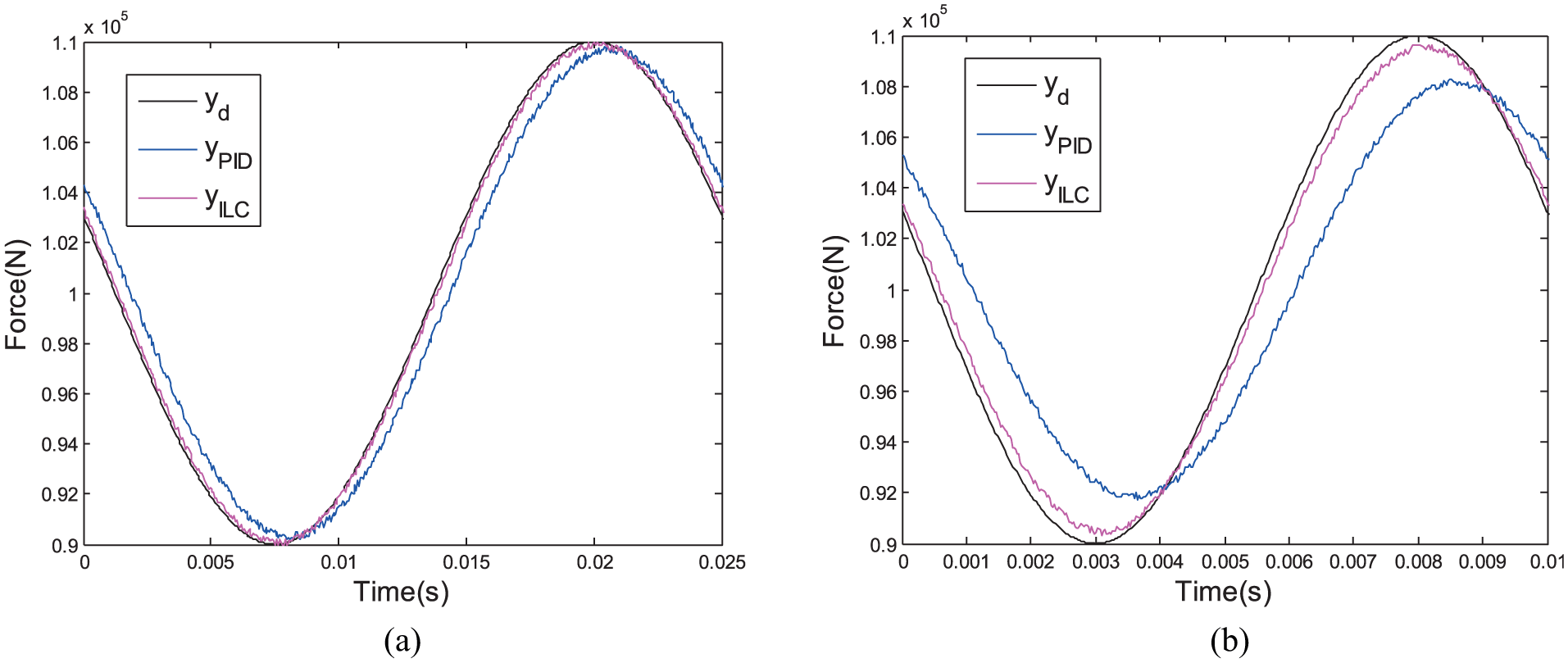
Force curves of open–closed-loop PD-type ILC and PID under vibrating frequencies of (a) 40 Hz and (b) 100 Hz.
In actual applications, amplitude error is a very important index for the fatigue testing machine, which is defined as the difference between amplitudes of desired and actual output curves. When the vibrating frequency changes from 20 to 100 Hz, the amplitude errors of PID control and open–closed-loop PD-type ILC,
Amplitude errors of PID and open–closed-loop PD-type ILC at a serial of different vibrating frequencies.

PID: proportional–integral–derivative; PD: proportional–derivative; ILC: iterative learning control.
The experiment data indicate that in the low-frequency vibration period (below 60 Hz), both ILC and PID control are able to achieve ideal effects, and the former is slightly better than the latter numerically, but with the increase of the vibration frequency, the amplitude error of ILC is much smaller than that of PID control obviously. At high vibrating frequencies, amplitude error of PID control becomes larger notably, reaching to 2 kN at 100 Hz. Although the error of ILC also increases, it is still far less than that of PID control, with only 0.5 kN amplitude error at 100 Hz.
For comparison of actual convergence speed, closed-loop and open-loop ILCs are also applied in actual insulator test, and Table 3 shows amplitude errors of open–closed-loop, closed-loop, and open-loop ILCs, where
Amplitude errors of open–closed-loop, closed-loop, and open-loop ILCs.

ILC: iterative learning control.
Conclusion
In this article, a hydraulic composite actuator is developed for vibration simulation. The hydraulic scheme and control principle are introduced and an open–closed-loop ILC method is proposed for control issue.
A special composite cylinder controlled by servo valve and proportional relief valve is designed to generate static force with large amplitude and dynamic force with small amplitude but high frequency. The control subsystem for dynamic tensional force is a zero-type system with very high open-loop gain and uncertainty of parameters; therefore, an open–closed-loop PD-type ILC scheme is designed to solve this challenging control issue.
Based on discussed electro-hydraulic control technology, a principle prototype of this actuator has been developed, the experiments have been designed for this actuator, and the results have verified the feasibility of system principle and the superiority of control scheme.
Footnotes
Handling Editor: Ito Kazuhisa
Declaration of conflicting interests
The author(s) declared no potential conflicts of interest with respect to the research, authorship, and/or publication of this article.
Funding
The author(s) received no financial support for the research, authorship, and/or publication of this article.