
Abstract
Laser stripe vision sensors have limited application when the whole surface of an object has to be measured; therefore, a galvanometric laser scanner is presented using a one-mirror galvanometer element as its mechanical device to drive the light stripe to sweep along the object. A flexible plane-constraint together with a look-up table calibration algorithm by viewing a planar calibration target from unknown orientations is presented to calibrate the proposed galvanometric laser scanner. The plane-constraint method generates a larger number of control points by imposing a plane constraint on the control points. Compared with the invariance of double cross-ratio, the plane-constraint-based calibration method generates the same number of control points without error propagation. Contrast experiments are conducted to verify the efficiency and accuracy of the proposed calibration method.
Keywords
Introduction
Laser stripe vision sensors have been gaining wide acceptance in industry inspection due to fast acquisition time, a very simple structure, low cost, and robust nature. The inspection principle of the laser stripe vision sensor is shown in Figure 1. In Figure 1, a laser projector projects a light stripe plane onto the object’s surface, forming a light stripe. The light stripe is modulated by the depth of the object’s surface. Consequently, the distorted light stripe contains three-dimensional (3D) characteristic information of the object’s surface. The 3D characteristic information of the object’s surface can be derived from two-dimensional (2D) distorted light stripe images. However, a laser stripe vision sensor can only obtain the point cloud on one light stripe, so it has limited applications when the whole surface of the object must be measured. 1 Consequently, a galvanometric laser scanner is presented using a one-mirror galvanometer element as its mechanical device to drive the light stripe to sweep along the object to gather the point cloud on all the light stripes. The proposed galvanometric laser scanner consists of two main parts: a laser stripe vision sensor and a galvanometric element. Therefore, calibration of the laser stripe vision sensor is the basis of the proposed laser scanner. There are two ways to complete the laser stripe vision sensor calibration process. One is based on the homography model 2 between the light stripe plane and the image plane, which is called the one-step calibration method, and the other is based on the simple triangular methodology, 1 which is the two-step calibration method. Unfortunately, an effective and highly accurate extraction of calibration points (control points) for a laser stripe vision sensor has been an obstacle to calibration.
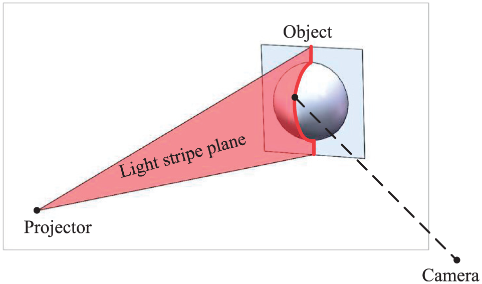
The inspection principle of the laser stripe vision sensor.
Tremendous efforts have been devoted to the field of extracting the control points to calibrate the laser stripe vision sensor, and a wide range of methods have been developed. Xu et al. 3 and Huynh et al. 2 separately present a novel method which is based on the invariance of cross-ratio in the perspective transformation. The novel method is used to get the coordinates of control points with respect to the world coordinate system (WCS). A 3D calibration target is used in both methods, because the one-step calibration method does not calibrate the camera and there are no extrinsic parameters of the camera during the calibration process. The number of the control points is limited for the invariance of the cross-ratio method, and many more control points are essential to enhance calibration accuracy. Wei et al. 4 proposes an approach based on the invariance of double cross-ratio to estimate an arbitrary number of control points on the light stripe plane from at least three known world points with a 3D calibration target. However, accuracy of the control points is limited by error propagation, because the invariance of double cross-ratio uses the invariance of cross-ratio on the light stripe again, and the laser stripe plane is not an ideal plane and the light stripe projected on the calibration targets is not an ideal line. The 3D calibration target is very difficult to manufacture accurately, and it is also very hard to capture a good image by viewing the different planes of the 3D calibration target at once. There are also some methods5,6 where the 3D calibration target is constituted by a 2D calibration target and a movable platform. The calibration process is very inconvenient in operation and time-consuming. Zhou et al. 7 present a flexible approach where the invariance of cross-ratio is employed to generate a large number of control points on the light stripe plane by viewing a planar calibration target from unknown orientation. The number of control points is limited at each location of the planar calibration target; the planar calibration target has to be moved many times to gain a large number of control points. Sun 8 obtains many control points by the homography transformation of calibration target planes and camera image plane. However, the homography transformation of calibration target plane and camera image plane is estimated separately via the Levenberg–Marquardt optimization algorithm, and the estimated homography transformation is less accurate and is not needed when camera calibration is performed. As to the structure and calibration method of the 3D laser scanner, Li et al.9–11 designed a laser scanner by mounting the laser stripe vision sensor to the end-effect of a robot. The accuracy of the laser scanner is limited by the absolute accuracy of the robot. The laser stripe vision sensor can also be fixed to the end of a coordinate measuring machine to form a highly accurate laser scanner; 12 however, the coordinate measuring machine is not suitable to install on the production line. There is another form of laser scanner where the position of the projector with respect to the camera coordinate system (CCS) can be determined by additional reference frames13,14 or physical constraints.15,16 Ren et al.17,18 proposed a linear laser scanner by mounting the laser stripe vision sensor to a linear rail; the linear rail moves the vision sensor to perform linear scanning. The shortcoming of the linear laser scanner is that its relatively large size and heavy load of the linear rail will limit its industrial applications. Li and Xi 19 and Xiao et al. 20 presented a rotational laser scanner by mounting the laser stripe vision sensor to a turntable. This has the same drawbacks as the linear laser scanner. The galvanometric laser scanner using the galvanometric element as its mechanical device can solve the aforementioned drawbacks. The galvanometric element consists of a precision motor and a reflective mirror. The precision motor guarantees the accuracy of the galvanometric laser scanner. The load of the precision motor is the lightweight mirror, and it is much lighter than the aforementioned laser scanners.17–20 The galvanometric element is mounted inside the laser scanner, so the size of the galvanometric laser scanner is relatively smaller. Manakov et al. 21 designed a two-mirror galvanometric laser scanner with a point-mark laser projector and proposed a model-driven calibration method. However, the rotational axis that lays on the reflective mirror is assumed in the mathematical model, and initial estimations of the intrinsic and extrinsic parameters of the scanning system are calibrated separately. Wissel et al. 22 presented a data-driven learning method for calibrating the two-mirror galvanometric laser scanner; however, a large amount of data is needed to train the data-driven model. The point-mark laser projector along with the two-mirror galvanometric element spends a lot of time to sweep through the surface of the object, and consequently, the two-mirror galvanometric laser scanner is not suitable for measuring the shape of the object on the production line. Recently, Chi et al. 23 proposed a laser line auto-scanning system for underwater 3D reconstruction; it overcomes the time-consuming drawback of the point-mark laser scanner. 21 However, the mathematical model 23 assumes that the galvanometer rotation axis should completely coincide with the line intersected by the laser plane and the mirror of the galvanometer. The assumption is relatively harsh for machining and assembly accuracy, because the direction of the laser stripe plane is very hard to measure, and consequently, it is impossible to adjust the incoming laser stripe plane to hit the galvanometer rotation axis. In summary, available mathematical models21,23 of the galvanometric laser scanner make some assumptions that require the system to be manufactured and assembled well enough; thus, the available mathematical models are limited in actual applications.
In this article, a galvanometric laser scanner is designed using a one-mirror galvanometric element as its mechanical device. A flexible method is proposed to generate an arbitrary number of control points based on plane constraint by viewing a planar calibration target from multiple orientations. Due to the high repeatability of the galvanometric element, the pre-defined set of light stripe planes in the calibration process can be used in the measuring process. Combined with the look-up table (LUT), the plane-constraint-based calibration method can be used to calibrate the proposed laser scanner. Compared with the invariance of double cross-ratio, the plane-constraint-based calibration approach extracts the same number of control points without error propagation. The remaining sections are organized as follows. Section “System construction” introduces the construction and inspection principle of the proposed laser scanner; section “Mathematical model of a laser stripe vision sensor” presents the mathematical model of the two-step calibration method for a laser stripe vision sensor. The mathematical model consists of the camera model, the projector model and 3D reconstruction in a two-step calibration method. In section “Plane-constraint-based calibration method through planar calibration target,” a plane-constraint-based calibration method using a planar calibration target is described. It includes camera calibration, extracting control points based on plane constraint, transforming from a local WCS to a global CCS, and projector calibration using an orthogonal regression method. To validate the efficiency and accuracy of the proposed method, contrast experiments are conducted in section “Experiments,” and this article ends with concluding remarks in section “Conclusion.”
System construction
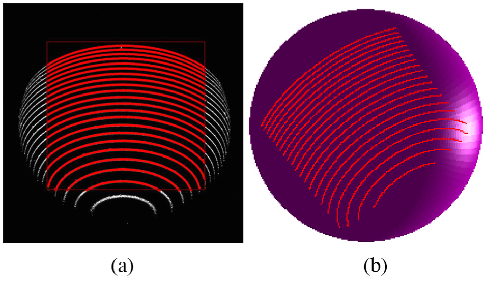
The galvanometric laser scanner is designed using a one-mirror galvanometer element as its mechanical device to drive the light stripe sweep along the object as shown in Figure 2. The galvanometric laser scanner comprised a charge-coupled device (CCD) camera (Basler acA1300/30 µm) with a 16 mm lens, a laser line projector (wavelength of 730 nm, beam width ≤1 mm), and a one-mirror galvanometer element which was made by ourselves using a reflective mirror and a stepper motor (Suruga KRE04360 angular resolution is 0.008°). Here, there are 23 stripe lines in the view of the laser scanner, and each pose of the stripe line is fixed in the CCS owing to the high repeatability of the stepper motor. The LUT method consists of two parts: (1) storing calibration matrices for 23 pre-defined laser planes in an LUT and (2) usage of the calibration matrix at a pre-defined rotational angle for 3D reconstruction. The working principle is as follows: an incoming laser stripe plane, which is projected by a laser line projector, hits the reflective mirror and the light stripe formed by intersecting the outgoing laser stripe plane; the object’s surface is captured by the fixed camera. The 3D characteristic information of the object’s surface can be derived from the 2D distorted light stripe images after 3D reconstruction. The camera is triggered to acquire pictures continuously when the stepper motor gives a hardware trigger signal. The hardware trigger signal is given when the stepper motor rotates across its zero position. The reflected laser stripe plane scans across the object’s surface along with the rotation of the galvanometer element; the 3D information of the object’s whole surface can be reconstructed. The measuring process is shown in Figure 3. In Figure 3(a), the edge points of the circle are extracted in the region(s) of interest (ROI) when the laser line scans across the work piece. Figure 3(b) shows the 3D point cloud of the measured circle after 3D reconstruction.

Schematic diagram of the proposed galvanometric laser scanner.

The measuring process of the work piece feature: (a) the processed gray image and (b) the corresponding 3D point cloud.
Mathematical model of a laser stripe vision sensor
The one-step calibration method is based on the homography model without considering the lens distortion. The proposed calibration method is similar to the two-step calibration method, and consequently, the basic mathematical model in the two-step calibration method for the laser stripe vision sensor is discussed in the following. The two-step calibration method calibrates the camera first and then calibrates the projector since the laser stripe vision sensor is composed of a camera and a projector.
Camera model
The camera has been extensively studied in the past, and its modeling and calibration techniques are very mature.24–27 As shown in Figure 4,

where R and T are the rotation and translation matrices, respectively.

Perspective projection model of camera in the laser stripe vision sensor.
Let

Due to the influences of the radial and tangential lens distortion on
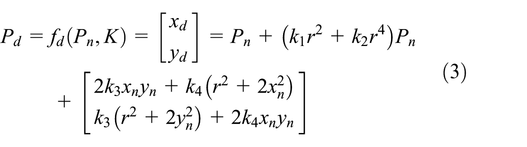
where
The projection point

where
According to equations (1)–(4), the ideal camera model can be written as follows using homogeneous coordinates

where
Equations (3) and (5) show the real perspective projection model of a camera. All parameters in the camera model can be estimated by camera calibration. 26
Projector model
The projector model is accurately represented using the equation of a plane, which is called the light stripe plane. To complete 3D reconstruction, the light stripe plane parameters must be described in the camera coordinate frame. The equation of the light stripe plane is described by

where
The 3D reconstruction
Equations (3), (5), and (6) describe a complete real mathematical model of the laser stripe vision sensor. According to the mathematical model, 3D reconstruction is completed as follows. Here, 3D reconstruction is derived using the intersection of a line and a plane instead of the triangular-based method. Equation (5) is rewritten to describe the transformation from the camera coordinate frame to the normalized image plane frame

where

Equations (7) and (8) are combined as follows

where
Plane-constraint-based calibration method through planar calibration target
A flexible method is proposed to generate an arbitrary number of control points based on plane constraints by viewing a planar calibration target from multiple orientations. It is a very effective method; at least two different poses of the planar calibration target must be viewed by the camera. The plane-constraint-based calibration approach extracts the same number of control points as the invariance of double cross-ratio, but it does not suffer from error propagation. Combined with LUT, the proposed galvanometer laser scanner is calibrated using the plane-constraint-based calibration method.
Camera calibration
Camera calibration is conducted to estimate intrinsic parameters which reflect the optical characteristics of the camera and extrinsic parameters that express the pose of the local WCS relative to the CCS. Zhang 26 presents a flexible camera calibration algorithm in which a planar calibration target is observed by a camera from multiple points of view. The camera is fixed, the planar calibration target is freely moved, and the relative calibration target poses are unknown. After camera calibration, the pose of each calibration target with respect to the CCS is determined.
Transformation from local WCS to CCS
As indicated in Figure 5, any points expressed in the local WCS can be transformed into the global CCS

where

The diagrammatic sketch of transforming the multiple local world coordinate system into the camera coordinate system.
Computing camera coordinates of control points
Without loss of generality, the local WCS is defined as follows: its original point is located at the upper left corner of the planar calibration target, its X axis is along one side of the target, and its Y axis is along the other side. As a result, the Z coordinates of any points located on the planar target is 0

Equation (5) can be expanded as
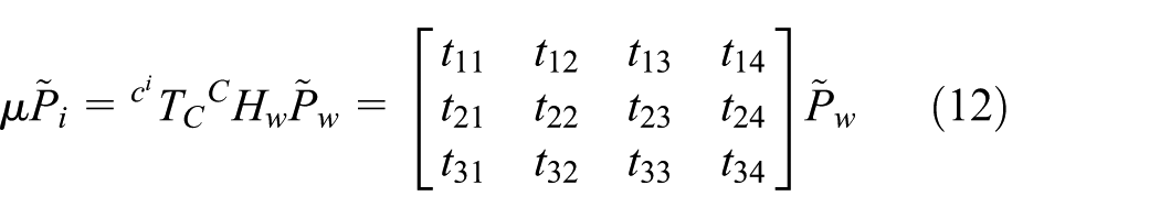
where

where the transformation matrix T is a 4 ×4 invertible matrix, and the fourth row of matrix T indicates that all the world control points are constrained on the OXY plane of the local WCS. The local world control points can be transformed into the global CCS by equation (10). The planar calibration target can be placed in multiple poses, so the proposed method easily extracts a large number of control points.
Projector calibration
A large number of control points
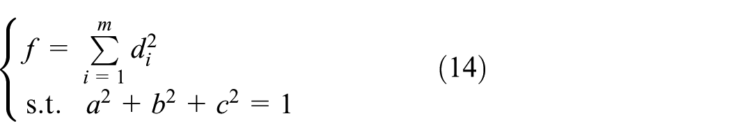
where
A nonlinear least square method is used by Zhou et al. 7 to solve equation (14). The orthogonal regression method is employed to solve the problem. 28 The plane equation can be written as

where
Define

where
The sum of the squares distance from control points to the fitted plane is

Define
and
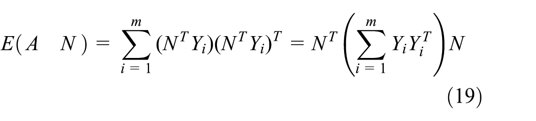
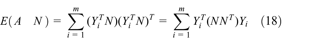
Take the derivative of equation (18) with respect to A to obtain

When
Given A, the symmetric matrix

where U and S are the eigenvectors and the eigenvalues of the matrix
Summary
To sum up, the procedure of the proposed calibration method is described in Figure 6 as follows:
The planar calibration target is located at several different poses, and each pose of the planar calibration target is captured by the camera. The last two poses are captured twice in two cases, one with no laser stripe line projected onto the planar for camera calibration and the other with laser stripe line for projector calibration.
The captured images without laser stripe line are used to calibrate the camera and both intrinsic parameters and extrinsic parameters are determined.
Extract all the image coordinates of the control points in captured images.
Correct the distortion for image coordinates according to equation (3).
Transform the image coordinates of the control points to the local WCS using both camera intrinsic parameters and extrinsic parameters according to equation (13).
Transform the local world coordinate of control points to the global CCS according to equation (10).
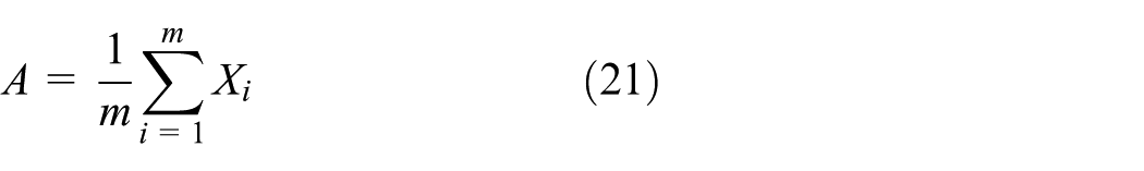
Calibrate the projector according to equations (21) and (22).
Each laser stripe plane is calibrated and an LUT is established to complete the calibration of the proposed galvanometric laser scanner.
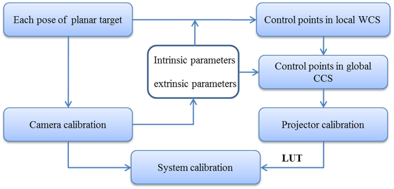
Flowchart of the system calibration procedures.
Experiments
The proposed calibration method is compared with three other calibration methods: the one-step calibration method with the invariance of cross-ratio, 2 the one-step calibration method with the invariance of double cross-ratio, 5 and the two-step method with the invariance of cross-ratio. 7 Four calibration methods use the same calibration images to complete the calibration procedure. Experiments are conducted to verify the efficiency and accuracy of the proposed calibration method.
Calibration procedure
The planar calibration target is located at 20 different poses and the last two poses are captured twice in two cases, one with no laser stripe line projected onto the planar for camera calibration and the other with laser stripe line for projector calibration. There are 20 images for camera calibration and 2 images for each laser stripe plane calibration.
Figure 7 shows the last two images of the planar calibration target in the camera calibration procedure. The coordinate (i, j) in Figure 7 indicates that the center of the circle is located at the ith row and the jth column. The procedure of determining the coordinate is modeled as Single Source Shortest Paths (SSSP) and solved by the Bellman–Ford algorithm. The planar target contains a pattern of 7 ×7 circles. The distance between the adjacent two circles is 3.75 mm in both the horizontal and the vertical directions. Figure 8 shows the four captured images with strip lines lying on the planar target. Figure 8(a) shows the first strip line lying on the 19th pose of the planar target, and Figure 8(b) shows the first strip line lying on the 20th pose of the planar target. Figure 8(c) and (d) shows the 23rd strip line lying on the 19th and 20th pose of the planar target, respectively. Knowing the poses of the last two planar targets, the first and the 23rd laser stripe plane can be calibrated from Figure 8. All 23 laser stripe planes are calibrated and sorted in an LUT for the measuring process.
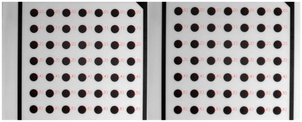
The last two images of the planar target.
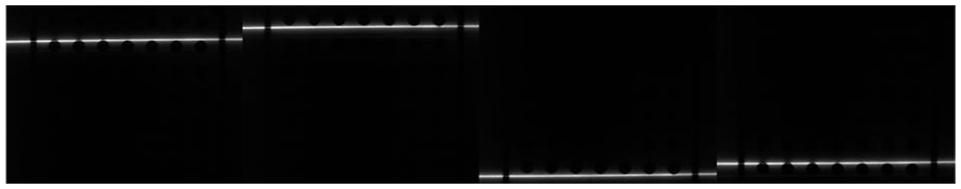
Stripe line lying on the planar calibration target: (a) the first stripe line lying on the 19th planar calibration target; (b) the first stripe line lying on the 20th planar calibration target; (c) the 23rd stripe line lying on the 19th planar calibration target; (d) the 23rd stripe line lying on the 20th planar calibration target.
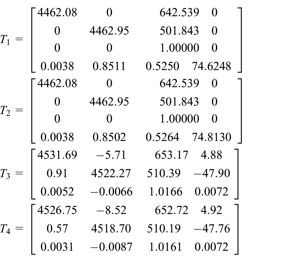
Table 1 shows the calibrated parameters of the proposed method and the other three methods above; only the first laser stripe plane parameters are shown in Table 1. As indicated in Table 1, the proposed method and the Zhou’s method are the two-step calibration methods. The camera parameters are the same for these two methods, while the projector parameters differ. There is a translation (0.2 mm) along the norm vector direction of the plane between the two laser stripe plane equations. However, the rest of the two methods are the one-step calibration method. The homography matrices
Calibration results of the proposed laser scanner.

where
Experiment results
The radius of a standard sphere is measured to verify the efficiency and accuracy of the proposed calibration method. As shown in Figure 9, the designed galvanometer laser scanner is mounted at the end of the robot to construct a robot-based inspecting system. Coordinates of the spherical centers obtained by the laser scanner are used to calibrate the inspecting system. The standard sphere (bearing steel ball and coated with matt material) is measured by the sensor at six different robot positions. The sphere is inspected on a coordinate measuring machine (CMM; Thome, 2 + (L/350) μm) by sampling 15 points evenly on its surface; the standard deviation of distance errors is approximately 12.1 μm, and the diameter is 25.4160 mm. In Figure 10(a), the surface points of the sphere are extracted in the ROI and the corresponding 3D point clouds are obtained after calibrating the laser scanner. Figure 10(b) shows the 3D point cloud and the fitted sphere by nonlinear least-squares sphere fitting algorithm (TLSA). 29 The measurement radius and the root mean square error (RMSE) among four methods are given in Table 2. As indicated in Table 2 and in Figure 11, the RMSE of the one-step calibration method is much larger than the other three two-step calibration methods. This is because the one-step method is based on the homography model, which neglects the lens distortion when the camera is modeled. The RMSE of the plane-constraint-based calibration method is smaller than that of Zhou’s method, because there are only 14 control points to fit each laser stripe plane in the calibration process. The influence of noise contained in the control points will greatly affect the accuracy of the fitted plane when control points are limited in quantity. 4 The 7×7 dot array calibration target should be placed at many positions to extract a large number of control points via Zhou’s calibration method, and it is inconvenient to implement. The plane-constraint-based method theoretically extracts all control points on the calibration target by imposing a plane constraint (Z = 0) on them, so it estimates the laser stripe plane effectively and accurately.

The experimental setup in the automobile production line.
The measuring process of the sphere: (a) the processed gray image and (b) the fitted sphere by TLSA.
The measurement radius among four methods.

RMSE: root mean square error.

The radius error among four methods.
Conclusion
In this article, a galvanometric laser scanner is proposed using a one-mirror galvanometer element as its mechanical device to drive the light stripe to sweep along the object. A flexible plane-constraint-based calibration method together with an LUT calibration method is proposed to calibrate the galvanometric laser scanner. The proposed method only needs the laser scanner to view a planar calibration target located at least two different orientations; orientations of the planar target need not be known, so it is very flexible and easy to implement. Compared with the invariance of double cross-ratio, the plane-constraint-based calibration method generates the same number of control points without error propagation. The experiments conducted in the automobile production line reveal that the proposed approach is more accurate than conventional methods and is effective in the vision inspection system. In addition, the idea of a plane-constraint-based calibration method can be used for reference when other forms of laser stripe vision sensors are calibrated.
Footnotes
Handling Editor: Crinela Pislaru
Declaration of conflicting interests
The author(s) declared no potential conflicts of interest with respect to the research, authorship, and/or publication of this article.
Funding
The author(s) disclosed receipt of the following financial support for the research, authorship, and/or publication of this article: This work is supported by the National Natural Science Foundation of China (nos 51175386 and 51405350).