
Abstract
In order to study the strong force/position coupling problem of passive electro-hydraulic force servo system, taking the valve control swing motor of passive electro-hydraulic force servo system as an object, a new principle of structure coupling is proposed, which based on the analysis of the force/position coupling mechanism and influence factors. The concrete way is to design the load actuator into a compound bilayer structure, which the outer synchronous motor is used to track the bearing motor for position synchronization control, and the inner motor is used to load. Through the load actuator of the compound structure, the passive load is modified into active load, and the problem of force/position coupling is solved fundamentally. The principle of parameter matching, the design of the seal, and the structure of the compound swing motor are given, and the rationality of the oil duct in the inner and outer motors is simulated and tested. Finally, through simulation analysis of passive electro-hydraulic force servo system under small gradient loading, the correctness and effectiveness of structure decoupling are verified. Furthermore, it provides a new approach for the development of passive electro-hydraulic force servo system for ultimate parameter and performance index.
Keywords
Introduction
Passive electro-hydraulic force servo system is often used in the cutting-edge technology field of national defense, such as simulate the aerodynamic hinge torque of ground semi physical missile and other aircraft steering engine. 1 Its characteristics of strong force/position coupling and bearing object uncertainty make it extremely difficult to control. 2
The decoupling method of strong force/position coupling is divided into two broad categories: structural inhibition method and control compensation method. The structural inhibition method includes dual valve control scheme, accumulator calibration, buffer spring calibration, communicating pore buffer calibration, position synchronous compensation, and pressure valve control.3–8 The dual valve control scheme uses the pressure servo valve to load and the flow servo valve compensates the forced flow, and finally, it acts on the same actuating motor; the communicating pore scheme can buffer the forced flow to a certain extent; the pressure valve control is loaded by the strict proportional relation between the output pressure and the control signal. The control compensation method mainly adopts the control algorithm to restrain the coupling torque. Such as multi-variable decoupling control strategy, the whole system is regarded as a multivariable system, in which the decoupling controller is introduced, and the decoupling controller parameters are selected appropriately to restrain the coupling torque.9–12 Based on the principle of structural invariance, the purpose of reducing coupling torque is achieved by feedback of speed signal of loading object.13–15 Based on the compound control strategy, through the combination of different control strategies, the advantages are complementary and have high control precision.16–18
Structural inhibition method is fundamental and control compensation method is auxiliary. Regardless of the control method, it is ultimately loaded by the execution component, and there will always be hysteresis, noise and interference from the input of the control signal to the output of the final execution component. And the traditional local structure inhibition and interference compensation strategy are difficult to achieve the desired simulation results because of the limitations of the loading object and the more stringent simulation indexes as well. Therefore, this article proposes a kind of compound structure swing motor, 19 which turns passive load into active load from the loading principle, and solves the problem of coupling torque fundamentally. It provides a new approach for the development of the passive electro-hydraulic force servo system in the future.
The principle and force/position coupling mechanism of passive electro-hydraulic force servo system
The operational principle diagram of passive electro-hydraulic force servo system is shown in Figure 1. The left side of the figure is the loading system, and the right side is the loading system. The bearing motor drives the loading-motor, and the forced motion of the loading motor lead to the change of the internal flow, and then affects the output torque of the loading motor. In reverse, the output torque of the loading-motor is acts on the bearing system, which results in change of the motion state of the bearing system. So that the motion state of the bearing system and the output torque of the loading system are impacted and interacted each other repeatedly. In order to ensure the loading performance of the loading system, the coupling torque of between must be effectively suppressed.
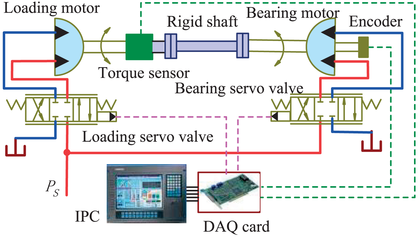
Operational principle diagram of passive electro-hydraulic force servo system.
As shown in Figure 2, the passive electro-hydraulic force servo system model 20 is established by Figure 1.
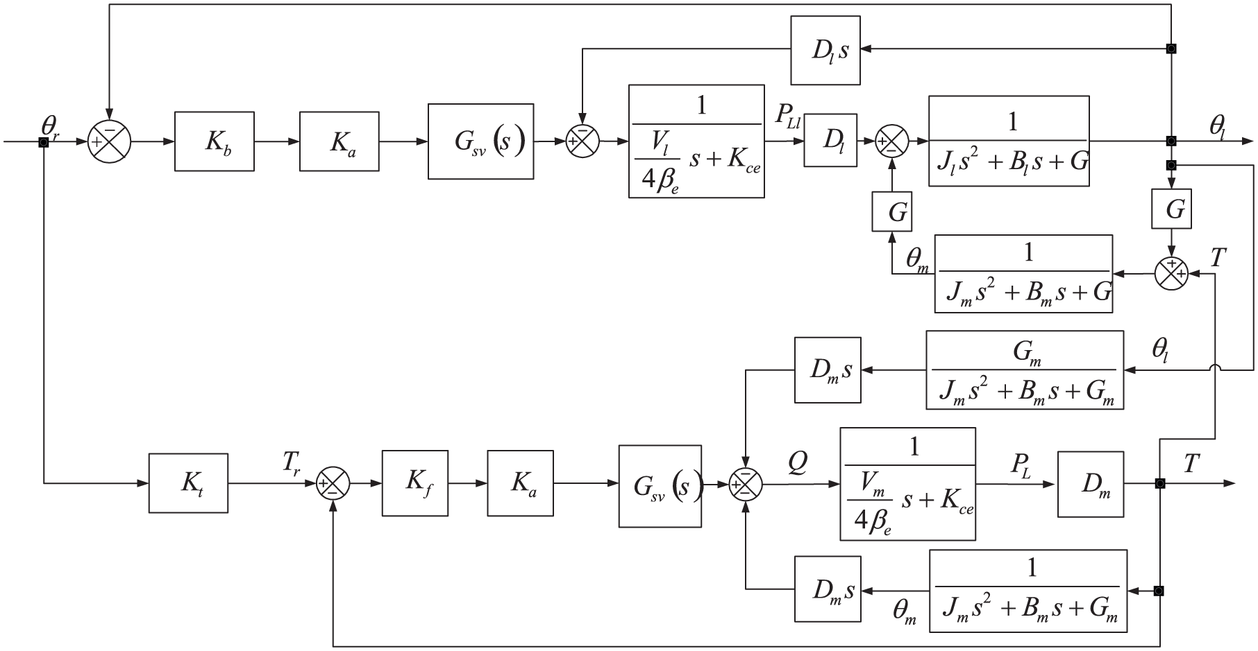
Mathematical model of passive electro-hydraulic force servo system.
The meaning of each symbol in Figure 2 is shown in Table 1, and the relevant parameters of the experimental bench for the passive electro-hydraulic force servo system developed by our group are given, in order to prepare the simulation that required below.
Simulation test parameters of passive electro-hydraulic force servo system.

As shown in Figure 2, the θr is the input signal of the passive electro-hydraulic force servo system. The position output θl of the bearing system forms a coupling torque through the coupling channel to the output of the loading system in the form of interference flow. At the same time, the output torque T of the system is coupled to the output of the bearing system through the torque-coupling channel, and the servo valve is regarded as the example link and the expression of the coupling force moment T0 can be obtained.

As known in formula (1), the main influencing factors of coupling torque are motor angular velocity sθl, joint stiffness G, loading motor displacement Dm, and loading motor total flow pressure coefficient Kce. The most important factor is angular velocity of the motor, because the angular velocity of the motor varies greatly, so the coupling torque is proportional to change accordingly. The law of influence can also be verified experimentally, the passive electro-hydraulic force servo system test-bed developed by our laboratory as shown in Figure 3. In order to verify the influence of the speed of bearing system on coupling torque, the loading system command signal set to zero, and the bearing system exert the position command signal, the output torque of the loading system is detected by torque sensor. As shown in Figure 4, the output torque of loading system is called coupling torque at this time. It can be seen from Figure 4 that the coupling torque increases with the increase of the speed of the bearing system.
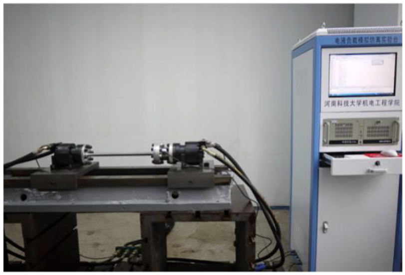
Simulation test-bed of passive electro-hydraulic force servo system.

The influence of different speeds of the bearing system on coupling torque: (a) ωmax = 6.28°/s, (b) ωmax = 62.8°/s, and (c) ωmax = 251.2°/s.
The principle of synchronous structure decoupling
Through the above analysis, it can be seen that the active movement of the bearing system and the hysteresis of loading system are the fundamental reasons of coupling torque. It is difficult to solve the problem of coupling torque by means of control compensation methods, and the fundamental method of suppression must be found from the structure. As shown in Figure 2 and formula (1), if the loading motor can follow the movement of the bearing motor and can achieve load at the same time, this can offset the speed disturbance of bearing motor. Therefore, insert a synchronous motor into the outer layer of the loading motor in Figure 1; it forms a double-layer servo motor of the compound structure. Wherein the inner layer is used to load and the outer layer keep synchronization with the bearing motor. It can be implemented from the loading principle to change the passive loading into active loading and solved the coupling torque of the passive electro-hydraulic force servo system essentially. The concrete realization method is in the simulation, give the synchronous motor the same position command signal as the bearing motor, the synchronous motor and bearing motor respectively do closed-loop control, through the control algorithm to ensure the both synchronous movement, at the same time, the torque closed-loop control is applied to the loading motor according to certain loading gradient. In this article, it is named compound synchronous loading servo motor, which can achieve the function as above, it is structural and oil circuit principle diagram, as shown in Figure 5.
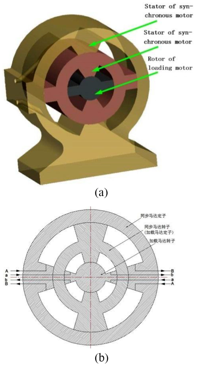
Compound synchronous load servo motor structure and oil circuit principle diagram: (a) principle diagram of structure and (b) principle diagram of oil circuit.
Figure 5 shows that compound synchronous loading servo motor is a double nested structure of compound swing motor, the outer layer is synchronous motor, and inner layer is loading motor. The rotor of the synchronous motor is also used as the stator of loading motor. The stator of loading motor; the shell and the rotor of the synchronous motor are designed into an integrated structure. The rotor of loading motor is connected rigidly with the rotor of bearing motor.
In the work, as long as the synchronous motor is synchronized with the bearing motor, that is the synchronous motor is remained “relatively static” with bearing motor. Then the forced flow is absorbed by following movement of synchronous motor, which generated due to the passive movement of the loading motor, the coupling torque between loading system and bearing system is released. At this time, the passive loading becomes active loading, and effectively eliminating the coupling torque caused by the active motion of the bearing system.
Parameters matching principle and structure design of compound swing motor
Parameters matching principle of compound swing motor
The key to eliminating coupling torque in the compound swing motor is to ensure the synchronous motion of synchronous motor and bearing motor. Theoretically, not only the angular velocity of the synchronous motor and the bearing motor should be equal, but also the changing trend of angular velocity should keep the same, even the changing trend of angular acceleration should be the same. When the motor starting, reversing, and stopping, it is more difficult to ensure synchronous movement because of the difference of the two motor friction torque and response speed. Therefore, in order to ensure the synchronous control precision between synchronous motor and bearing motor, the structural parameters of two motors must be completely consistent. However, due to the compound swing motor adopt double nested structure. It is impossible to ensure the structural parameters of two motors completely consistent, which lead to the difference of the friction torque between the two motors. Therefore, the design of compound swing motor must be to ensure the response speed same of between synchronous motor and bearing motor, match the parameters according to the principle of natural frequency and damping ratio, the friction of the synchronous motor is reduced as much as possible in order to guarantee the rapidity of tracking the bearing motor.
Structure design of compound swing motor
According to the structural principle and parameters matching principle of the compound swing motor, the structural parameters of outer layer synchronous motor must be able to achieve synchronous control with bearing motor, and the structural parameters of inner layer loading motor must be able to meet the loading performance of the system. At the same time, the inner layer loading motor is suited inside the outer layer synchronous motor. Considering the layout of the servo valve and position detection element, the setting of the oil duct, and the sealing mode, the structure of the compound swing motor is designed as shown in Figure 6, and structure parameters as shown in Table 2.
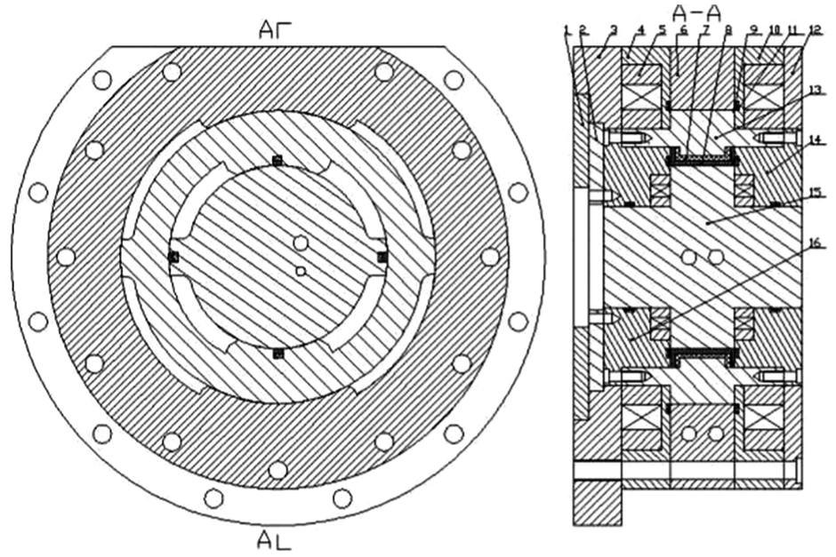
The structure diagram of compound swing motor.
The structure parameters of compound swing motor.

As shown in Figure 6, the loading motor suit is in the rotor of the synchronous motor, in which the synchronous motor rotor is used as the loading motor shell. The induction synchronizer rotor is connected with the left end cap of the loading motor, the inner loading motor chooses the load motor rotor to distribute oil, and the outer synchronous motor chooses the shell to distribute oil. The synchronous servo valve is arranged on the surface of the synchronous motor shell, and the loading servo valve is arranged on the rotor of the loading motor through a hydraulic rotating joint. Compared with single layer motor, the double suit structure has longer leakage and seal boundary, and the structure of the suit increases the design difficulty of the structure and the oil duct.
The sealing of compound swing motor
Because the compound swing motor is a double nested structure, the sealing area is approximately twice that of a single-layer motor, and the static friction torque becomes large. Excessive static friction torque makes it difficult to start the motor and reduces the low speed performance of the motor, and affects the reduction of coupling torque. Therefore choosing the right sealing type is a key issue in the design of a compound swing motor.
The gap seal and the packing seal are the two most commonly used kinds of dynamic seals in motor. The friction torque of the gap seal is small, the structure is simple, the service life is long, and the solid phase friction is not occurred. Packing seal is reliable, friction torque is large, and installation maintenance is convenient. Loading motor requires output instruction loading torque, and leakage will cause larger error in output torque. The synchronous motor need to ensure the synchronization accuracy with the bearing motor, the faster it response the better, and the smaller it starting friction torque the better. Considering the above factors, the outer layer synchronous motor chooses the gap seal, and the inner layer loading motor chooses the combination seal of packing. The combination seal of compound swing motor usually consists of a main seal and an auxiliary elastic sealing element. It belongs to the type contact self-tightening seal. The compression deformation after the installation of the O-ring is applied to the inside of the main seal and makes the main seal closely contact with synchronous motor rotor. 21
Oil duct design of the loading motor
Loading motor is suit inside the synchronous motor, and synchronous motor rotor is used as loading motor shell, so the loading motor adopts the axial flow mode, as shown in Figure 7.Through offset the oil duct of loading motor, it can generate a buffer zone in geometric mutant zone, which is equivalent to the chamfering of the oil duct, and it helps to reduce the pressure and flow rate mutation in the geometric mutation zone. Setting the offset distance is the radius of the oil duct, which makes the over-flow area largest in the mutation zone of oil duct, and the local pressure loss is the minimum, and it will not produce throttling effect at the same time.

Profile diagram of loading motor oil duct.
Since the loading motor oil passage is arranged on the rotor shaft, so choose the hydraulic rotary joints to distribute the loading motor, the hydraulic rotary joint spindle follows the loading motor rotor swing, and the shell is fixed. In order to reduce the invalid volume and increase the response speed of the loading motor, the loading servo valve is installed on the shell of hydraulic rotary joint.
Oil duct design of the bearing motor
The rotor of the synchronous motor is hollow, and the inside of rotor is loading motor, so the oil duct of synchronous motor is set in the shell. There are three oil duct setting modes, as shown in Figure 8.
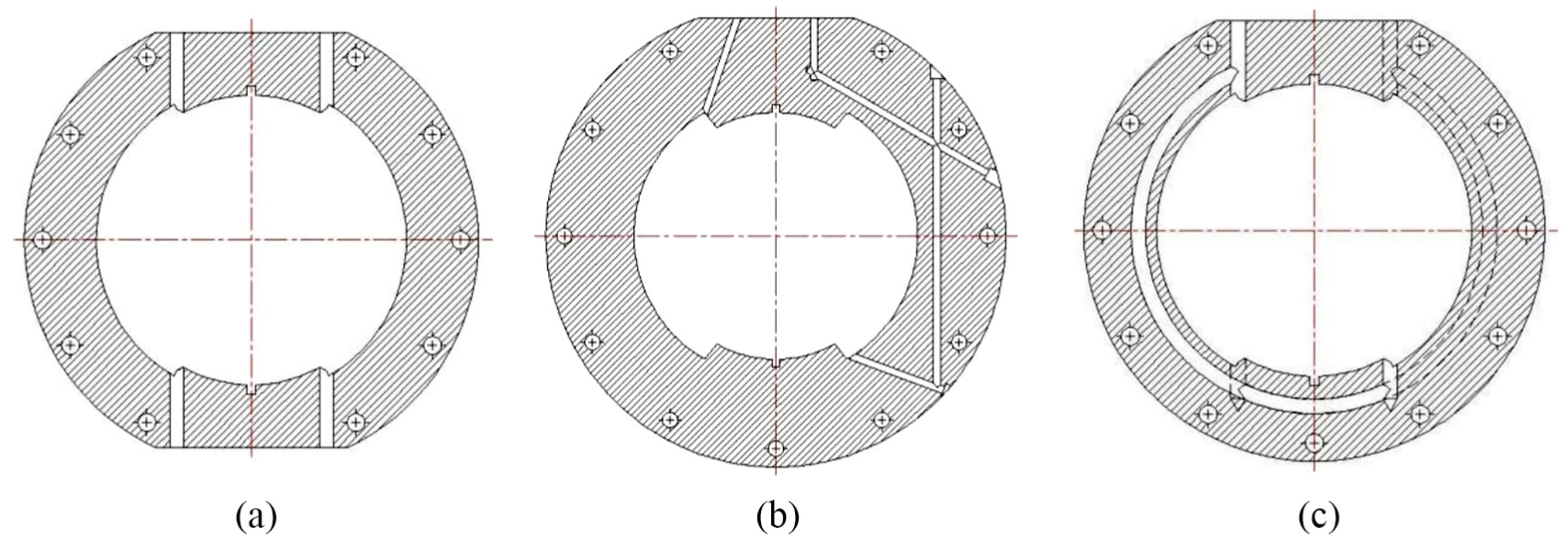
Profile diagram of synchronous motor oil duct: (a) oil duct setting mode 1 of synchronous motor, (b) oil duct setting mode 2 of synchronous motor, and (c) oil duct setting mode 3 of synchronous motor.
The oil distribution method shown in Figure 8(a) simplifies the synchronous motor oil passage, reduces the pressure loss, but symmetrical oil passages need to be provided on the synchronous motor case, increasing the number of external tubing and void volume, affecting the response characteristics of synchronous motors, and making it difficult to arrange the synchronous servo valve. The oil duct shown in Figure 8(b) is set inside the synchronous motor shell. It avoids the disadvantages of Figure 8(a), but there are geometric mutations in this oil duct, and the mutations are acute angle, larger local pressure loss will be produced. In addition, due to the synchronous motor internal pressure is high and reversing frequently, the geometric mutation zone stress concentration and changes frequently, resulting in geometric mutation is easy to appear at the metal erosion seriously and pollute the oil, resulting in servo valve fault. The arc-shaped oil duct shown in Figure 8(c) is set inside the synchronous motor shell, the pressure loss is smaller, and the mechanical processing way is difficult to achieve. Synchronous motor shell can be used precision casting and can ensure the surface precision of oil duct at the same time. In summary, the oil duct setting mode 3 as shown in Figure 8(c) is adopted. In order to improve the response speed of the synchronous motor, the synchronous servo valve is integrated into the synchronous motor shell.
Fluid characteristic analysis of compound swing motor
Through the analysis above, it can be seen that the oil duct setting is the emphasis and difficulty of the compound swing motor and it directly affects the ability of the compound swing motor to eliminate the coupling torque. Therefore, it is necessary to analyze its fluid characteristics so as to verify the rationality of oil duct setting for compound swing motor by ANSYS. The compound swinging motor model is imported into ANSYS FLUENT to generate the fluid domain of the compound swing motor and divide the mesh. The RNG k–e model is used to describe the flow state of hydraulic oil in the compound swing motor, and the inside of the motor is No. 46 hydraulic oil. The pressure difference format adopts a standard discrete differential format; momentum equation, turbulent kinetic energy equation, and turbulent energy dissipation rate all adopts the first-order upwind difference scheme. The velocity and pressure equations are solved by the SIMPLE coupling algorithm. Set the standard of the continuity equation and the momentum equation convergence residual is 10-5, iteration step is 3000 steps, as shown in Figure 9, the residual converges at 2338 steps. The fluid characteristics of the compound swing motor are shown in Figure 10.

Calculating residuals curve of RNG k–e.

Velocity and pressure nephogram of compound swing motor: (a) velocity nephogram of compound swing motor and (b) pressure nephogram of compound swing motor.
The velocity nephogram is seen from Figure 10(a), the velocity streamline of synchronous motor fluid domain is parallel to each other, and the oil flow is stable. When the fluid flows through each turn, the flow area of the fluid domain will be changed, so the flow velocity will be changes as well. It can be seen from the streamline chart that the velocity of the flow in the near wall of the oil duct is relatively faster at the turn, but the shape of the streamline is not destroyed, and no larger vortex is produced. From the streamline distribution of the loading motor, the fluid flow has no larger vortex, and the streamline is stable. The pressure nephogram is seen from Figure 10(b), there is no greater local pressure loss in the geometry mutation zone of the two motors oil duct, and the total pressure loss of the fluid flow is very small. The accuracy of the loading torque of the inner layer loading motor is guaranteed.
The synchronous structure decoupling simulation analysis of compound swing motor
The synchronous structure decoupling strategy can be changed from passive load to active load, thus eliminate the coupling torque of the passive electro-hydraulic force servo system theoretically. In order to verify the effectiveness of the compound swing motor in eliminating coupling torque, built an AMESim simulation model of passive electro-hydraulic force servo system which uses a compound swing motor as the loading device. Due to the large proportion of coupling torque in the low grads loading, it is more difficult to meet the loading performance. Therefore, take low grads loading as an example to analyze the effectiveness of eliminating the coupling torque using compound swing motor as the loading device. The AMESim model of synchronous structural decoupling of compound swing motor is shown in Figure 11.

AMESim model of synchronous structure decoupling.
The right side is the loading motor, the upper left side is the synchronous motor, the lower left side is the bearing motor, the synchronous motor rotor is connected with the loading motor shell through the rotating load, and the bearing motor rotor is connected with the loading motor rotor through the rigid shaft. In the model, the compressibility of the oil and the internal leakage of the swing motor are considered, and the internal leakage is set to the slit flow. The simulation parameters are obtained from Tables 1 and 2. The loading gradient is 2 N m/°, and the angular displacement signal is sin πft. The response curve of bearing motor and loading motor is shown in Figure 12 in the three different frequencies of 5, 10, and 16 Hz.
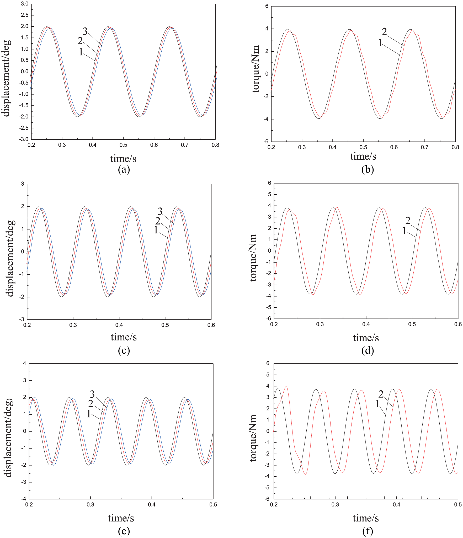
Displacement and torque response curves with synchronous structure decoupling strategy under different frequencies: (a) f = 5 Hz, displacement response curve; (b) f = 5 Hz, torque response curve. (c) f = 10 Hz, displacement response curve; (d) f = 10 Hz, torque response curve; (e) f = 16 Hz, displacement response curve; and (f) f = 16 Hz, torque response curve.
In the displacement response curve, the curve 1 represents the displacement command signal, the curve 2 represents the displacement response of the bearing motor, and the curve 3 represents the displacement response of the synchronous motor. In the torque response curve, the curve 1 represents the torque command signal, and the curve 2 represents the torque response of the loading motor.
It can be seen from Figure 12 that the response curves of displacement and torque have different degrees of hysteresis under different frequencies. This is mainly due to the inherent frequency limitation of the loading system, which is determined by the bandwidth of the system itself. The coupling torque of the passive electro-hydraulic force servo system can be relieved using the compound swing motor perfectly in the low frequency band. With the increase of loading frequency, the tracking performance of the loading system has decreased, but the amplitude attenuation is within 10%, phase lag is less than 10°, and it can still meet the double ten index in the performance index of the passive electro-hydraulic force servo system. It can be seen that the synchronous structure decoupling strategy can effectively eliminate the coupling torque of the passive electric–hydraulic force servo system.
Conclusion
Through the analysis of the mathematical model of the passive electric–hydraulic force servo system, the generating mechanism of the coupling torque is revealed, and the influence rule of each parameter on the coupling torque is given.
Put forward a new principle of passive loading based on new loading execution component. The coupling torque problem is solved by the structural decoupling strategy thoroughly which transforms passive loading into active loading. The principle of parameters matching between compound swing motor and bearing motor is given, the motor structure scheme is designed, and the sealing technology and internal flow construction method of compound swing motor are studied.
The feasibility and effectiveness of the new loading principle are proved by the simulation analysis, which lays the foundation for the future load simulation technology development.
Footnotes
Handling Editor: Pietro Scandura
Declaration of conflicting interests
The author(s) declared no potential conflicts of interest with respect to the research, authorship, and/or publication of this article.
Funding
The author(s) disclosed receipt of the following financial support for the research, authorship, and/or publication of this article: This study was supported by the National Natural Science Foundation of China Program (51175148) and State Key Laboratory of Shield Machine and Boring Technology Open Topic (2014-03).