
Abstract
In automated manufacturing systems, resource failures are often inevitable. They reduce the number of available resources and may cause some processing routes of parts to halt and sometimes the whole system to shutdown. This article focuses on the robust deadlock control problem in automated manufacturing systems with multiple resource failures. To obtain such a robust controller, we first put forward a new concept of blocked states of automated manufacturing systems. From such a state, the production of some part types through one of their routes is blocked as caused by resource failures, and only after some failed resources are repaired, these parts can resume their normal processing. Then, these blocked states are characterized in terms of emptied siphons caused by resource failures. In order to prevent the system from deadlocks and blocked states, a robust controller is proposed by the following two steps. First, for siphons without unreliable resources, optimal deadlock control places are added. Then for siphons which contain unreliable resources, new control places are devised to ensure that they could be marked even when resource failures happen. It is proved that the proposed controller can guarantee that all types of parts can be processed repeatedly as long as one unit of unreliable resources can still work. This means that the proposed controller is of greatest robustness, that is, it can tolerate a maximum number of resource failures. Some examples are provided to illustrate the proposed method and show the advantage over the previous ones.
Introduction
Automated manufacturing systems (AMS) are modern production facilities which are highly adaptable to variable production plans and goals. Due to the competition of shared resources in AMS, deadlocks may occur, leading to unnecessary cost or even catastrophic results. Besides, AMSs have many types of components such as a sensor, an actuator, a tool, and so on which can fail unexpectedly, and any of the failure can cause an unexpected and unpredictable disruption. Therefore, it is highly important to develop an efficient controller to avoid these deadlock situations and guarantee the normal production of the system while resource failures happen.
It is well known that Petri nets (PNs) represent an important and popular mathematical model for modeling and analyzing discrete event systems, particularly AMS. Thus, many researchers adopt PN as a formalism to describe AMS and develop appropriate deadlock control methods and scheduling algorithm,1–6 resulting in a wide variety of approaches.
Majority of deadlock control methods can be classified into two categories, namely, deadlock prevention7–11,27 and deadlock avoidance.12–14,28 However, in these deadlock control methods mentioned above, all the resources are assumed to be reliable, while real-world AMS may contain unreliable resources. When an AMS suffers resource failures, some or all of its processes might be blocked until these failed resources are repaired. Since resources repair may take a long time, these blocked states (BSs) reduce the efficiency of production. Consequently, it is necessary to develop an effective supervisory controller for AMS with unreliable resources, called as robust deadlock controller, to guarantee that all part types can be processed repetitively through any one of their process routes even when resource failures happen.
Some researchers have studied on the robust deadlock control of AMS with unreliable resources.15–23 Generally speaking, according to the ways to model resource types, they can be divided into two categories. In Lawley and Sulistyono, 18 resource types are modeled as workstations, one workstation is composed of one machine and multiple buffer spaces, and resource failure implies the failure of the workstation’s machine, not its buffer spaces. For this kind of AMS, Lawley and Sulistyono proposed a robust supervisory control policy. Neighborhood constraints and Banker’s Algorithm are used to guarantee that when the unreliable resource fails, the system can continue to produce all part types not requiring it. Many other researchers have also studied this kind of system and have achieved some results.15,20,22–24 While for another kind of AMS,16,17,19,21 resource types are modeled as machines, one resource type may contain multiple machines. For this kind of AMS, Hsieh 17 analyzed the fault-tolerant property of controlled assembly PNs and proposed an algorithm to handle unavailability of resources. Liu et al. 19 used recovery subnets to describe the resource failure and recovery in system of simple sequential processes with resources (S3PR) with unreliable resources. Based on the concept of transition cover, 2 Feng et al. 16 obtained a 1-robust PN controller for S3PR with a single unreliable resource, and it can ensure that the system can process all types of parts infinitely even if one of unreliable resources fails. Wu et al. 21 reports a novel approach to obtain a 1-robust controller such that the controlled system can still work normally even if one resource failure happens.
The controller in Wu et al. 21 suffers from the following two shortcomings: First, it overly restricts the permissive behavior of a PN because the output arcs of a controller are all led to the source transitions of the net, which limits the number of workpieces to be released into and processed by the system at a time. A source transition is the output of an idle place, which models the entry of raw parts into the system. Second, its robustness is too limited and not practical, since it only consider the case of at most one unit of resource failure, while real AMS may suffer from multiple resource failures. In order to handle the considered two shortcomings and to achieve a widely industrial applicability, this article proposes a multiple robust controller with more permissive behavior.
This article focuses on the robust deadlock control problem in AMS with a single type of unreliable resource. We consider only the case that an unreliable resource (machine or robot) can fail, but its buffer can still be assigned workpieces, and then resource failures in operation places are analyzed. The concept of a k-robust controller is defined. It guarantees repeated processing of all part types when most k units of the unreliable resource fail to work. After any number of failed resource units are repaired, they can be returned to the system to continue working. For an AMS with single type of unreliable resource ru, this article presents how to design a robust controller, which can make sure that the whole system can produce products as long as one unit of unreliable resource can work.
This work makes two improvements over the approach in Wu et al.: 21 First, the robust controller in this work is more permissive than controllers in Ezpeleta et al., 7 Liu et al., 10 and Wu et al. 21 Note that the controllers in Ezpeleta et al. 7 and Liu et al. 10 are proposed for AMSs with reliable resources, and hence, no robustness, while the controller proposed in this article is robust for unreliable systems. Experimental study indicates that even for reliable AMS, the proposed controller in this article is more permissive than those non-robust controller. Second, this article improves the robustness level (RL) of the controller, from 1 in Wu et al. 21 to Ψ(ru) −1, where Ψ(ru) is the capacity of unreliable resource ru. The proposed robust controller can ensure continuous processing of all types of parts as long as one unit of unreliable resources can work. To the best of our knowledge, it is the first one with greatest robustness, that is, it can tolerate a maximum number of resource failures.
There are two major differences between this work and those in Wang et al., 20 Yue and Xing, 22 and Yue et al.: 23 First, the classes of AMSs considered are different. In Wang et al., 20 Yue and Xing, 22 and Yue et al., 23 a resource type is one machine with buffer spaces and resource failure means the machine failure, not any of its buffer space. When the resource fails, it cannot process any parts, but its buffer space can still be used, while in this work, unreliable resources are only machines and robots without buffer spaces. Second, since the considered systems are different, the control objectives are completely different. In Wang et al., 20 Yue and Xing, 22 and Yue et al., 23 the objective is to develop a control policy that allocates resources so that the failure of any given resource does not propagate through blocking to effectively stall other portions of the system. In other words, when a resource fails, they want the system to automatically continue producing all part types that do not require the failed resource. While in this article, we must ensure that the system can produce all types of parts even if Ψ(ru) − 1 unreliable resources are failed.
The class of AMSs considered in this article is the same as Feng et al. 16 and Wu et al., 21 but the performance of the proposed controller is better than that of controllers in Feng et al. 16 and Wu et al. 21 The controller proposed in this article permits more reachable markings than controllers in Feng et al. 16 and Wu et al. 21 Meanwhile, the proposed controller has a higher RL, up to Ψ(ru)−1, while controllers in Feng et al. 16 and Wu et al. 21 have only 1, that is, they only considered the case where one unit of unreliable resources may fail.
The rest of this article is organized as follows. Some basic PN definitions are recalled in the next section. Then, we analyzed the BSs in S3PR with single type of unreliable resources and proposed a novel robust controller. Two examples are given and the results and principal outcomes of this article are discussed. The last section concludes this article.
Basic definitions of PNs
This section recalls some basic definitions and properties of PNs, S3PRs, and resource-transition circuits (RTCs). The reader is referred to Ezpeleta et al., 7 Han et al., 8 Xing et al., 14 and Zhou and Venkatesh 25 for more details.
PNs
A PN is a four-tuple N = (P, T, F, W), where P and T are finite sets of places and transitions, respectively. F⊆ (P×T) ∪ (T×P) is the set of directed arcs. W: F→Z + is an arc weighted function, where Z+ denotes the set of positive integers. N is pure or self-loop free if (x, y) ∈F implies (y, x) ∉F; N = (P, T, F, W) is ordinary if ∀f∈F, W(f) = 1, and in this case, W can be omitted. In this article, all the studied PNs are pure and ordinary. A pure net structure can be described by its incidence matrix [N], and it is a [P] × [T] integer matrix with [N](p, t) = W(t, p) − W(p, t).
Given a node x∈P∪T, the preset of x is defined as •x = {y∈P∪T | (y, x) ∈F}, and the postset of x is defined as x• = {y∈P∪T | (x, y) ∈F}. These notations can be extended to a set, for example, if X⊆P×T, then •X = ∪x∈X•x and X• = ∪x∈Xx•. A state machine is a PN in which each transition has exactly one input and one output place.
Let S be a nonempty subset of places and S is a siphon (trap) if •S⊆S• (S•⊆•S). A siphon is said to be minimal if it contains no other siphons as its proper subset. A minimal siphon is said to be strict if it does not contain a trap. A strict minimal siphon is denoted as SMS for short.
Let Z = {0, 1, 2, …}, and Zk = {1, 2, …, k} for a given positive integer k. A path x1, …, xn is a string where xi + 1∈xi•, i∈ Zn–1. A simple path is a path whose nodes are all different (except x1 and xn). A path x1, …xn is called a circuit if it is a simple path and x1 = xn.
A marking or state of N is a mapping M: P→ Z. A PN N with an initial marking M0 is called a marked PN, denoted as (N, M0). Given a place p∈P and a marking M, M(p) denotes the number of tokens in p at M. For B⊆P, let M(B) = Σp∈BM(p).
Given a marking M, a transition t is enabled at M if ∀p∈•t, M(p)≥W(p, t), and this fact can be denoted by M[t>. An enabled transition t at M can fire, resulting in a new marking M′, which is denoted by M[t>M′. A marking M is said reachable from M0 if there exists a sequence of transitions σ such that M0[σ>M holds. Let R(N, M0) be the set of markings reachable from M0 in N. A transition t is live if ∀M ∈ R(N, M0) and ∃M′ ∈ R(N, M) so that M′[t>. A transition t is dead at M ∈ R(N, M0) if ∀M′ ∈ R(N, M), M′[t>does not hold. (N, M0) is said to be live if every transition of it is live.
A P vector is a column vector I: P → Z indexed by P, where Z is the set of integers. P vector I is called a P-invariant if I ≠
The composition of two PNs, Ni = (Pi, Ti, Fi), i∈{1, 2}, via the same elements, denoted as N1⊗ N2, is a PN N1 ⊗ N2 = (P, T, F), where P = P1∪ P2, T = T1∪ T2, and F = F1∪ F2. Two marked PNs, (Ni, Mi0) = (Pi, Ti, Fi, Mi0), i ∈ {1, 2}, are compatible if ∀p ∈ P1 ∩ P2, M10(p) = M20(p). The composition of two compatible PNs (N1, M10) and (N2, M20) is a marked PN (N1, M10) ⊗ (N2, M20) = (N1 ⊗ N2, M0), where M0(p) = M10(p), ∀p ∈ P1 and M0(p) = M20(p), ∀p ∈ P2.
S3PR class
Definition 1
An S3PR is an ordinary PN (N, M0) = (P ∪ P0 ∪ PR, T, F, M0) defined as follows:
P ∪ P0 ∪ PR is a partition such that (1.1)
∀i ∈ Zm, the subset Ni generated by Pi ∪ {pi0}and Ti is a strong connected state machine, and every circuit of Ni contains pi0.
∀p ∈ P, ∀t1 ∈ •p, ∀t2 ∈ p•, •t1 ∩ PR = t2• ∩ PR ={r}, we say that p requires r, denoted as R(p) = r.
∀r ∈ PR, ••r ∩ P = r•• ∩ P ≠ ∅, •r ∩ r •= ∅, and ••(P0) ∩ PR = (P0) ∩ PR•• = ∅.
The initial marking M0 satisfies that (6.1) ∀p ∈ P0, M0(p) > 0; (6.2) ∀r ∈ PR, M0(r) = Ψ(r), let Ψ(r) be the capacity of resource r; and (6.3) ∀p ∈ P, M0(p) = 0.
For a resource r ∈ PR, let H(r) denote the set of all operation places that require resource r, that is, H(r) = {p ∈ P | R(p) = r}. This notation can be extended to sets, for example, if R′ is a set of resources, H(R′) = ∪r∈R′H(r). Let (p)t = •t∩P, (r)•t = t ∩ PR, and M ∈ R(N, M0). t is said to be process-enabled (resource-enabled) at M if M((p)t) > 0 (M((r)t) > 0). Let Ξ(N) be the set of all SMSs in (N, M0). For S ∈ Ξ(N), the complementary set of S is denoted as [S] = H(SR)\S, where SR = S∩PR, SP = S∩P.
An operation path in N is a path containing only operation places and transitions. Let x, y ∈ P ∪ T. x is previous to y if there exists an operation path from x to y, denoted as x ≤Ny; in this case, we have x ≤Nx. Let A ⊆ P ∪ T, we say that x ≤NA if there exists a node y ∈ A such that x ≤Ny, and A ≤Nx if there exists a node y ∈ A such that y ≤Nx.
Deadlock controller for S3PR
Let θ be a circuit in an S3PR (N, M0) and M ∈ R(N, M0). θ is called a RTC if it contains only resource places and transitions. Let ℑ[θ] and ℜ[θ] denote the set of all transitions and resource places in θ, respectively.
An RTC θ is a perfect RTC (PRTC) if it satisfies ((p)ℑ[θ]) •= ℑ[θ]. Let ϑ(R1) denote the set of all PRTC with resource set R1. If θ1, θ2 ∈ R1, then the union of θ1 and θ2 is a PRTC with resource set R1, that is, θ1 ∪ θ2 ∈ ϑ(R1). Therefore, ϑ(R1) contains a unique maximal PRTC (MPC). Let ϑ(N) denote the set of all MPCs in N.
An MPC θ is said to be saturated at marking M if M((p)ℑ[θ]) = Ψ(ℜ[θ]). Let θ∈ϑ(N) and t ∈ T, t is called an input of θ if its firing increases the number of tokens in (p)ℑ[θ] and an output one if its firing decreases the number of tokens in (p)ℑ[θ]. Let I(θ) and O(θ) denote the sets of input and output transitions of θ, respectively.
It has been proved in Xing et al. 26 that there exists a one-to-one corresponding between Ξ(N) and ϑ(N). For θ ∈ ϑ(N), let g(θ) be the SMS corresponding to θ, then we have g(θ) = ℜ[θ] ∪ (H(ℜ[θ])\•ℑ[θ]), and [g(θ)] = (p)ℑ[θ]; similarly, let h(S) be the MPC corresponding to S, then we have h(S) = N[SR ∪ {•SR\SP•}], and N[SR ∪ T(S)] be a subset of N generated by SR ∪ {•SR\SP•}. Let I([S]) = I(θ) and O([S]) = O(θ) denote the sets of input and output transitions of [S], respectively.
Let (N, M0) = (P ∪ P0 ∪ PR, T, F, M0) be an S3PR, and M ∈ R(N, M0). M is safe if M0 ∈ R(N, M). A transition t ∈ T at a safe marking M is safe if M[t > M′ and M′ is safe.
Definition 2
Let (N, M0) be an S3PR, r ∈ PR is a κ-resource if M0(r) = 1 and there exists a sequence of MPCs θ i (i∈ Z k , k≥ 2) in ϑ(N) satisfying
{r} = ∩i∈Zkℜ[θ i ];
Ti = {t | t∈ℑ[θi] ∩I(θi+1), (r)t = r} ≠∅, i∈Zk and subscripts are mod k;
A κ-resource is a one-unit resource shared by two or more MPCs in a special way. The following lemma states that if an S3PR contains no κ-resources, then every unsafe state in it is a deadlock.
Lemma 1
An S3PR (N, M0) = (P ∪ P0 ∪ PR, T, F, M0) without κ-resources contains only two kinds of reachable markings: safe ones and deadlocks. 8
From Lemma 1 we know that in order to avoid deadlocks in an S3PR without κ-resources, the controller only needs to forbid transitions firing that lead the system from safe markings to deadlocks. Such a controller can be designed as follows.
Definition 3
Let (N, M0) = (P ∪ P0 ∪ PR, T, F, M0) be an S3PR without κ-resources.
1. Define a PN controller for S ∈ Ξ(N)

where cS is a control place corresponding to S, its initial marking is MS0(cS) = Ψ(S R ) – 1, TS = I([S]) ∪O([S]), and FS = {(cS, t) | t ∈ I([S])}∪{(t, cS) | t∈O([S])}.
2. Define a PN controller for (N, M0)

Let (CN, MCN0) = (N, M0) ⊗ (C, MC0) be the controlled PN, and M ∈ R(CN, MCN0), for S ∈ Ξ(N), {cS} ∪ [S] is a support of p-invariant in (CN, MCN0), and for any M∈R(CN, MCN0), M(cS) + M([S]) =MC0(cS) = Ψ(SR) – 1.
Lemma 2
Let (N, M0) be an S3PR without κ-resources. 8 Then, the controller (C, MC0) for it in Definition 3 is the optimal deadlock controller for (N, M0).
Example 1
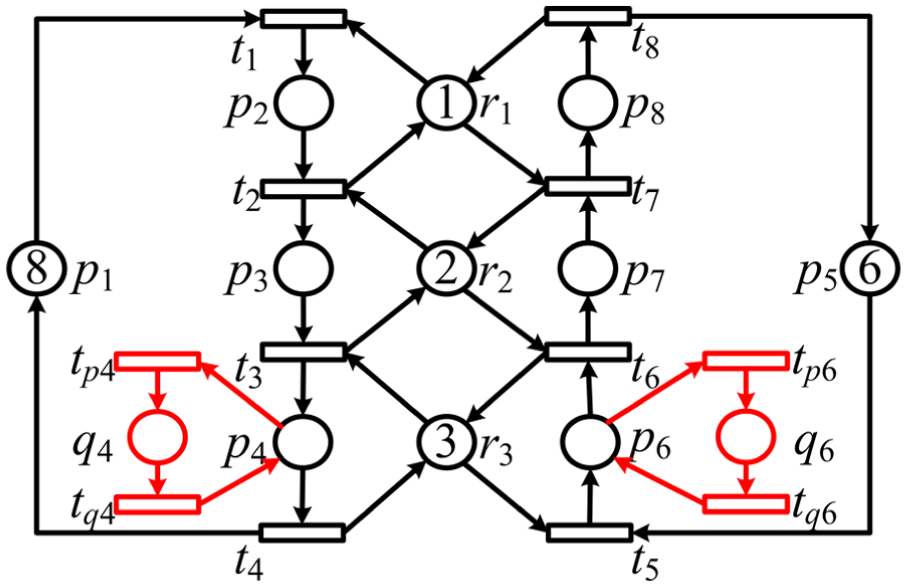
An AMS cell shown in Figure 1(a) can process two types of parts Δ1 and Δ2, each processing line consists of three machines r1, r2, and r3 with capacities 1,2, and 3, respectively. Each machine can process one part at a time. Parts enter the cell through uploading buffer

(a) An AMS cell, (b) an S3PR, and (c) the controller.
The net shown in Figure 1(b) is an S3PR without κ-resources. It has three SMSs: S1 = p3p8r1r2, S2 =p4p7r2r3, and S3 = p4p8r1r2r3. This PN has 166 reachable markings with 154 safe markings in it. For siphon S1, we have [S1] = {p2, p7}, I([S1]) = {t1, t6}, and O([S1]) = {t2, t7}. For M ∈ R(CN, MCN0), MC0(cS1) +MC0([S1]) is a p-invariant; hence, FS1 = {(cS1, t1), (cS1, t6), (t2, cS1), (t7, cS1)}.
Similarly, we can get I([S2]) = {t2, t5}, O([S2]) = {t3, t6}, I([S3]) = {t1, t5}, and O([S3]) = {t3, t7}. The optimal PN deadlock controller (C, MC0) in Definition 3 is shown in Figure 1(c). All 154 safe markings are reachable under the control of (C, MC0).
For S3PR with κ-resources, a κ-resources elimination method is proposed in Han et al. 8 and Xing et al. 14 for reducing κ-resources so that the reduced PN does not contain κ-resources but still falls into the class of S3PRs. This method is shown as follows.
Definition 4
Let (N, M0) = (P ∪ P0 ∪ PR, T, F, M0) be an S3PR and r be a κ-resource. The reduced net of (N, M0) on r is a PN (NA, MA0) = (PA ∪ P0 ∪ PAR, TA, FA, MA0) which can be obtained by the following steps.
Delete r and its related arcs from N, and let PAR = PR\{r}.
For each transition t ∈ PAR•∩•r, for example, r1 ∈ PAR such that (r1, t) ∈F and (t, r) ∈F, delete (r1, t) from S3PR. Let pf = (p)t. If |pf•| = 1, then ∀tf ∈ pf•, add (r1, tf) if (tf, r1) ∉F or delete (tf, r1) if (tf, r1) ∈F, rename r1 to mr1 (mean as modified resource place), and let R(κ) be the set of all modified resources. If |pf•| = k > 1, let pf• = {t1, t2, …, tk} and (r)ti = ri, i∈Zk, and then, replace pf with k operation places, ∀tf ∈ pf, delete pf• and its related arcs and add k operation places, denoted as pf1, pf2, …, pfk. Let pf0 = (p)tf, R(pf0) = rf. Delete tf and its related arcs, add k transitions, denoted as tf1, tf2, …, tfk (in this case, we will say that tf is separable and is separated into tf1, tf2, …, tfk), and add arcs (pf0, tfi), (t fi , pfi), (pfi, ti), (ri, tfi), and (t fi , rf), i∈Zk. Let Tf⊆T denote the set of all separable transitions in N. If for a resource place r′ and a transition place t′ such that (r′, t′) and (t′, r′) exist at the same time, then delete (r′, t′) and (t′, r′).
After steps 1 and 2, the sets of all the existing operation places, transitions, and arcs are denoted as PA, TA, and FA, respectively. MA0 is the initial marking of NA, under which only places in P0∪PAR are marked as in (N, M0).
Then, a deadlock supervisory policy for S3PR with κ-resources can be defined as follows.
Definition 5
Let (N, M0) = (P ∪ P0 ∪ PR, T, F, M0) be an S3PR and r be a κ-resource. (NA, MA0) be the reduced PN without κ-resource, (Cr, MCr0) be the optimal deadlock prevention controller of (NA, MA0), and let (CNA, MCA0) = (NA, MA0) ⊗ (Cr, MCr0). Define a supervisory policyζ as follows.
∀t∈T\Tf, ζ permits firing of t in (N, M0) ⇔t can be fired in (CNA, MCA0). t fires in (N, M0) and (CN A , MCA0) at the same time.
∀tf∈Tf, ζ permits firing of tf in (N, M0) ⇔ one of tf1–tfk can be fired in (CNA, MCA0), where tf is separated into k transitions tf1–tfk, tf fires a time ⇔ one of tf1–tfk fires once in (CNA, MCA0).
Let ζ||(N, M0) denote (N, M0) supervised under ζ. Then, ζ is the liveness supervisor for (N, M0).
PN-based deadlock analysis for AMS with single type of unreliable resources
In this section, we first develop a PN model of the considered AMS with single type of unreliable resources and then analyze its liveness.
Let A(ru) denote the considered AMS with single type of unreliable resources ru. Note that in the absence of resource failures, A(ru) can be modeled by an S3PR, while the resource failure and recovery activities can be modeled by the so-called failure and recovery net (FRN) defined as follows.
Definition 6
Let (N, M0) = (P ∪ P0 ∪ PR, T, F, M0) be the S3PR modeling A(ru) in the absence of resource failures. The FRN of ru is defined as (Nu, Mu0) = (H(ru) ∪ Q, TP ∪ TQ, Fu, Mu0), where Q = {qi | qi is a resource recovery place corresponding to pi∈H(ru)}, TP = {tpi | tpi is a transition corresponding to the resource failure in pi∈H(ru)}, and TQ = {tqi | tqi is a transition corresponding to the resource recovery in qi}. Fu = {(pi, tpi), (tpi, qi), (qi, tqi), (tqi, pi) | pi∈H(ru)} and Mu0(qi) = Mu0(pi) = 0, where pi∈H(ru).
Then, all activities in AMS can be modeled by (NU, MU0) = (N, M0) ⊗ (Nu, Mu0), called as the unreliable S3PR model of A(ru) or US3PR for short.
Let M∈R(NU, MU0) be a reachable marking of US3PR (NU, MU0), in this article, we define MN be the marking of (N, M0) at M, and MU be the marking of (Nu, Mu0) at M, and then, M can be rewritten as M = (M N , MU).
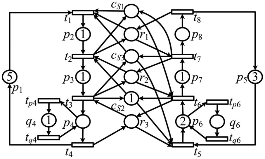
Let us reconsider S3PR shown in Figure 1(b). Assume that r3 is unreliable since H(r3) = {p4, p6}, we know that Q = {q4, q6}, TP = {tp4, tp6}, and TQ = {tq4, tq6}. For S1 = {p3, p8, r1, r2}, QS1 = Q[S1] = ∅; similarly, for S2 = {p4, p7, r2, r3}, QS2 = {q4} and Q[S2] = {q6}; and for S3 = {p4, p8, r1, r2, r3}, QS3 = {q4} and Q[S3] = {q6}. The US3PR is shown in Figure 2.
A US3PR.
In the remaining discussion, for an US3PR (NU, MU0), Ξ(N) only denotes those SMSs in (N, M0). For S ∈ Ξ(N), let QS = {q∈Q | •q∩S•≠∅} and Q[S] = {q∈Q |•q∈ [S]•}. Then, if ru∉S, QS = Q[S] = ∅; else, if ru ∈ S, Q[S] ∪ QS = Q.∀M ∈ R(NU, MU0), MU0(S) = M(S) + M([S]) + M(Q[S]) + M(QS).
In this work, our AMS control objective is to ensure that any kind of parts can be processed continuously through any one of their process routes even if some unreliable resource units fail. To this end, a kind of so-called robust controller is developed, and the concept of its RL is introduced. The RL of such a controller represents the number of how many units of failed resources can be tolerated by the controlled system, and it can be formally defined as follows.
Definition 7
Let (NU, MU0) be the US3PR model of A(ru), Λ be a controller for (NU, MU0) and Λ||(NU, MU0) be the controlled system. Then, for a integer k, Λ is called as a deadlock controller with robust level k or a k-robust controller for short, and if in the controlled system Λ||(NU, MU0), the following occurs:
Any kind of parts can be processed continuously through any one of their process routes when at most k units of ru fail;
When failed resources are repaired, they can be returned to the system, and their return would not affect the continuous processing of any kind of parts.
Note that if all units of ru fail, it is impossible to achieve the control objective. So, we assume that at any reachable markings of the unreliable system, at least one unit of ru can work normally. From Definition 7, we know that a deadlock controller for (N, M0) is a 0-robust controller for (NU, MU0). For example, the controller (C, MC0) in Definition 3 is a 0-robust controller for (NU, MU0).
A (k + 1)-robust controller is also k-robust, and all k-robust controllers are 0-robust. But the converse is not true. This can be shown in the following example.
Example 2
Consider (N U , MU0) = (N, M0)⊗(N u , Mu0) shown in Figure 2, where ru = r3. The optimal deadlock controller for (N, M0) is (C, MC0) as shown in Figure 1(c). It can be checked that (C, MC0) is 0-robust, but not 1-robust for (NU, MU0), since (NCU, MCU0) = (N U , MU0)⊗(C, MC0) can reach marking M1 as shown in Figure 3. At M1, one unit of r3 fails, M1(q4) = 1, and tokens in both process routes cannot move forward until the failed resource is repaired. Such a blockage is related to resource failures and the applied controller.
A reachable marking in the controlled net.
In this article, for the US3PR controlled by a 0-robust controller, reachable markings like M1 in Example 2 are called as BSs, formally defined as follows.
Definition 8
Let (NU, MU0) = (N, M0) ⊗ (N u , Mu0) be the US3PR model of A(ru), (C, MC0) be a 0-robust controller for (N U , MU0), (N CU , MCU0) = (N U , MU0) ⊗ (C, MC0) and M∈R(NCU, MCU0), and M = (MN, MU, MC), where MN, MU, and MC are markings of N, Nu, and C, respectively. Then, M is called a BS if (1) 0 < M(Q) < Ψ(ru) and (2) MN is a deadlock marking of (N, MN).
For (NU, MU0) and M∈R(NU, MU0), let RTP(NU, M) = {M′ | ∃α∈ (T∪TP)* such that M [α > M′}. That is, RTP(NU, M) is the set of reachable markings from M under the condition that no resource recovery happens. Then according to Definition 8, we can infer that for M ∈ R(NU, MU0), if there are no dead transitions at any marking of RTP(NU, M), then M is not a BS.
In Definition 8, condition (1) indicates that at any BS, at least one unit of unreliable resources has failed and condition (2) shows that the S3PR part of the US3PR has trapped into deadlock states because of resource failures, that is, unless at least one failed resources is repaired, the production on some processing route pauses. Take state M1 in Figure 3 as an example, we can see that M1(Q) = 1 > 0, and SMS S1 is empty at M1N, that is, M1N(S1) = 0, and all transitions in T are not enabled at any marking in R(N, MN).
There are mainly two differences between BSs and deadlocks. (1) BSs only occur when some units of unreliable resource are failed, while deadlocks may occur no matter whether resource failure happen or not. (2) BSs would not cause permanent blockage of the system, when the failure units are repaired and return to the system, those blocked process routes can be resumed, while deadlocks cause permanent blockage of the entire system.
For the US3PR controlled by a 0-robust controller, though all the deadlocks in (N, M0) are forbidden, the existence of BSs pauses some processing routes, and hence, such a controller cannot achieve the proposed control objective. Therefore, both BSs and deadlocks should be forbidden by ideal robust controllers.
Now, let us characterize BSs in the controlled US3PR with the controller proposed in Definition 3. For (NCU, MCU0) = (NU, MU0) ⊗ (C, MC0), where (C, MC0) is the optimal controller for (N, M0) in Definition 3. If M∈R(NCU, MCU0) is a BS, according to Definition 8, MN is a deadlock marking of N. Since a marked S3PR is live if and only if all siphons in it are not empty at any reachable markings, we have the following lemma.
Lemma 3
Let (NCU, MCU0) = (NU, MU0)⊗(C, MC0), where (NU, MU0) is an US3PR and (C, MC0) is its optimal 0-robust controller for (N, M0), M∈R(NCU, MCU0) and M is a BS. Then, there exists an SMS S∈Ξ(N) such that MN(S) = 0.
Proof
Since M is a BS, according to Definition 8, MN is a deadlock marking of (N, MN). Notice that a marked S3PR is live if and only if all siphons in it are not empty at any reachable markings. Then, there must exist an empty SMS at MN. Therefore, there exists an SMS S∈Ξ(N) such that MN(S) = 0.♣
According to Lemma 3, if all SMSs in (NCU, MCU0) are controlled to be not empty even if resource failures happen, all BSs can be forbidden.
According to whether SMSs contain places in H(ru), Ξ(N) can be divided into two disjoint subsets Ξ1 and Ξ2, where Ξ1 = {S | S∈Ξ(N), ru∈S, H(ru) ∩S≠∅}, and Ξ2 = Ξ(N)\Ξ1. Then φ[S] = [S] ∪H(ru) if S∈Ξ1; φ[S] = [S] if S∈Ξ2.
Take US3PR in Figure 2 as an example. There are three SMSs in (N, M0): S1 = {p3, p8, r1, r2}, S2 = {p4, p7, r2, r3}, and S3 = {p4, p8, r1, r2, r3}. r3 is unreliable, and H(r3) = {p4, p6}. Then, Ξ1 = {S2, S3} and Ξ2 = {S1}, φ[S1] = [S1] = {p2, p7}, φ[S2] = [S2] ∪H(r3) = {p3, p4, p6}, and φ[S3] = [S3] ∪H(r3) = {p2, p3, p4, p6, p7}.
From Definition 3, we can know that {cS∪ [S] ∪Q[S]} is the support of p-invariant in the controlled PN (NCU, MCU0), and hence, for M∈R(NCU, MCU0), M(cS) + M([S]) + MU(Q[S]) = MCU0(cS) = Ψ(SR) − 1. If M is a BS, according to Lemma 3, there exists an S ∈ Ξ(N) such that MN(S) = 0. Then, MU(QS) = MCU0(S) − (M([S]) + MU(Q[S])) = M(cS) + 1 > 0. That is, for (NCU, MCU0) and S ∈ Ξ(N), due to the fact that operation places in H(ru) ∩ S are not restricted, S may still be empty even if the number of tokens in [S] is no more than Ψ(SR) − 1.
Based on the discussions above, in order to forbid BSs and deadlocks, a robust controller should ensure that S\(H(ru) ∩ S) would not be empty, that is, the number of tokens in φ[S] should be limited.
Robust controllers design
Let (NU, MU0) = (N, M0)⊗(Nu, Mu0) be an US3PR. If (N, M0) does not contain κ-resources, for convenience, we also say that (NU, MU0) has no κ-resources.
In the following, we first develop robust controllers for an US3PRs without κ-resources and then for general US3PRs.
Robust controller for US3PR without κ-resources
For φ[S] = [S] ∪ (H(ru) ∩S), let ω(S) = {p | p∈P, p≤Nφ[S]} be the set of operation places which are previous to φ[S], and then, t is called an input of ω(S) if its firing increases the number of tokens in ω(S) and an output one if its firing decreases the number of tokens in ω(S). Let I(ω(S)) and O(ω(S)) denote the sets of input and output transitions of ω(S), respectively.
For an US3PR without κ-resources, its PN controller is defined as follows.
Definition 9
Let (NU, MU0) = (N, M0) ⊗ (Nu, Mu0) be an US3PR without κ-resources.
1. Define a PN controller for S∈Ξ1

where pS is a control place corresponding to S, its initial marking is MK0(pS) = Ψ(S) − 1, and TS = I(ω(S)) ∪O(ω(S)) and FS = {(pS, t) | t∈I(ω(S))} ∪ {(t, pS) | t∈O(ω(S))}.
2. Define a PN controller for S∈Ξ2

where (C[S], MS0) is the controller in Definition 3.
3. Define a PN controller for (NU, MU0)

Then, the controlled PN is (NC, MC0) = (K, MK0) ⊗ (NU, MU0).
Example 3
Consider US3PR (NU, MU0) = (N, M0) ⊗ (Nu, Mu0) shown in Figure 2, and ru = r3. Note that (N, M0) contains no κ-resource and has three SMSs: S1 = {p3, p8, r1, r2}, S2 = {p4, p7, r2, r3}, and S3 = {p4, p8, r1, r2, r3}. Then, Ξ1 = {S2, S3}, and Ξ2 = {S1}; ϕ[S1] = {p2, p7}, φ[S2] = {p3, p4, p6}, and φ[S3] = {p2, p3, p4, p6, p7}. Its controller in Definition 9 is designed as follows. Let pS2 and pS3 be their control places for S2 and S3, we have ω(S2) = {p2, p3, p4, p6}, ω(S3) = {p2, p3, p4, p6, p7}, I(ω(S2)) = {t1, t5}, O(ω(S2)) = {t4, t6}, I(ω(S3)) = {t1, t5}, and O(ω(S3)) = {t4, t7}. FS2 = {(pS2, t1), (pS2, t5), (t6, pS2), (t4, pS2)} and FS3 = {(pS3, t1), (pS3, t5), (t4, pS3), (t7, pS3)}. The controller for S1 is the same as defined in Definition 3. Then, the controlled PN is shown in Figure 4.

The controlled system with our robust controllers.
Let H(pS) = {p∈P | (pS•≤N p) ∧ (p≤N•pS)}, then according to the definition of controller, if S contains no operation places of H(ru), H(pS) = ω(S). In (NC, MC0), the number of tokens in H(pS) ∪Q∪ {pS} is a constant, that is, for M∈R(NC, MC0) and S∈Ξ(N), we have M(pS) +M(H(pS)) + M(Q[S]) + M(QS) = MC0(pS).
Let (C, MC0) = ⊗S∈Ξ(N)(C[S], MS0) be the controller in Definition 3 and (K, MK0) be the controller in Definition 9. According to Definition 9, ⊗S∈Ξ2(K(S), MK0) = ⊗S∈Ξ2(C(S), MS0). Besides, note that ∀S∈Ξ1, MK0(pS) = MS0(c S ), and H(cS) ⊆H(pS), and then, we can know that for ⊗S∈Ξ1{(C[S], MS0) ⊗ (K[S], MK0)}, controllers in ⊗S∈Ξ1(C[S], MS0) are redundant and can be omitted. Hence, (C, MC0)⊗S∈Ξ1(K[S], MK0) = ⊗S∈Ξ2(C[S], MS0) ⊗S∈Ξ1(C[S], MS0) ⊗S∈Ξ1(K[S], MK0) = ⊗S∈Ξ2(K[S], MK0)⊗S∈Ξ1(K[S], MK0) = (K, MK0).
The following lemma states that all SMSs in Ξ(N) cannot be emptied in the controlled PN.
Lemma 4
For M∈R(NC, MC0) and S∈Ξ(N), we have M(S) > 0.
Proof
Let MA∈R(NC, MC0), then MC0(S) =MA(S) + MA([S]) + MA(Q[S]) + MA(QS). Note that [S] ⊆H(ps), we can get MA([S]) ≤MA(H(ps)), and hence, MC0(S) ≤MA(S) + MA(H(ps)) + MA(Q[S]) +MA(QS). Meanwhile, we know that MA(H(ps))+MA(Q[S])+MA(QS) = MC0(pS) –MA(pS) = MC0(S) − 1 −MA(pS), then MC0(S) ≤MA(S) + MC0(S) − 1 −MA(pS), simplify this inequality we can get MA(S) ≥ 1 + MA(pS) > 0. Therefore, Lemma 4 is proved.♣
The next lemma shows that there are no BSs and deadlocks in (NC, MC0).
Lemma 5
Let (K, MK0) be the controller proposed in Definition 9, and (NC, MC0) = (K, MK0)⊗(NU, MU0), and then, there are no BSs and deadlocks in (NC, MC0).
Proof
Since (K, MK0) = (C, MC0) ⊗S∈Ξ1(K[S], MK0), we have (NC, MC0) = (NU, MU0) ⊗ (C, MC0) ⊗S∈Ξ1(K[S], MK0).
First, we prove that (NC, MC0) has no deadlocks. Note that all output arcs of ⊗S∈Ξ1(K[S], MK0) are point to P0•, and then, controllers in ⊗S∈Ξ1(K[S], MK0) would not generate new emptied SMSs, thus controllers in ⊗S∈Ξ1(K[S], MK0) would not generate any BSs or deadlocks. Due to the fact that (NU, MU0) ⊗ (C, MC0) has no deadlocks, and controllers in ⊗S∈Ξ1(K[S], MK0) would not generate any new deadlocks, we can conclude that (NC, MC0) has no deadlocks.
Second, we prove that (NC, MC0) has no BSs. According to Definition 8, we can know that each BSs corresponds to an empty SMS, note that controllers in ⊗S∈Ξ1(K[S], MK0) would not generate any new SMSs, so controllers in ⊗S∈Ξ1(K[S], MK0) generate no new BSs. Then, Lemma 3 and Lemma 4 shows that all BSs in (NU, MU0)⊗(C, MC0) are forbidden in (NC, MC0). As a result, (NC, MC0) has no BSs.♣
Now, we can prove our main result: the controller proposed in Definition 9 is (Ψ(ru) − 1)-robust.
Theorem 1
Let (NU, MU0) = (N, M0) ⊗ (Nu, Mu0) be an US3PR without κ-resources. Then, the controller (K, MK0) for (NU, MU0) designed in Definition 9 is (Ψ(ru) − 1)-robust.
Proof
Let (NC, MC0) = (K, MK0) ⊗ (NU, MU0), since in this article, at most Ψ(ru) − 1 units of unreliable resource ru can fail at a marking, the controller is at most (Ψ(ru) − 1)-robust. According to Definition 9, we can know that when those failed resources are repaired and return to the system, the number of tokens in the related SMS has increased, and in this case, their return would not affect the continuous processing of any kind of parts. Then, based on Definition 7, in order to prove that (K, MK0) is (Ψ(ru) − 1)-robust, we only need to prove that for M∈R(NC, MK0), there are no dead transitions at any marking of RTP(NC, M).
Let Mτ∈RTP(NC, M). If Mτ(P) = 0, it is easy to know that there are no dead transitions at Mτ. Otherwise, if Mτ(P) > 0, according to the fact that all BSs and deadlocks in (NC, MC0) are forbidden, we can know that there are no deadlocks in N at marking Mτ. Thus, there exists a transition t1 ∈ T\P0 that can be fired. Let Mτ[t1 > Mυ, iterating this reasoning, there must exist a sequence η1 such that Mτ[η1 > MB with MB(P) = Mτ(P) − 1. By mathematical induction for the number of tokens in P, we can conclude that there exists a sequence η2 such that Mτ[η2 > MC with MC(P) = 0. In other words, there are no dead transitions at any markings of RTP(NC, M). Hence, according to Definition 7, we can conclude that (K, MK0) is (Ψ(ru) − 1)-robust.♣
Robust supervisor for US3PR withκ-resources
If (NU, MU0) has κ-resources, the robust controller in Definition 9 cannot be directly used. In this situation, the κ-resource elimination method proposed in Definition 4 is used to obtain a reduced S3PR (NA, MA0). Since the capacity of the unreliable resource is larger than one, no unreliable resources are κ-resources, and this means that the FRN of ru, (N u , Mu0), is also suitable for (NA, MA0). In view of the fact that (NA, MA0) ⊗ (Nu, Mu0) has no κ-resources, the proposed robust controller in Definition 9 can be used to the reduced PN. For (NA, MA0) ⊗ (Nu, Mu0), let (KA, MAK0) be the robust controller designed by Definition 9, and then, similar to Definition 5, a robust supervisory policy can be defined as follows.
Definition 10
Let (NU, MU0) = (N, M0) ⊗ (Nu, Mu0) be an US3PR with κ-resources. (NA, MA0) be the reduced PN of (N, M0) without κ-resources, Tf be the set of separable transitions, (KA, MAK0) be the designed (Ψ(ru) − 1)-robust controller for (NA, MA0) ⊗ (Nu, Mu0), and let (NAC, MAC0) = (NA, MA0) ⊗ (Nu, Mu0) ⊗ (KA, MAK0). Define a supervisory policy χ as follows.
∀t∈T\Tf, χ permits firing of t in (NU, MU0)⇔t can be fired in (NAC, MAC0); t fires in (NU, MU0) and (NAC, MAC0) at the same time.
∀tf∈Tf, χ permits firing of tf in (N U , MU0) ⇔ one of tf1 −tfk can be fired in (NAC, MAC0), where tf is separated into k transitions tf1 −tfk; tf fires a time in (NU, MU0) ⇔ one of tf1 − t fk fires once in (NAC, MAC0).
Moreover, if there exist no separable transitions in (NA, MA0), that is, Tf = ∅, then according to Definition 10, a transition t can be fired under χ if and only if it can be fired in (NU, MU0) ⊗ (NAC, MAC0). In this case, the supervisory policy χ in Definition 10 can be considered as a controller as follows.
Definition 11
Let (NU, MU0) = (N, M0) ⊗ (Nu, Mu0) be an US3PR with κ-resources. (NA, MA0) be the reduced model of (N, M0), Tf = ∅, and R(κ) be the set of modified resources. Then, the subset of modified resources, (Nκ, Mκ0) = N[R(κ), R(κ)•∪•R(κ)], is a subset generated by places in R(κ), transitions in R(κ)•∪•R(κ) and related arcs.
Definition 12
Let (NU, MU0) = (N, M0) ⊗ (Nu, Mu0) be an US3PR with κ-resources. (NA, MA0) be the reduced model of (N, M0) and (NA, MA0) contains no κ-resources, Tf = ∅, and (KA, MAK0) be the (Ψ(ru) − 1)-robust controller designed by Definition 9. Then, (KA, MAK0) ⊗ (NX(κ), MX0) is a robust controller for (NU, MU0).
Definitions 11 and 12 show that for (NU, MU0) with κ-resources, if there exists no separable transitions in its reduced S3PR (NA, MA0), all the modified resources in (NA, MA0) can be considered as control places of (NU, MU0), so the robust controller for (NU, MU0) is (KA, MAK0) ⊗ (Nκ, Mκ0), where (KA, MAK0) is the (Ψ(ru) − 1)-robust controller for (NA, MA0) ⊗ (Nu, Mu0). An example (Example 5) is given to illustrate this situation.
In the following, we will prove that for US3PR with κ-resources, χ is a (Ψ(ru) − 1)-robust supervisory policy.
Theorem 2
Let (NU, MU0) = (N, M0) ⊗ (Nu, Mu0) be an US3PR with κ-resources, (NA, MA0) be the reduced model without κ-resources, (KA, MAK0) be the robust controller for (NA, MA0) ⊗ (Nu, Mu0), and χ be the supervisory policy in Definition 10. Then, χ is a (Ψ(ru) − 1)-robust supervisory policy.
Proof
Assume, on the contrary, that ζ′ is not a (Ψ(ru) − 1)-robust supervisory policy. In this case, ∃M′∈R(χ||(NU, MU0)) and a transition t′∈T, such that t′ is not enabled at any marking of RTP(χ||(NU, MU0), M′).
Let (NAC, MAC0) = (NA, MA0) ⊗ (Nu, Mu0) ⊗ (KA, MAK0) be the reduced controlled PN. Note that (KA, MAK0) is (Ψ(ru) − 1)-robust for (NA, MA0) ⊗ (Nu, Mu0); according to Definition 7, we can know that there are no dead transitions in RTP(NAC, M′). Considering that a transition can be fired under χ if and only if it can be fired in both (NAC, MAC0) and (NU, MU0), then at M′, transition t′ is enabled in (NAC, MAC0) but disabled in (NU, MU0). Then, according to Definitions 4 and 10, there must exist a κ-resource r′ ∈ •t′ such that ∀M∈RTP(ζ′||(NU, MU0), M′), M(r′) = 0. This means that if the κ-resource r′ is occupied, (NAC, MAC0) cannot make sure that r′ can be released, that is, (NAC, MAC0) is not (Ψ(ru) − 1)-robust. However, based on Theorem 1, this is impossible. Hence, χ is a (Ψ(ru) −1)-robust supervisory policy.♣
Examples and discussion
Example 4
Consider the US3PR with unreliable resource r4 shown in Figure 5. Ξ(N) = {S1, S2, …, S7}, where S1 = {p3, p5, p10, p12, r2, r3, r4}, S2 = {p3, p5, p9, p13, r3, r4, r5}, S3 = {p5, p8, r1, r3}, S4 = {p3, p5, p10, p13, r2, r3, r4, r5}, S5 = {p5, p9, p13, r1, r3, r4, r5}, S6 = {p5, p10, p12, r1, r2, r3, r4}, and S7 = {p5, p10, p13, r1, r2, r3, r4, r5}. It can be checked that this net has no κ-resources.

US3PR of Example 4.
Note that H(r4) = {p9, p12}, we have Ξ1 = {S1, S2, S5, S6} and Ξ2 = {S3, S4, S7}. According to Definition 9, the robust controller is shown as follows:
pS 1: •pS1 = {t2, t9, t12}, pS1• = {t1, t6, t11}, MC0(pS1) = 5;
pS 2: •pS2 = {t9, t12}, pS2• = {t6, t11}, MC0(pS2) = 5;
pS 3: •pS3 = {t4}, pS3 •= {t2}, MC0(pS3) = 2;
pS 4: •pS4 = {t2, t9, t12}, pS4• = {t1, t6, t11}, MC0(pS4) = 7;
pS 5: •pS5 = {t4, t9, t12}, pS5• = {t1, t6, t11}, MC0(pS5) = 7;
pS 6: •pS6 = {t4, t9, t12}, pS6 •= {t1, t6, t11}, MC0(pS6) = 7;
pS 7: •pS7 = {t4, t9, t12}, pS7• = {t1, t6, t11}, MC0(pS7) = 9;
Since •pS1 =• pS4, pS1• = pS4•, MC0(pS1) < MC0(pS4), compared with pS1, the control place pS4 is redundant and can be omitted. Similarly, compared with pS5, pS6 and pS7 are also redundant and can be omitted. In this case, the robust controller proposed in this article has only four control places: {pS1, pS2, pS3, pS5}. In this example, Ψ(r4) = 3, so the proposed controller is 2-robust. The controlled PN is shown in Figure 6.

The controlled PN.
Example 4 discussion
In this example, the US3PR in Figure 5 has 12168 reachable markings, including 1317 BSs and deadlock states.
Table 1 shows a performance comparison between the controller proposed in this article with some controllers in the literature for this example.
Performance comparison of some controllers.

Δ R : no. of reachable markings in controlled system; Δ B : no. of BSs in controlled system; Δ C : no. of control places.
From Table 1, we can see that the controlled PNs with controllers in Ezpeleta et al., 7 Han et al., 8 and Liu et al. 10 have 46, 90, and 20 BSs, respectively. Thus, controllers in Ezpeleta et al., 7 Han et al., 8 and Liu et al. 10 are not robust. Although they can prevent all deadlocks, since any of the BSs can cause an unexpected and unpredictable disruption, these controllers are not suitable for real systems with unreliable resources.
Among the three robust controller in Feng et al., 16 Wu et al., 21 and this work, Feng et al. 16 is only suitable for one unit failure case, when multiple resources are failed, such as in this example, the controller in Feng et al. could not prevent all BSs, which causes a lot of restrictions on the application of the controller. Wu et al. 21 can only achieve 7885 reachable markings, and owing to the fact that all of the output arcs of its control places are pointed to the source transitions, the restrictions of the controller are too strict, and many safe states are prohibited, in this case its control performance is not very good. While the controller in this work leads to 9567 reachable markings with only four control places, it has the best permissive behavior in these robust controllers; moreover, among those controllers in Table 1, only the controller in this work can achieve 2-robust.
We can see that the proposed controller in this work has two major advantages:
The proposed controller permits more reachable markings than controllers in Feng et al. 16 and Wu et al. 21
The proposed controller has the highest RL, while other controllers are not suitable for multi-resource failure cases. Besides, if the capacity of unreliable resource increases, the proposed controller can still be applied to the changed PN by increasing the capacity of related control places.
In conclusion, the proposed controller in this work is a highly permissive robust controller with high degree of robustness.
Example 5
In order to show the application of the proposed method for US3PR with κ-resources, we consider an example shown in Figure 7(a). In Figure 7(a), the unreliable Petri net (NU, MU0) = (N, M0)⊗(Nu, Mu0), where r2 is a κ-resource and r1 is unreliable, H(r1) = {p2, p9, p11}.

(a) An US3PR example. (b) The reduced PN. (c) The controlled reduced PN with robust controller. (d) The robust controller for the US3PR.
Since r2 is a κ-resource, the κ-resource elimination method in Definition 4 is used to get a reduced PN, that is, (1) delete r2 and its related arcs from N; (2) note that in ∈r2∩r3, then delete (r3, t3) and add (r3, t2) from N; similarly, delete (r1, t7) and add (r1, r6) from the S3PR. Meanwhile, r1 and r3 are replaced to mr1 and mr3 to show that their arcs have been modified. The final reduced PN is shown in Figure 7(b).
For the reduced PN shown in Figure 7(b), since p3 and p4 require the same modified resource mr2, they can be considered as one operation place, and {p8, p9} can also be considered as one place. Thus the reduced PN can be considered as an S3PR.
In the reduced S3PR, there is only one SMS: S = {p3, p4, p8, p9, mr1, mr3}. Since r1 is unreliable and H(r1) = H(r1) = {p2, p9, p11}, we can know that Ξ1 = {S} and Ξ2 = ∅, and then, ϕ[S] = [S] ∪H(r1) = {p2, p7, p9, p11}. According to Definition 9, control place, pS, is added, MC0(pS) = 4 and FK = {(pS, t1), (pS, t5), (pS, t9), (t2, pS), (t8, pS), (t10, pS)}. The controlled PN for the reduced S3PR is shown in Figure 7(c). Notice that there is no separable transitions in the reduced S3PR, and then, according to Definitions 11 and 12, the modified resources {mr1, mr3} and their related arcs can be considered as control places for the S3PR in Figure 7(a). The final controlled PN, with three control places {mr1, mr3, pS}, is shown in Figure 7(d).
Example 5 discussion
This US3PR has 3341 reachable markings, including 357 BSs and deadlock states, thus only 2984 reachable markings are acceptable.
By Example 4, we can know that controllers in Ezpeleta et al., 7 Han et al., 8 and Liu et al. 10 are not robust controller; hence, in this example, they are no longer included in the comparative scope. Table 2 gives the performance comparison of prior-mentioned three robust controllers.
Performance comparison of some robust controllers.

Δ R : no. of reachable markings in controlled system; Δ B : no. of BSs in controlled system; Δ C : no. of control places.
Compared with Wu et al., 21 the proposed controller can achieve more acceptable markings (2232 in this work vs 1586 in Wu et al. 21 ) while using significantly less control places (3 in this work vs 5 in Wu et al. 21 ). This means that even for systems with κ-resources, the proposed controller in this article is still more permissive than Wu et al. 21 Besides, in terms of robust level, the controller in Wu et al. 21 is only 1-robust, while the proposed controller is Ψ(r u ) −1-robust, considering the fact that at most Ψ(r u ) − 1 units of resources are failed at one time, the proposed controller has the highest RL.
Compared with Feng et al., 16 it seems that in this example, the proposed controller in this work permits no more reachable markings than the one in Feng et al., 16 and this is due to the fact that the US3PR contains κ-resources, so the κ-resource elimination method is used, which prohibit some safe markings. Still, from Table 2, we can see that the proposed controller can forbid all BSs, while the approach in Feng et al. 16 is only suitable for one resource failure case. For a robust controller, its most important evaluation indicator is whether it can prohibit all BSs and deadlocks. For this reason, we consider that the proposed controller is a more permissive and effective robust controller than the one in Feng et al. 16
We can see that the proposed controller in this work has the most important advantages: it has the highest RL. Among these three robust controllers, only the proposed controller is suitable for multiple resource failure cases. Considering the fact that multiple resource failures may occur in real AMS, we can conclude that the proposed controller is a permissive and effective robust controller for AMS with a widely industrial applicability, and it represents the most desired one so far to our best knowledge.
Conclusion
This article has focused on the robust deadlock prevention problems in AMS with single type of unreliable resources. For AMS that can be modeled by S3PR with a single type of unreliable resources, the conception of BS is presented. In order to forbid BSs and deadlocks, for US3PR without κ-resources, a robust controller is proposed to make sure that all the SMSs cannot be empty even if resource failures happen. For US3PR with κ-resources, a robust supervisory policy based on κ-resource elimination method is given. In this case, a (Ψ(ru) − 1)-robust deadlock control controller is proposed for all kinds of US3PR, it can ensure that all process routes can work normally when most Ψ(ru) − 1 units of unreliable resources fail. The controller proposed in this article has two major outcomes: first, it has a better permissive behavior than most of the existing ones; second, it has the highest robust control level, which can be viewed as its most important advantage, that is to say, the proposed controller can ensure the normal operation of the system as long as one unit of unreliable resource can be used.
Robust control for AMS with multiple types of unreliable resources is still an open problem. The proposed robust controller can restrict some safe states. In this case, it should be an explicit guideline on designing a more permissive robust controller with few constraints. Another future research is to design a robust controller for AMS with multiple unreliable resources.
Footnotes
Handling Editor: Yangmin Li
Declaration of conflicting interests
The author(s) declared no potential conflicts of interest with respect to the research, authorship, and/or publication of this article.
Funding
The author(s) disclosed receipt of the following financial support for the research, authorship, and/or publication of this article: This work was supported in part by the National Natural Science Foundation of China under Grants 61304052 and 61573278.