
Abstract
Icing will occur when helicopters pass through clouds containing supercooled droplets. The ice accreted on rotor blade affects the safety of helicopter. A numerical simulation method of helicopter rotor icing in forward flight is presented, and the icing characteristics of rotor are studied. The flow field is calculated based on the overlapping grids, and the Eulerian model is applied in the droplet trajectory calculation. The unsteady method is used to calculate rotor flow field and droplet trajectory. The icing model considering the effect of centrifugal force is adopted to simulate the ice shapes of rotor in forward flight. The average ice growth rate is compared with the ice growth rate at each azimuth angle, and the effects of blade pitch and forward flight speed on the droplet impingement and icing characteristics are summarized. Finally, the influence of time step on the calculation results is analyzed. The calculation results show that the droplet impingement characteristics and icing characteristics change continuously in forward flight. The ice growth rate and droplet collection efficiency are larger on the advancing blade and smaller on the retreating blade.
Keywords
Introduction
Helicopters which are lift by their rotor play an important role in the aviation field. The flight height of helicopter is usually less than 6000 m, and the height of icing weather condition in FAR-29 Appendix C is less than 6700 m, so helicopter is likely to encounter icing weather condition during flight. Due to the low flight speed, helicopter is difficult to escape from icing clouds in short time. Therefore, icing will seriously threaten the flight safety of helicopter and even lead to the casualties and property loss.1,2
Icing phenomenon will occur on the windward surface of helicopter components such as main rotor, tail rotor, windshield, and engine inlet. Rotor is the most critical component of helicopter, and its icing is more serious than other parts. At the same time, the working principle of rotor is different from fixed wing, so rotor icing research is the key content in the helicopter icing field.
The icing of helicopter rotor is a very complicated process. At present, the experimental research and numerical simulation are mainly used to study the icing problem. With the rapid development of computational fluid dynamics (CFD), it is possible to study the icing problem by numerical simulation. 3 However, due to the complexity of rotor motion and icing process, the research of rotor icing numerical simulation is relatively less. At present, the LEWICE 4 software developed by NASA is mainly used in the research of rotor icing numerical method. In its calculation process, the rotor blade is divided into various sections along the spanwise direction first, and then two-dimensional airfoil ice shape is obtained using two-dimensional icing calculation method. Finally, the two-dimensional ice shapes are expanded into three-dimensional ice shapes based on the geometric difference method. 5 However, this method does not essentially realize the numerical simulation of three-dimensional rotor icing. It also lacks the consideration of centrifugal force effect on the icing process, so the accuracy of simulation is needed to be improved. Some scholars managed to study the three-dimensional rotor icing numerical simulation method. For example, Bain et al. 6 used LEWICE to calculate the rotor icing, and the two-dimensional calculation ice accretion module was used in the ice growth. Cao et al. 7 developed a rotor icing model based on the empirical two-dimensional airfoil icing tunnel data. Then a flight dynamic model was described and the trim and flight characteristics of CH-47B tandem rotor helicopter in a rime icing condition were studied. Chen and Zhao 8 introduced a numerical method to predict three-dimensional ice accretion on rotor and the influence of the temperature and the advance ratio on the icing was analyzed. Zhao et al. 9 studied the three-dimensional rotor icing model in hovering flight and they assumed that ice accretion is a steady-state process. In the hovering condition, the flow velocity of different rotor blade profiles is linear with the distance from the profile to hub center, so the flow field of rotor can be considered as a steady flow when the rotating coordinate system is used. However, the rotor motion is a combination of rotational motion and translational motion in forward flight and the flow field is an unsteady flow. Therefore, it is necessary to develop an unsteady numerical simulation method to calculate rotor icing in forward flight.
Based on the previous research works, a numerical simulation method for rotor icing in forward flight is presented in this article. Overlapping grids are used to solve the flow field in forward flight. Based on Eulerian method, the droplet trajectories are calculated. A new runback water distribution method based on shear force and centrifugal force is used in three-dimensional icing model to simulate ice shapes of rotor in forward flight. Finally, the variation of droplet collection efficiency and icing characteristics of rotor blade in forward flight are analyzed, and some new conclusions are obtained.
Numerical simulation method
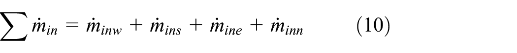
In forward flight, the flow field characteristics and droplet impingement characteristics of rotor blade vary with the different azimuth angles, so the unsteady method is needed in icing calculation. In this article, the rotation period is divided into several time steps. In each time step, the flow field, the droplet trajectory, and the ice growth rate of rotor blade in this time step are calculated. Finally, the ice growth rate in the rotation period is accumulated to calculate the icing thickness in a given time. The calculation process is shown in Figure 1.

Calculation process of rotor icing in forward flight.
Grid generation method
The whole flow field is simulated by the overlapping method based on the background grid including the blade grid.10–12 In this article, the geometry of background grid is rectangular and it can be generated by three-dimensional geometry method. The blade grid is a body fitted grid around the rotor blade. The pseudo three-dimensional method is used in the generation of blade grid, which simplifies the difficulty of grid generation. The pseudo three-dimensional grid generation method mainly includes the following steps: (1) according to the geometrical shape, the rotor blade is divided into several airfoils along the spanwise direction; (2) the airfoil grid is obtained by two-dimensional grid generation method; (3) the two-dimensional grids of each section are connected into a three-dimensional blade grid based on the rotor geometrical characteristics; and (4) the grids of blade root and tip are generated so that the blade grid is complete.
It can be seen that the blade grid generated by the pseudo three-dimensional method relies on the two-dimensional airfoil grid generation method, so the computational efficiency is high and the computing time and resources can be reduced. At the same time, the parameters of the three-dimensional grid such as orthogonality and near-wall grid size depend on the related parameters of airfoil grid, so it is beneficial to ensure the grid quality. Figure 2 shows the overlapping grids of Caradonna and Tung (C-T) rotor in this article. The O-H type blade grid has 150 radial × 66 normal × 100 span points (60 span points on the blade), and the background grid has 101 × 101 × 101 points. The first near-wall grid height is set to
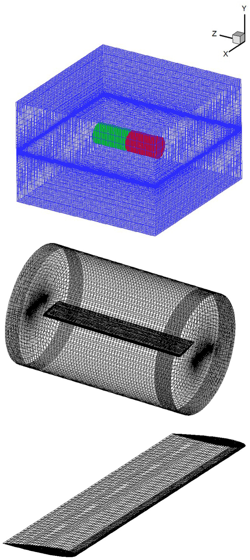
Overlapping grids used in this article.
For the flow field in forward flight, the blade grid is required to vary according to the rotor motion. In order to simplify the research, it is assumed that the rotor does not deform. In this article, the coordinate system is shown in Figure 2, in which Y-axis is the rotation axis and X-direction is the free flow direction. The rotor motion includes periodic rotation, pitching, and flapping. For the blade grid, the initial time coordinate

where
Air flow field calculation
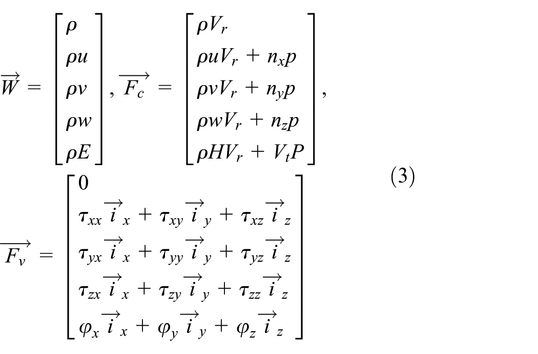
For the forward flight, the flow field is unsteady in either the ground coordinate system or the rotating coordinate system, so it is necessary to use the unsteady calculation method in the absolute coordinate system to simulate the whole flow field. The governing equations are defined in the ground coordinate system, and the absolute physical quantities are used as the parameters. The Navier–Stokes (N-S) equation in conservation integral form is established as follows14,15

where

where
In the solver, the cell-centered finite volume method is used to discretize N-S equation. A second-order central difference scheme is employed in convective fluxes computation and the artificial dissipative terms are added to reduce the numerical oscillation. 16 For the unsteady flow, the dual time-stepping method is used to solve the temporal discretization, and pseudo time derivative term is applied in the physical time derivative term. At the same time, local time stepping and implicit residual smoothing are adopted to accelerate convergence.17,18 The Spalart–Allmaras model 19 is applied to simulate turbulence, and its accuracy can meet the calculation requirements. 20
Droplet trajectory calculation
In this article, Eulerian model is used to calculate droplet trajectory. The supercooled droplets in the clouds are considered as continuous phase in Eulerian model. The mass and velocity distribution of droplets are obtained by solving the governing equations. Eulerian model has obvious advantages in the three-dimensional droplet trajectory calculation, and the model has been greatly developed in recent years. Based on the flow field results, the mass and momentum equations for droplet can be obtained as follows21–23

where
where

The droplet collection efficiency is the ratio between the amount of actual collected droplet and the maximum amount of droplet that may be collected, which is one of the important parameters in the icing research. The droplet collection efficiency based on Euler method is defined as
where
Ice accretion calculation
Three-dimensional ice accretion calculation is based on the flow field and droplet trajectory calculation results. By constructing the mass and energy conservation equation of surface liquid water, the mass of ice accretion and ice shapes of rotor blade are obtained. The effect of centrifugal force on icing process should be considered in the rotor icing calculation. The surface is divided into several control units as shown in Figure 3 and the mass and energy conservation equations of each control unit are listed as24,25

where


Surface control unit.
where
The motion of liquid water is influenced by external forces. In the rotating state, the liquid water is subjected to the combined action of aerodynamic shear stress and centrifugal force. The flow direction and distribution of liquid water are different from those in non-rotating state. The correlational research shows that liquid water flow and mass transfer are mainly affected by shear stress

The resultant force of centrifugal force and shear stress can be decomposed into components of East-West and North-South directions

Therefore, the following principles of liquid water flow distribution are adopted in this article

The ice accretion equations can be solved based on the calculation results of flow field and droplet trajectory. The calculation starts at the stagnation point, and because there is no water flow in, it is assumed that
Ice shape calculation
The mass flux of icing can be obtained by solving the ice accretion equations. Then the ice growth rate in each time step is calculated

In forward flight of rotor, the ice growth rate varies with time. The average ice growth rate of the rotation period can be calculated through integration of ice growth rate in each time step

where
The icing thickness is obtained by multiplying the average ice growth with the icing time, which can be expressed as
where
Method verification
Due to the lack of icing experiment in forward flight, the calculation methods of flow field, droplet trajectory, and icing model are verified. The results are compared with the experimental and literature results in order to prove the feasibility of the computational code.
Flow field verification
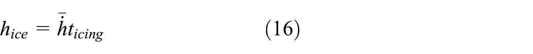
The flow characteristics of C-T rotor in non-lifting forward flight are calculated. The Mach number at the blade tip is
Pressure coefficient of rotor in forward flight.
Droplet trajectory verification
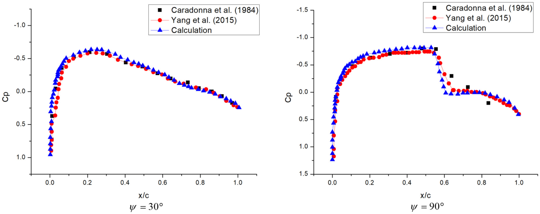
The droplet impingement characteristics are calculated to verify the correctness of method. A NACA0012 airfoil section is chosen here and the chord length is set to 1 m. The flow velocity is 138.88 m/s, the angle of attack is 5°, and the mean volume diameter (MVD) of droplet is 16 μm. 28 The size of the O-type grid around the airfoil is 200 radial × 66 normal. The calculated results of droplet volume fraction distribution and droplet collection efficiency are shown in Figures 5 and 6. It can be seen that one part of droplets impact on the leading edge, and the other part flow around the airfoil. By comparing the calculation results of droplet collection efficiency with the experimental results, it is found that the agreement is good. The droplet impingement ranges and magnitude of droplet collection efficiency are almost the same, which indicates the accuracy of Eulerian method used in this article.
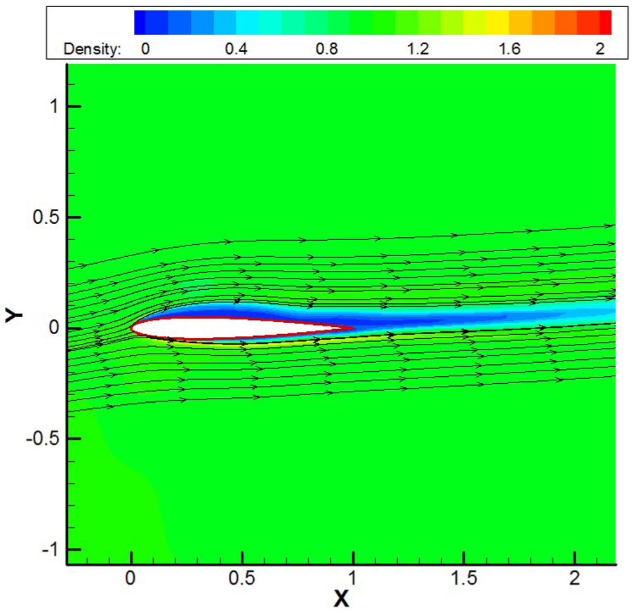
Distribution of liquid water content and droplet trajectories.

Comparison of droplet collection efficiency.
Rotor icing verification
The icing parameters of rotor under real condition are difficult to measure. The experimental environment on the ground of rotor icing is limited by the size of blade, and the experiment is usually carried out in cold environment. It is difficult to build the forward flight condition in cold environment, so the experimental results in hovering flight are selected to verify the numerical simulation method. Then the method is used to calculate the rotor icing in forward flight. The ice shapes of rotor blade in hovering flight under two conditions are simulated in this article. The calculation results are compared with the experimental and the ARISP results. 29 The blade airfoil is NACA0015, the chord is 0.15 m, and the blade radius is 1.24 m. The calculation conditions are shown in Table 1. The size of grids is the same as the grids of C-T rotor in Figure 2.
Calculation conditions.

MVD: mean volume diameter; LWC: liquid water content.
It can be seen from Figure 7 that the calculation results are in good agreement with the experimental results, and the predicted ice thickness and icing range are also predicted accurately. What’s more, the calculation results are more close to the experimental results than the ARISP icing model. The ARISP model is developed based on LEWICE software and the ice shape of airfoil is calculated. However, the ice shape of three-dimensional rotor is different from two-dimensional airfoil because of rotation effect. Therefore, the icing model in this article can simulate the rotor icing, and it has a better accuracy.

Comparison of rotor blade ice shape.
Analysis of rotor icing in forward flight
The C-T rotor is applied to calculate the rotor icing in forward flight. The C-T rotor is widely used in the rotor research. The rotor has two untapered and untwisted blades with an airfoil of NACA0012, and the aspect ratio is 6. The droplet trajectory and ice accretion of rotor are calculated in lifting forward flight. The calculation results of droplet impingement characteristics and icing characteristics at typical azimuth angles are given, and the icing law in forward flight is analyzed.
The icing conditions for lifting rotor in forward flight are chosen based on FAR-29 Appendix C, which are listed below: Mach number at the blade tip
The grids are shown in Figure 2. The rotation period is divided into 120 time steps, and each time step requires 3000 iterations in flow field and droplet trajectory calculation, respectively. At least three complete cycles are used to establish the periodicity of flow field. The computing platform is Inter(R) Core(TM) i7-4790K CPU processor with a clock speed of 4.00 GHz and the memory is 16 GB. Each step of flow field and droplet trajectory calculation takes nearly 5 h. The ice accretion is calculated on the rotor surface, so it takes only a few minutes which can be ignored.
Droplet collection efficiency analysis
Figure 8 shows the droplet collection efficiency of rotor at different azimuth angles. Figure 9 shows the distribution of droplet collection efficiency on the

Distribution of droplet collection efficiency at different azimuth angles.

Curve of droplet collection efficiency at different azimuth angles.
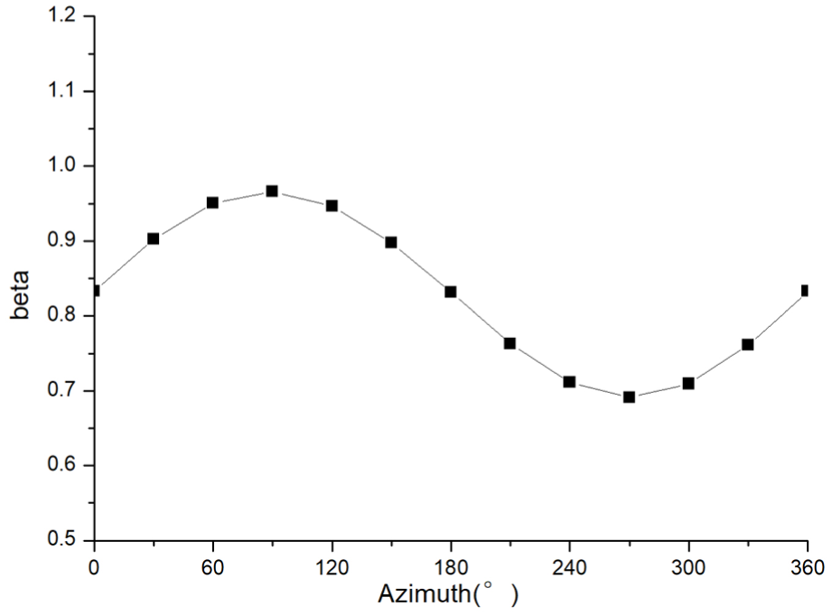
Curve of maximum droplet collection efficiency.
The distribution of droplet collection efficiency changes with pitch angle. When azimuth angle is 90°, the pitch angle is the smallest. The droplet impingement zone is closer to the upper surface and the range of droplet collection efficiency is minimum. When azimuth angle is 270°, the pitch angle is the largest. The droplets mainly impact on the lower surface, and the range of droplet collection efficiency is the largest.
The maximum value of droplet collection efficiency is about 1, and the minimum is nearly 0.7. This is because the local velocity of blade leading edge varies with the azimuth angle in forward flight. When the azimuth angle is 90°, the local velocity of blade is the largest, and the droplet impact velocity also increases, so the droplet collection efficiency is the largest according to the calculation formula. When the azimuth angle is 270°, the leading edge has the smallest local velocity, so the droplet collection efficiency is the smallest. It can be seen that the variations of local velocity at different azimuth angles affect droplet collection efficiency. When the blade rotates in the windward half circle (
Icing characteristics analysis
Figure 11 shows the ice growth rate of rotor at different azimuth angles. Figure 12 shows the distribution of ice growth rate on the

Distribution of ice growth rate at different azimuth angles.

Curve of ice growth rate at different azimuth angles.

Curve of maximum ice growth rate.
It can be seen that with the change of azimuth angle, the ice growth rate and icing range of blade change greatly. When the azimuth angle is 90°, the ice growth rate is the largest, but the icing range is the smallest. When the azimuth angle is 270°, the ice growth rate is the smallest, while the icing range is the largest. The variation trend of the maximum icing rate curve is similar to droplet collection efficiency, but the details are different. Icing is mainly affected by droplets impacted on the surface, so the icing characteristics are similar to the droplet impingement characteristics. However, icing is not only affected by the impacted droplets, but also by air flow. At different azimuth angles, the air flow field changes greatly, so the variation trend is slightly different.
The average ice growth rate in the rotation period is different from that at each step. The icing range is affected by the icing characteristics at each azimuth angle, so the icing range is the same as the maximum icing range in the rotation period. The red line in Figure 13 represents the maximum value of average ice growth rate, and it can be seen that the value is slightly smaller than the values at the azimuth angles of 0° and 180°.
The calculation results show that the variations of local velocity have a great influence on rotor icing. The droplet collection efficiency and ice growth rate of the advancing blade are larger, while that of the retreating blade are smaller. Therefore, the unsteady motion of blade must be taken into account in rotor icing calculation.
Finally, the three-dimensional ice shape is shown in Figure 14 and the ice shapes of different blade sections in forward flight are given in Figure 15. The icing occurs mainly at the leading edge of blade. As the spanwise distance increases, the icing thickness becomes thicker and the icing range is larger.

Three-dimensional ice shape of rotor blade.

Ice shapes at different rotor sections.
Influence of time step on rotor icing
The influence of time step on the ice shape is studied. The
The effect of different time steps on icing results.

Conclusion
In this article, a numerical simulation method of three-dimensional rotor icing in forward flight is presented. The unsteady calculation method is adopted: the overlapping grids are used and the blade grid is generated by pseudo three-dimensional method. The flow field is calculated using N-S equations in the ground coordinate system and the droplet trajectory is calculated by Eulerian model. Three-dimensional surface ice accretion model is applied to simulate the rotor icing, and the influence of centrifugal force on the ice shape is considered in the model. The ice growth rate at each azimuth angle in a rotation period is obtained, and the icing shape can be calculated by the average ice growth rate. Through icing simulation results, the droplet impingement characteristics, and icing characteristics of the rotor in forward flight are obtained. Further conclusions are drawn as follows:
The three-dimensional rotor icing in forward flight can be simulated using the numerical simulation method proposed in this article. Icing occurs mainly at the leading edge of blade, and the ice shapes of the different sections are not the same.
The forward flight and pitch motion of blade have a great influence on the icing process. The variations of local velocity and pitch angle will lead to the change of the magnitude and distribution of droplet collection efficiency and ice growth rate obviously. The values of droplet collection efficiency and ice growth rate are larger in the windward half circle (
The average ice growth rate in forward flight is significantly different from that at different azimuth angles. The unsteady method is needed in the calculation process, and the time step will affect the calculation accuracy.
Footnotes
Handling Editor: Mustafa Canakci
Declaration of conflicting interests
The author(s) declared no potential conflicts of interest with respect to the research, authorship, and/or publication of this article.
Funding
The author(s) disclosed receipt of the following financial support for the research, authorship, and/or publication of this article: This work was supported by the National Basic Research Program of China (“973” Project) under grant no. 2015CB755800 and the National Natural Science Foundation of China under grant no. 11402114.