
Abstract
In present, the drilling industry have to face the reality of low oil and gas prices, fully mechanical vertical drilling tool is likely to become the best choice for vertical drilling in the future. Without electric measurement and control system, the mechanical vertical drilling tool has a mechanically stable platform with gravity sensitivity. The stable platform included an eccentric block which is not only sensitive to gravity but also severely affected by torsional vibration. In this article, we reveal the dynamics of eccentric block under the effect of torsional vibration, which is the key element of the well deviation control accuracy in mechanical vertical drilling tool. The dynamic model of eccentric block is established using Lagrangian equation and Coulomb friction, and the law of dynamic characteristics under the effect of different amplitudes and period of torsional vibration is found. The results show that, with the deviation angle and eccentric torsion moment of eccentric block is increased, the resistance to torsional vibration increases. While the frequency of torsional vibration decreases, a subordinate period gradually appears after the rotation speed value of ω is less than 1 rad/s, the torsional vibration with large amplitude and high frequency is detrimental to the stability of the eccentric block. In addition, the largest Lyapunov exponent is estimated using the time series of simulation, the dynamics of eccentric block under the effect of torsional vibration can be switched four types, and the maximum and minimum values of largest Lyapunov exponent are 3.99 × 10⁻² and −2.98 × 10⁻², which means with the state of torsional vibration changes and the response of eccentric block would be transformed to chaos.
Keywords
Introduction
Inclining prevention, while fast drilling in high and steep structures, is a challenge in oil and gas drilling engineering. Automatic vertical drilling technology is advanced in vertical well operation based on downhole vertical drilling tools, which has been successfully applied to well trajectory control in blocks with high and steep formations. Unlike traditional inclining prevention technology, such as pendulum assembly and packed hole assembly, active deviation control is realized by automatic vertical drilling technology, the well deviation could be kept at less than 1°, the drill pipe friction is reduced obviously, the efficient of drilling is significantly improved, and the drilling cost is effectively reduced.1,2
The vertical drilling tool (VDT) is designed for the first time in KTB borehole-Germany’s superdeep drilling program. 3 After three decades development, the VDT with electronic components has been widely and commercially applied, such as Power-V, 4 SDD, 5 VDS, 6 the well quality, and drilling efficiency are further improved.
The operation and maintenance costs of electric-controlled VDT were high due to its high-cost and vibration-sensitive electronics. However, the drilling industry have to face the reality of low oil and gas prices in present, drilling costs needed to be reduced further. 7 The development of fully mechanical vertical drilling tool (MVDT) was perfectly adapted to the current economic situation. MVDT has the following advantages: (a) low costs due to its fully mechanical structure, (b) high temperature resistance, (c) high suitability and reliability without electric components, and (d) high bearing capacity for larger weight on bit (WOB) and rate of penetration (ROP). Thus, MVDT will become an optimal choice for vertical drilling in the near future.
The MVDT can rotate with drill bit and drillstring during drilling process. Figure 1 shows the working principle. There are three main components in the tool for the mechanical control system. (a) Retractable piston—apply force of inclination correction through pushout to borehole wall. (b) Plate valve—direct the mud to apply pushing force to piston at the higher side of borehole. (c) Eccentric block—locate the mud control valve through holding itself on lower side of borehole due to gravity. 7 The eccentric block is mounted on outer cylinder using bearings, by which the eccentric block could freely rotate around its axle. An upper plate valve is rigid connected with the eccentric block, and there is an opening opposite to the eccentric block. Under the upper plate valve, there is another piece of lower plate valve with three mud flow channels rotating synchronously with bottom hole assembly (BHA). 8
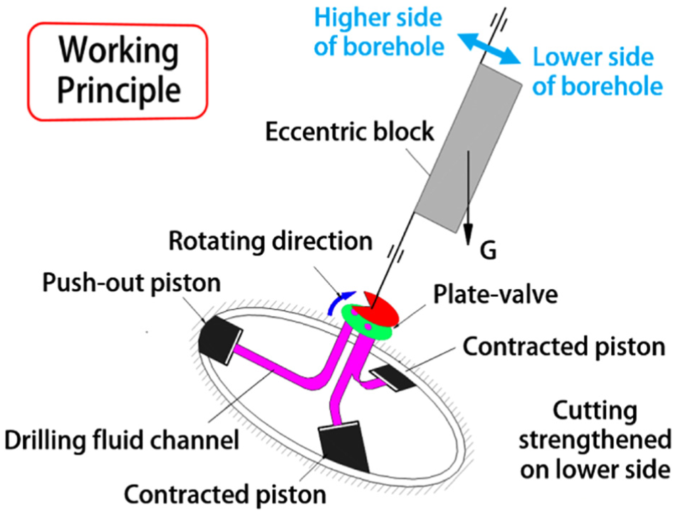
Schematic of working principle of MVDT.
When the inclination reaches a certain value, the eccentric block will rotate to the lower side of borehole under its eccentric torsion moment due to gravity, the opening of upper plate is rotated to the higher side of borehole, the mud flow channel on the higher side of borehole is unfolded, and then the position is pushed out. In the drilling process, the lower plate valve rotates with BHA, the three mud flow channels alternately connected, then the pistons will be pushed out on the borehole wall by turns under the pressure difference of mud between inner tool and annulus, which is approximately equal to pressure-drop of bit nozzles. This process will produce a continuous lateral force from the high side to the low side of the direction on the drill bit, thus the well trajectory will gradually restore to vertical.
During vertical drilling process, field observations based on downhole and surface vibration measurements have indicated that the drillstring and BHA exhibit severe vibration,9,10 which is characterized by (a) sticking phases where the bit stops and (b) slipping phases where the angular velocity of the tool increases up to two times of the imposed angular velocity. This inhomogeneity rotation speed, also called stick-slip, was first founded by Cunningham 11 through analyzing data of downhole measurement as early as 1968, and the research field of its mechanism was initiated by Belokobyl’skii and Prokopov 12 in 1982, by whom proposed that this inhomogeneous phenomenon was caused by the non-linear friction of the negative damping generated on the rupture surface when the drill bit broke rock. Since then, a lot of researchers concluded that the mechanism of drillstring self-excited vibration is mainly caused by drill negative damping torque13,14 and the non-linear friction between drillstring and borehole wall, and until nowadays, it still attracts great interests of researchers as a very common phenomenon due to its great dangers and inevitability.15–17 Torsional vibration greatly influences the performance of bottom drilling tools, and the detriment of it must be taken seriously.18–21
For MVDT, especially using the model of push-the-bit, its retractable pistons constantly push against the borehole wall and generate cycle torque and drag to the BHA, which leads the movement of MVDT to more severely torsional vibration. As a result, the torsional vibration presents obvious feature of non-linear kinetics and exerts a huge impact on inclination preventing behavior of MVDT. Without electric measurement and control system, the performance of deviation control of MVDT is directly determined by the dynamics of eccentric block, which is severely impacted by torsional vibration. Once the torsional vibration of BHA occurs, the rotation speed of the lower plate valve will be vibrating along with the BHA, then the dynamics of eccentric block must be altered simultaneously through the interaction between the upper and lower plate valve by (a) the friction coefficient switches between static and dynamic; (b) the instantaneous power of plate friction changes over time. Therefore, the behavior of eccentric block must be presented complicated dynamics, by which the inclination preventing precision of MVDT is adversely affected. The dynamics of eccentric block under the effect of torsional vibration must be further studied to discover its effect law, which is a matter of crucial and imperative significance for optimizing and obtaining advanced MVDT with high performance.
Mathematical model
Mechanical structure of stable platform with gravity sensitivity
The mechanical model of stable platform with gravity sensitivity of MVDT is shown in Figure 2. There is an upper joint and a lower plate valve on each side of the outer cylinder, respectively, connecting with the upper drill pipe and the piston chamber. In the inner space of the out cylinder, an eccentric block is mounted by bearings between the upper flange and lower flange, the eccentric block can freely rotate to the lower side of the borehole due to gravity, while the outer cylinder, upper joint, upper flange, lower flange, support ring, and lower plate valve synchronously rotate with the upper drill pipe. On the lower side of the eccentric block, an upper plate valve with its spool opening opposite to the eccentric block is assembled by key joint, thus the upper plate valve could rotate together with the eccentric block to control the piston pushout. Under the action of the positive force formed by inner and outer pressure difference of mud, the upper plate valve can keep contacting closely with the lower plate valve all the time.
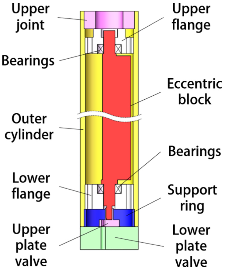
Schematic of mechanical structure of gravity-sensitive stable platform.
Dynamic model of eccentric block
The cross section drawing of eccentric block is designed as sector appearance, as shown in Figure 3 because of this axial symmetry shape, and the coordinate of the mass center is set as (0, YC), then YC can be calculated according to its physics principle

wherein

Cross section drawing of eccentric block.
Assume that the deviation angle of borehole is
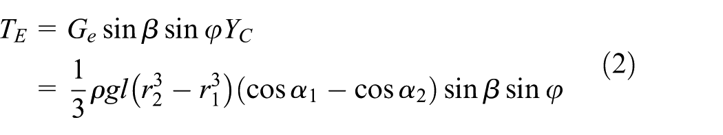
wherein ρ and l are, respectively, referring to the density and the length of eccentric block; and g is the gravitational acceleration. When

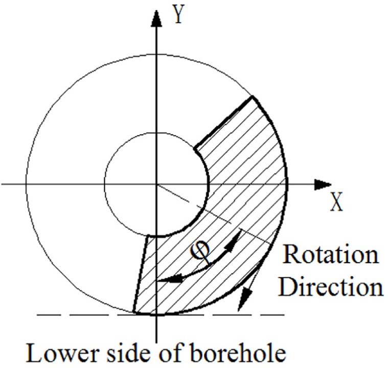
Rotation schematic of eccentric block.
In order to ensure that the eccentric block can hold its position on lower side of borehole, as shown in Figure 5, the torque equation must abide by

wherein

Principle of stable platform with gravity sensitivity.
Define

Figure 6 shows the contact surface schematic of upper plate valve, with d, D,

wherein

wherein P is pressure difference of mud between inner tool and annulus.

Contact surface schematic of upper plate valve.
Due to the special characteristic of bearings, the friction torque

Mathematical model of torsional vibration
The rotary drilling structure consists essentially of a rig, drillstrings, and BHA. The BHA in this analysis refers to the lower part of the drillstring, which includes the drill collars, stabilizers, MVDT, and the drill bit. We established the simplified drillstring torsional vibration model as shown in Figure 8. Some assumptions are made as following: (a) the drillstring is homogeneous along its entire length and simply considered as a single linear torsional spring with stiffness coefficient K.
22
The borehole and the drillstring are both vertical and straight, no lateral hit motion presents; (b) the boundary conditions applied by the rig to the top drive of the drillstring correspond to a constant angular velocity Ω0; (c) the influence of drilling mud is neglected; (d) the bottom surface of borehole is composed of a large number of asperities with the shape of ellipsoidal, the height distribution of the asperities is uniform, and the contacting asperities have the same ovality ratio; (e) each of asperities follows the Hertz theory for elliptical contacts, by which the torsional vibration of BHA can be seen as a kind of compelling vibration excited by an additional harmonic vibrating motion of the borehole rock and takes the form

(a) Compelling vibration excited by the wave shape of the bottom and (b) simplified model of the drilling system.
The BHA motion as well as the forces acting on the BHA can in principle calculated by a mechanical model show in Figure 7(b), and we only consider the discrete model of the drilling system characterized by one degree of freedom

wherein

wherein C is equivalent viscous damping coefficient of BHA, and

Then, the general solution of the rotation motion equation can be solved by the numerical solution method 27

wherein

Then, the angular velocity of BHA Ω can be described as

Friction model
As a friction model widely used in engineering, the classic Coulomb model is selected to describe the friction coefficient change with slid velocity in this article. Considering the difficulty in using the discontinuous friction model during simulation, in order to obtain convergence results, the curve of Coulomb model is modified to a kind of continuous curve with the characteristic of gradually changing,28,29 as shown in Figure 8.
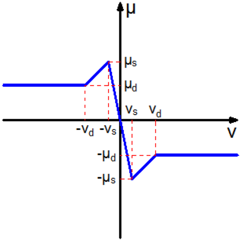
Friction coefficients with different slid velocities.
During the mechanical model construction, the pressure difference between upper and lower plate valve

wherein

wherein
Parameters determination used in simulation
Parameters used in simulation
The parameters used in simulation are shown in Table 1, including design parameters according to structure design of MVDT, measured parameters according to experimental measurement, and fitting parameters fixed by field drilling data in sections “Field measurement data analysis” and “Parameters determination for torsional vibration” as follows. The drilling process and mechanical processing of MVDT are taken into consideration to determine the design parameters of the eccentric block and the plate valve, the
Parameters used in simulation.

Field measurement data analysis
Field BHA data directly reflect the motion of BHA during drilling, it can be measured and stored by measuring system installed in non-magnetic collar near the drill bit, which is shown in Figure 9. In this measuring system, downhole memories and sensors are installed, in which included a three-axis magnetometers, a three-axis accelerometers, and an angular speed sensor (gyroscope), and the sampling frequency is 100 Hz. The calculation of angular speed of BHA was presented in previous work and no more detailed description is presented here. 21 One section of downhole angular speed data of BHA are shown in Figure 10. Before data analysis, three kinds of torsional vibration state is defined as follows

wherein

Field drilling data measuring system installed near the bit.

Downhole angular speed of field drilling data.
The measurement results show that, at the beginning, the torsional vibration of BHA is switched frequently between the states of mild, moderate, and severe, but gradually the amplitude of drilling torsional vibration generally increased due to the penetration deepens into difficult formation. Approximately at 1200 and 1500 s, the angular speed
Parameters determination for torsional vibration
As shown in Figure 10, the region that emphasized by red rectangle listed from No. 1, No. 2 to No. 3, respectively, refers to three kinds of typical stick-slip, namely, mild torsional vibration, moderate torsional vibration, and severe torsional vibration. For excluding the interference of random factor, these field measured data need to deal with curve fitting using the torsional vibration model of BHA shown in equation (14), the fitting results with 95% confidence bounds of these data are as follows

wherein

Fixing curves of three typical section parameters corresponding to Figure 9: (a) mild torsional vibration refers to No. 1 region, (b) moderate torsional vibration refers to No. 2 region, and (c) severe torsional vibration refers to No. 3 region.
Goodness of fit compared to measured data.

SSE: sum of squares due to error; RMSE: root mean squared error.
To facilitate an effective analysis of the influence of torsional vibration, the angular speed of BHA for simulation could approximate to

where
Methods
Lagrangian approach
The dynamic equation of the gravity sensing platform is established by the combined use of the conservation of momentum and the Lagrangian approach, by which the statics, kinematics, and dynamics of the system can be analyzed. The Lagrange equation can be acquired by expressing a general dynamic equation of a non-free particle system using generalized coordinates, and on this basis, a motion differential equation of a general mechanical system can be obtained by Lagrangian multiplier method. We set the generalized coordinates of a rigid body

wherein E is kinetic energy of system, q is an array of generalized coordinates, Q is an array of generalized force,
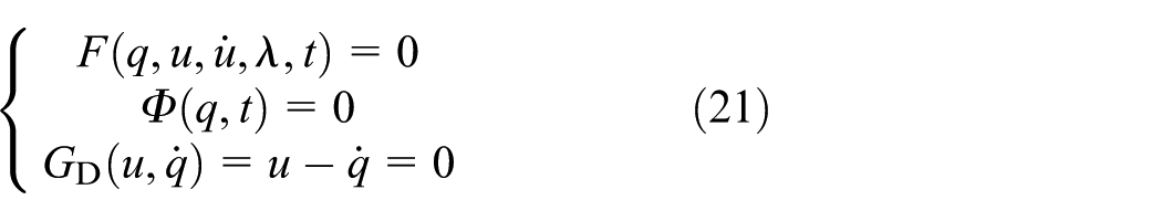
wherein λ is an array of constraint force and applied force, Φ is an array of algebraic equation describing constraints, and F is the dynamic differential equation of the system. We define a state vector

Equation (22) can be solved step by step through (a) prediction using Taylor series and Gear integral polynomial, (b) transforming the solve of non-linear equations into approximately solve linear equations using iteration correction, (c) integral error analysis, and (d) optimization of the integral step and order of integral polynomial, then the curves of displacement, speed, acceleration, applied forces can be obtained. 31
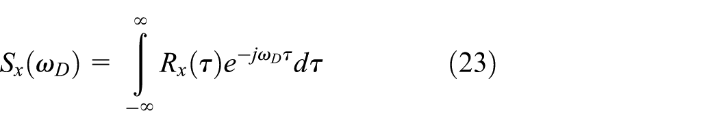
Power spectral-density analysis
Power spectral-density (PSD) is one of the most important presentation form of stochastic signal, and the power density spectrum has been obtained using Welch Power method. According to Wiener–Khinchin theorem, auto-PSD of the steady stochastic signal and its auto-correlation function
Nonlinear analysis of simulation time series
Phase-space reconstruction
The dynamics of the time series

wherein τ is the delay time. Cao’s 33 method computes E1 and E2 for the data set of dimension 1 up to a dimension of Dd, which is the largest embedding dimension, used for calculation. E1 and E2 are defined as follows
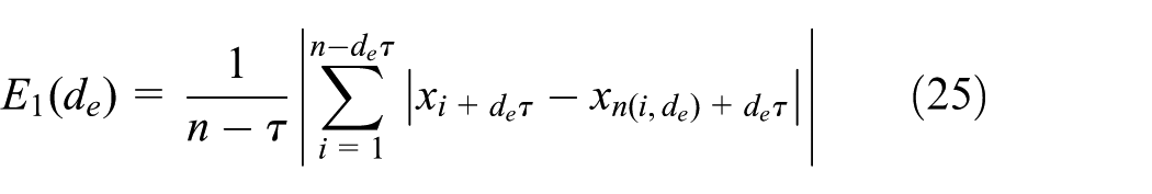

wherein de is the embedding dimension; N is the number of data points; τ is the embedding delay;
Largest Lyapunov exponent
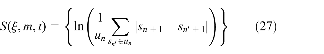
The basic characteristics of chaotic motion are that the movement is extremely sensitive to initial conditions, two very close initial values resulting in orbit over time by separating exponentially, Lyapunov exponent35,36 that describes the amount of this phenomenon. We use the algorithm of Rosenstein et al. to calculate the Largest Lyapunov exponent (LLE). Consider the representation of the time series data as a trajectory in the embedding space and assume that observe a very close return
Results
Dynamics of eccentric block without torsional vibration
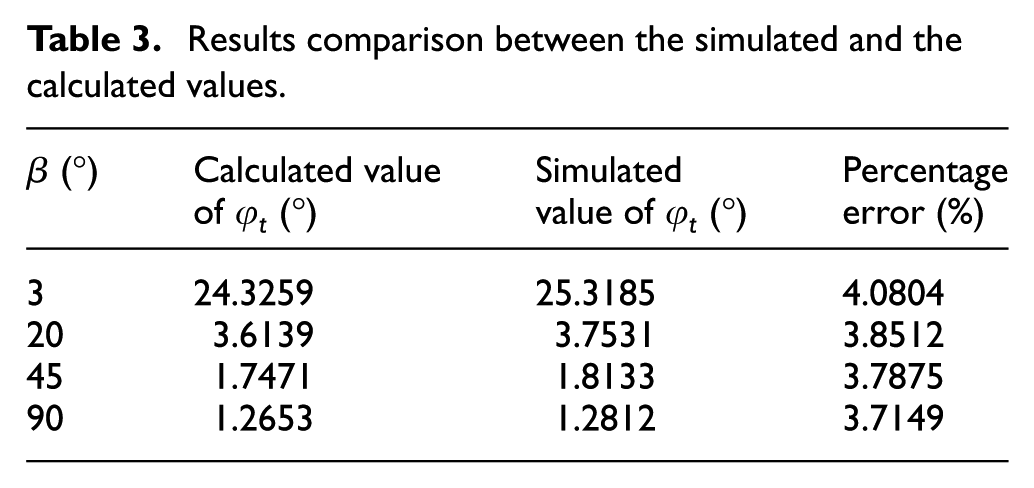
Before analysis the dynamics of eccentric block under the effect of torsional vibration, the dynamics of eccentric block without torsional vibration must be simulated first, and results under different deviation angles from 3° to 90° using the same constant angular speed Ω = 10 rad/s are shown in Figure 12. Because the Lagrangian approach is selected as the simulated method, its numerical solution must be different from analytical solution calculated by equation (8), the results comparison between the simulated and the calculated values of deflection angle are shown in Table 3. When the deviation angle increased from 3° to 90°, the simulated values of
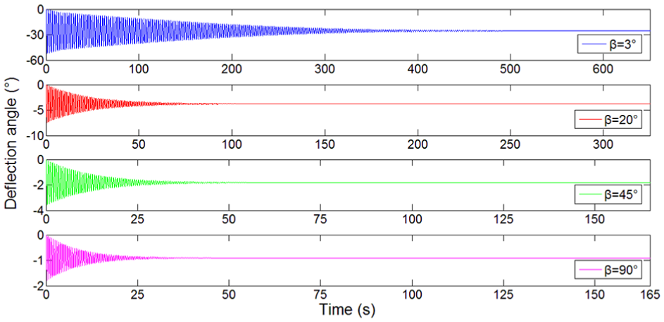
Simulation results under different deviation angles when the angular speed was 10 rad/s.
Results comparison between the simulated and the calculated values.
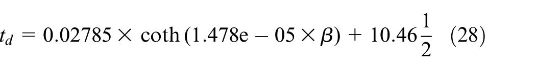
Under the force of friction, the motion of eccentric block is a type of damped pendulum action as shown in Figure 12. Here, we define a steady state, after the vibration amplitude damping to less than 0.1°, the steady state of eccentric block starts going on. The time required for the pendulum action damped into the steady state, we defined it as damping time td. Values of td under different deviation angles are shown in Figure 13. As β increases from 3° to 90°, the value of td sharply reduced from 638.5 to 25.8 s and the maximum deflection angle significantly increases from −58.2° to −1.79°, due to the larger stability acquired by larger


Damping time and maximum deflection angle under different deviation angles.
Dynamics of eccentric block affected by vibratory amplitude
The impact of different vibratory amplitudes on deflection behavior of eccentric block when β is 3° as shown in Figure 14. After torsional vibration occurs, the swing amplitude of deflection angle no longer presenting as single attenuation wave, and the swing of eccentric block gradually transforms into a kind of pendulum motion with a constant period stimulated by the additional harmonic wave induced by borehole bottom. In addition, the swing of eccentric block is independent of the amplitude of torsional vibration. As shown in Figure 14, it is obvious that the larger intensity of torsional vibration, the larger swing amplitude of deflection angle. As the value of B increases from 3, 6 to 10, the relevant swing amplitude of deflection angle is, respectively, 2.5°, 14.4°, and 44.9°, and the time spent before the periodic pendulum motion reduces from about 168, 32 to 20 s. However, the torsional vibration is wild or severe, and the pendulum motion of eccentric block swings around a constant intermediate value of about 24.2° all the time. It is slightly smaller than simulated value of

Impact of different vibratory amplitudes on deflection behavior of eccentric block with deviation angle of 3°.
Figure 15 is the PSD analysis of the impact of different vibratory amplitudes on deflection behavior of eccentric block under the deviation angle of 3°. Each curve showed the same characteristics in the high frequency, because the high-frequency component of the spectrum analysis mainly comes from the random noise, which is neglected in this article. When the BHA rotates without torsional vibration, there is only one significant peak at point A with a characteristic frequency of 9.5 × 10⁻³π rad as shown in Figure 15, which is consistent with the swinging deflection angle of eccentric block. The simple damping motion of the angle will gradually approach to a constant value. After torsional vibration occurs, it is obvious that the phenomenon of fractal appears. There are many peaks along the PSD curves, when the intensity of torsional vibration increases, the general power of characteristic frequencies grows obviously and the number of significant peaks increases as the distribution of effective peaks lasts wider along normalized frequency axis. With the increase in the value of amplitude B gradually from 0, 3, 6 to 10, the number of significant peaks of each curve is 2, 3, 6, and 6, and the maximum power of characteristic peak is, respectively, 13.1, 1.24, 14.17, and 24.1 dB at points A, B, C, and D in Figure 15. The impact of vibratory amplitude on deflection behavior can be seen as a gradual change process along with the amplitude growth. The single damping motion without torsional vibration tends to gradually transform to a periodic motion with the increase in intensity of torsional vibration.

PSD analysis of the impact of different vibratory amplitudes on deflection behavior of eccentric block under β of 3°.
Dynamics of eccentric block affected by vibratory period
On basis of analysis above, when the value of vibratory amplitude is 10, the intensity of pendulum motion of eccentric block will be the largest, and will fully transform the periodic motion in short time, thus the severe torsional vibration is selected to research the impact of different vibratory amplitudes on deflection behavior of eccentric block, as shown in Figure 16, which are the simulation results acquired under the deviation angle β is 12°. Under this circumstance, a larger eccentric torque can provide a better stability of eccentric block and obtain curves with smaller amplitude. When the value of ω increases, the frequency of vibration becomes high, the curve of swing motion of eccentric block tends to transform to a sine-shape wave, and the transition time before steady period motion turns longer. When ω is 0.5 and 1, respectively, there is another subordinate period in one cycle of the curve line. During one subordinate period, the swing motion of eccentric block is around the deflection angle of 6.25°, the number of peaks in one subordinate period is 6 and 3, respectively, as ω is 0.5 and 1, which is depended on the frequency of the excited wave of borehole bottom. After the value of ω increases larger than 2, the subordinate period disappeared while the amplitude of vibration turns larger. On the scale of one period, the calculated value is 5.95 according to equation (8), set the percentage error is 4, and the simulated value of

Impact of different vibratory periods on deflection behavior of eccentric block under β of 12°.
The PSD analysis of these four time series are shown in Figure 17, the difference between them is much larger when compared with Figure 15, which means the impact of vibratory period on deflection behavior is larger than the impact of different vibratory periods. When the value of ω gradually increases from 0.5, 1, 2 to 3, the power value at low normalized frequency presents the phenomenon that first decreases and then increases, while at high normalized frequency presents the different phenomenon that monotonically decreases. It is obvious that with the increase in ω, the peak distribution of characteristic frequencies becomes more and wider due to the existence of subordinate period mentioned above. After the subordinate period disappeared when ω is 2 and 3, at 0.02 πrad along normalized frequency, the power of characteristic peak increases to the maximum value, respectively, is 15.62 and 22.76 dB at point C and D; the number of peaks decreases obviously and the peaks get closer with each other as well as the power grows significantly, which means the difference value between the maximum amplitude and second major amplitude of deflection angle gradually decreases to zero. Thus, an inference can be made here, if the value of ω is large enough, the swing of eccentric block can be eventually involved to a steady pendulum motion with a short period.

Power-density spectrum analysis of the impact of different vibratory periods on deflection behavior of eccentric block under β of 12°.
Classification of eccentric block dynamics
Through comparative analysis of simulating results, the defection curve of eccentric block under the impact of torsional vibration can be generalized into four typical examples as shown in Figure 18. They can be represented as follows: (a) the work of eccentric torque on eccentric block is less than the work of plate friction, the eccentric block rotates around its axle, and the deflection angle is reciprocated between −90° and 90°. (b) The work of eccentric torque is larger than the friction work, the eccentric block does not rotate anymore and swings around its critical angle with a steady period, which can be seen as a kind of quasi-sine pendulum motion. (c) The motion of eccentric block is still swinging around a critical angle, but the motion curve is no longer along a curve like a single sine shape during one period, while the shape of a period curve is superimposed by two or more sine curves. (d) With the eccentric torque increasing further, if the stability of eccentric block grows enough, a significant subordinate period will appear in one period of motion curve. These four typical motion curves are expressed, respectively, by the position of mass center along X-axis, and the angular speed is shown in Figure 19; in them, Figure 19(a) shows the steady state of the curve shown in Figure 18 for a better exhibition, and other three figures show the overall process including transition section. If the eccentric block rotates around its axle, the motion of it is a kind of varying accelerated motion under the action of eccentric torque and friction torque, the angular speed will accelerate to a relative high level and the MVDT loses the deviation correction ability at this time. When the quasi-sine pendulum motion occurs, the shape of angular speed curve along X-axis position is close to circular, which presents the quasi-sine pendulum motion. With the single sine pendulum motion disappearing, the circular shape will be fractal to two or more ellipses with different orbits. After the significant subordinate period occurs, the shape of angular speed curve along the X-axis position becomes irregular, and as the ratio of subordinate period in one period increases, the irregularity increases.

Four kinds of deflection behavior expressed by time as X-axis and deflection angle as Y-axis.

Four kinds of deflection behavior by position as X-axis and angular speed as Y-axis.
Nonlinear analysis of simulation time series
A result can be obtained through the above analysis that the

3D surface of LLE affected by amplitude of torsional vibration.

3D surface of LLE affected by period of torsional vibration.
Discussion and conclusion
Due to the working principle of MVDT, the upper plate valve and the eccentric block are rigid connected and the dynamics of eccentric block presents obvious non-linear behavior under the effect of torsional vibration, by which the control precision and inclining preventing performance of MVDT are directly determined. The effect mechanism can be generalized as follows:
Both amplitude and period of torsional vibration impact the control response behavior of MVDT, with the
With the increase in the amplitude of torsional vibration, the swing amplitude of deflection angle increases. While the frequency of torsional vibration decreases, a subordinate period gradually appears after the value of ω is less than 1. Once the torsional vibration occurs, the average deflection angle in one periodic motion is slightly smaller than the deflection angle without torsional vibration, and transition time is less before entering the steady periodic state. However, a torsional vibration with large amplitude and fast frequency is detrimental to the stability of the eccentric block. If the torsional vibration is controllable, then small amplitude and slow frequency are the ideal state for acquiring a better response of eccentric block.
Through analyzing more than 30 groups of simulation results, the state of torsional vibration is that the response of eccentric block can be generalized in four typical motions, which are rotate motion, quasi-sine pendulum motion, swing motion without subordinate period, and swing motion with subordinate period. When
The LLE of time series of simulation results are calculated, and the non-linear analysis is carried out. The maximum and minimum values of LLE are 3.99 × 10⁻² and −2.98 × 10⁻², which means the response of eccentric block would be transformed to chaos with the state of torsional vibration changing, especially in spaces of
Based on above researches, a suggestion for engineering can be given, just taking the ideal uniform rotation of BHA into consideration is inadequate during the design of MVDT, the deviation control performance of the eccentric block must be tested and evaluated under the effect of torsional vibration. In this article, some laws of the dynamics of eccentric block under the torsional vibration are explored, but there is no clear influence law among LLE,
Footnotes
Appendix 1
Handling Editor: Elsa de Sa Caetano
Declaration of conflicting interests
The author(s) declared no potential conflicts of interest with respect to the research, authorship, and/or publication of this article.
Funding
The author(s) disclosed receipt of the following financial support for the research, authorship, and/or publication of this article: This work was supported by Beijing Natural Science Foundation (3174054), Natural Science Foundation of China (51704264), National Key R&D Program of China (2016YFE0202200), and Special scientific research fund for public welfare industry of ministry of land and resources of the People’s Republic of China (No. 201411054).