
Abstract
The interval finite element method based on the element-by-element technique is proved to be a rigorous and efficient method for considering interval uncertainties. The structural internal force of the same accuracy as the interval response displacement can be obtained by combining the variational method and the Lagrange multiplier method. However, the increase of the Lagrange multiplier reduces the efficiency of solving the equation, especially for a large truss system. In addition, the method is mostly used to analyse truss system, and the applications in plane problems are still rare. In this article, an improved method involving modification of the Lagrange multiplier interval equations is proposed to calculate interval displacements and interval internal forces at the same time. In this proposed method, the increase of the unknown Lagrange interval does not affect the solution of the equations. For plane problems, a new method for solving the stress interval of the element is proposed. This proposed method can effectively reduce the expansion of the stress interval of the element. Finally, the correctness and rationality of the proposed method are verified by numerical examples.
Keywords
Introduction
By combining the interval analysis method 1 with the finite element method, a new method for interval uncertainties, the interval finite element method,2,3 has been proposed. The main idea of the interval finite element method is to study the influence of the structural system parameters on the structural displacement and stress by considering the structural parameters as interval variables; its core content is to solve the interval governing equations. 4 Based on the monotonicity of the function, the combination monotone method was proposed by Rao and Berke. 2 However, this form of monotonicity is not always satisfied, and with more uncertain parameters, the calculation of this method is more complicated. A perturbation approach of the interval finite element method based on the perturbation theory was proposed by Qiu and Elishakoff 5 and Wang et al.; 6 however, their method can solve only small perturbation problems. Subsequently, a sub-interval perturbation method for large perturbation cases was proposed; 5 however, although the increase of the sub-interval improves the accuracy of the results, it also requires a large amount of calculation. The interval finite element method has a wide application prospect in engineering, but the interval extension caused by the interval correlation problem restricts the application of the method. Rump 7 proposed an interval iteration method based on Brouwer’s fixed-point theorem which has been shown to be efficient and accurate for solving linear interval equations. But, it may result in meaninglessly wide and even catastrophic results without dependency consideration. In the work of Muhanna et al.,8–10 based on the element-by-element (EBE) technique, the structural stiffness matrix is assembled, and the correlation problem caused by element stiffness coupling is fully considered by the interval factor separation method. The EBE-based interval finite element method was also extended to calculate the envelope frequency response functions with uncertain parameters by Yaowen et al.,11,12 and the results indicated the effectiveness of the EBE model to frame structures. To obtain the high-precision axial force of a truss, a Lagrange multiplier method was proposed by Muhanna et al., 9 the method provides the same accuracy axial force of truss as the interval displacement. However, the increased number of unknown quantities decreases the effectiveness of the method, especially for a large truss system. So far, the interval finite element method, based on the EBE technique, is mostly used to analyse a frame structure, whereas for plane problems, the use of the EBE technique is seldom mentioned. Moreover, compared with the displacement, the element stress in plane problems is of more concern. The method of element interval stress in plane problems was given by Zhang. 13 The method is effective for small uncertainty, but the degree of the extension is larger when the uncertainty is larger.
In this article, an improved interval finite element method based on the EBE technique is proposed based on the full study of the finite element method based on the EBE technique. After improvement, interval internal forces can be calculated with the same accuracy as the interval displacements, eliminating the effect of variation of the unknown quantities to the calculation process. A new formulation to obtain the element stress is proposed for the condition in which the accuracy of stress is low when the parameter uncertainties are fairly large.
Interval conceptions
The interval number is defined by real and limitary set

The operation laws for a real number, such as commutative law, associative law and identity law, are only partly tenable for an interval number. Other operation laws represent infirm inclusive form, such as distributive law and quits law, for example,

For interval extension, some methods have been proposed, such as the combination monotone method, 2 the sub-interval perturbation method 5 and the truncation method. 14
Interval finite element method based on EBE
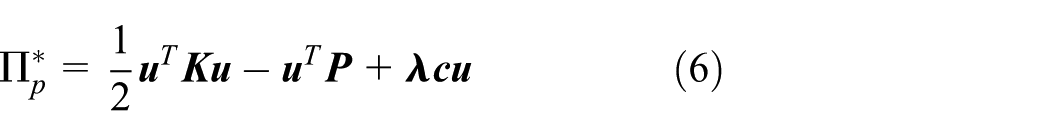
Generally, the interval finite element equation for the static boundary value problems is described as

where
For the interval finite element method based on EBE,
15
it is assumed that the interval parameters between each element are independent, and the interval parameters in the element are interrelated. By separating the elements and using the EBE technique, the structural global stiffness matrix is assembled to eliminate the correlation of adjacent units during the coupling process in the common junction. Supposing the uncertainty of the elastic modulus is

where
The assembled stiffness matrix is singular because the mutual restraints between elements are released by the separation of elements. To remedy the displacement compatibility condition after the separation of the EBE system, additional constraints should be imposed. Suppose the compatibility of displacements is as follows

where
where
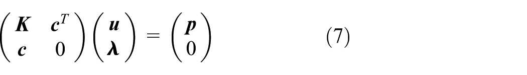
Considering the uncertainty of the parameters, we have

Define
Thus, equation (8) is transformed into

According to the fixed-point iterative method,16,17 the solution of the equations is


where
The response displacement interval and the Lagrange multiplier interval of the structure can be separated from


where the Boolean matrix
Improved interval finite element method based on EBE
Note that the structural stiffness matrix
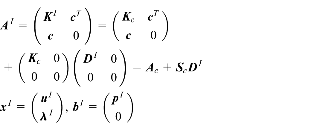
The displacement interval compatibility condition is transformed as
Substituting equation (14) into equation (8), we obtain

where

The iterative process is expressed as follows


Assume


where
If only the uncertainty of the elastic modulus of the material is taken into account and load
The initial conditions for the above iterative computations are

The converge condition is
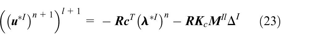
According to numerical experiences, the iteration equations (19)–(22) converge after only two steps; at this time, n equals to 1. According to equations (19) and (20), the Lagrange multiplier solution of the equations is


The initial multiplier vector


In the same manner, the interval part equations (22) and (23) can be changed to


When the interval Lagrange multiplier

The response displacement interval and the Lagrange multiplier interval of the structure can be obtained easily and efficiently using the improved interval finite element method based on EBE. The Lagrange multiplier interval can be converted for the element nodal force interval. In the displacement interval finite element, the nodal force interval of element is described as

where

Substituting equation (34) into equation (33) yields

In system of bars, equation (35) provides a method for effectively calculating the axial force of a member bar.
A new interval stress solution method
In the traditional finite element method, the nodal force of element can be obtained by the element stress

where
For a three-node triangular element, the strain matrix

where
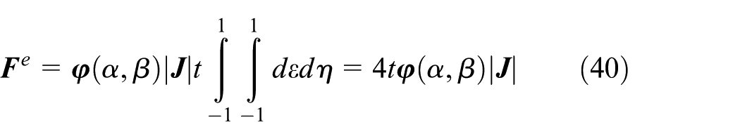
For a quadrilateral element, the element integral form of the natural coordinate system is obtained via equation (36) as

For rectangular or parallelogram elements, the Jacobian matrix

Because the stress inside the element is continuous, that is,
where

Equations (37) and (40) can be uniformly expressed as

where

Because

Considering the uncertainty of the structural parameters, the interval stress of the element is

Substituting equation (35) into equation (45) yields
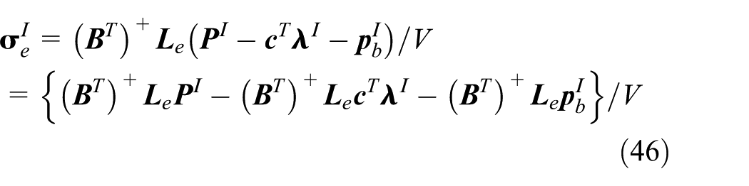
From the properties of the generalized inverse matrix, we obtain

A reasonable element stress interval can be obtained by delaying the interval multiplication operation in the calculation process as long as possible. The method is strict and effective for triangular and rectangular or parallelogram elements, and the stress interval for the general quadrilateral element is an approximation.
Numerical examples
Plane truss example
Here, a plane truss 13 is considered; the truss is composed of m-bar –n-layer members. The left node of the truss is subjected to a horizontal concentrated load, and the upper node is subjected to a vertical concentrated load, as shown in Figure 1, where the load is 10 kN, elastic modulus of bars E = 210 GPa, the cross-sectional area is 0.0025 m2, and L is 1 m. Considering the uncertainty of the cross-sectional area of the element, the uncertainty is 1%. The different m and n values are calculated. The computer is running on the Windows 7 operating system using a processor operating at 1.6 GHz, and the memory is 1.5 GB.
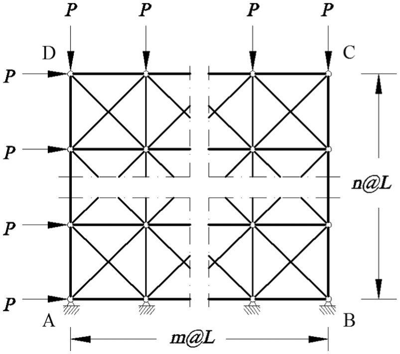
m-bar –n-layer truss structure.
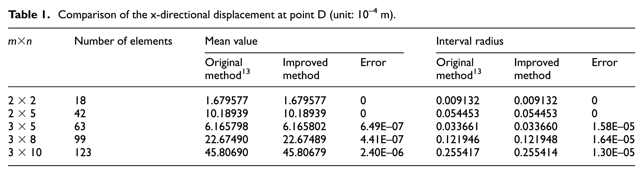
Table 1 presents the comparison between the results obtained by the original method 13 and the improved method of the horizontal x-displacements at point D, and Table 2 presents the corresponding comparison of the axial forces at element 1. Tables 1 and 2 show that the results obtained by the improved method are basically the same as the results of the original method, 13 and the error is very small, demonstrating that the improved method is reasonable and feasible.
Comparison of the x-directional displacement at point D (unit: 10−4 m).
Comparison of the axial force of element 1 (unit: kN).

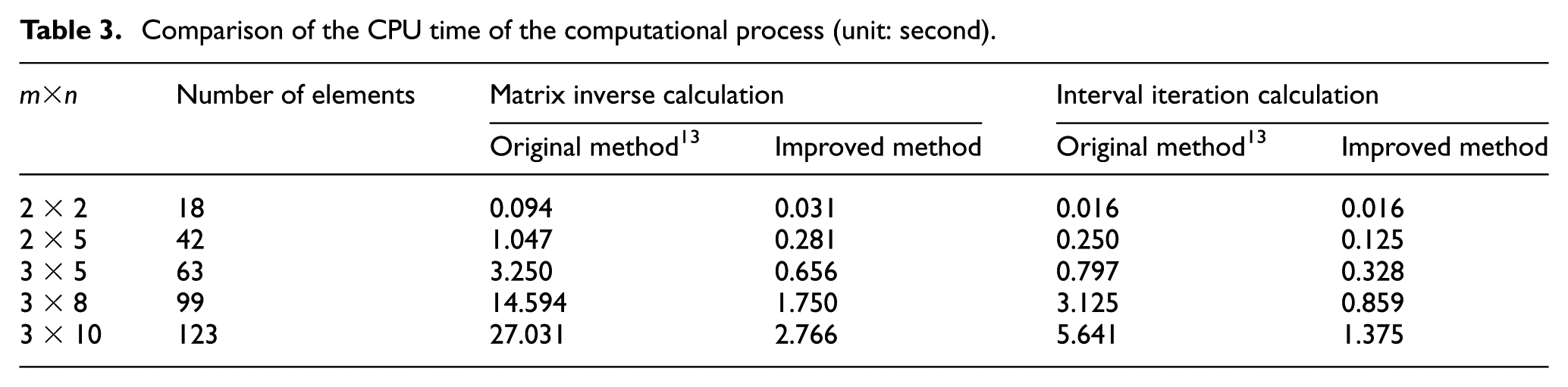
Table 3 shows the comparison between the original method 13 and the improved method of the time consumption of the matrix inversion and interval iteration process, and Figure 2 shows the relationship curve of the central processing unit (CPU) time and the number of interval variables. It may be seen from Table 1 and Figure 2 that the computational time increases with the increase in the number of interval variables and the matrix inverse process takes up more computation time. The improved method reduces the storage scale of the matrix, thereby obviously improving the calculation efficiency.
Comparison of the CPU time of the computational process (unit: second).
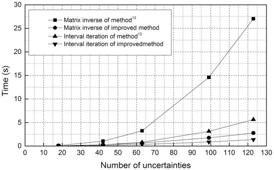
CPU time versus problem scale for the original method 13 and the improved method.
Plane quadrilateral element example
Consider the plate with a quarter-circle cutout 13 shown in Figure 3. The plate has dimensions of 0.1 m × 0.05 m with a thickness of 0.005 m, and the radius of the circular cutout is 0.02 m. Let Poisson’s ratio be v = 0.3 and the elastic modulus be E = 200 GPa. A uniformly distributed load of 100 kN/m is applied to the right edge, as shown in Figure 3. The plate is analysed as a plane-stress problem.

Quadrilateral mesh model of plate with quarter-circle cutout.
Considering that the uncertainties of the elastic modulus of the material are 1%, 5% and 10%, Table 4 gives the comparison of the results obtained by the original method 13 and the improved method of the x-directional displacement at point A, Table 5 gives the comparison results of the y-directional displacement at point E, Table 6 gives the comparison results of the x-directional nodal force at node 14, and Table 7 gives the comparison results of the y-directional nodal force at node 14. It may be seen from Tables 4–7 that the results obtained by the improved method are basically the same as the results of the original method, 13 and the error is very small, demonstrating that the improved method is reasonable and feasible for the planar solid elements.
Comparison of the x-directional displacement at point A (unit: 10−5 m).

Comparison of the y-directional displacement at point E (unit: 10−5 m).

Comparison of the x-directional nodal force at node 14 (unit: kN).

Comparison of the y-directional nodal force at node 14 (unit: kN).

Considering that the uncertainties of the elastic modulus are 1%, 5%, 10% and 15%, Table 8 gives the comparison results obtained by the endpoint combination method, the original method 13 and the improved method of the centroid stress at the element 6. Figures 3 and 4 show the change curves of the stress interval width in the x-direction and the y-direction at element 6 as a function of the uncertainty of the elastic modulus for the three methods. Table 8 reveals the following: (1) the element interval stresses obtained by the original method 13 and the proposed method are less than those of the endpoint combination method, in agreement with the inherent characteristics of the two methods; (2) the results of the proposed method are superior to those of the original stress interval method; 13 and (3) with the increase of interval uncertainty, the result of the original method 13 is increasingly deviated from the reasonable range; on the contrary, the proposed method can give more reasonable element stress interval, as confirmed in Figures 4 and 5. Figures 4 and 5 also reveal that the improvement effect of the x-direction stress interval is more obvious than the y-direction stress interval because the x-direction is the direction of the load, and the stress value is greater than that in the y-direction; as a result, the magnitude of the medium value in the interval iterative method has a significant effect on the interval width.
Comparison of the element centroid stress at element 6 (unit: MPa).


Stress interval width of the x-direction versus the uncertainty of the elastic modulus.

Stress interval width of the y-direction versus the uncertainty of the elastic modulus.
Conclusion
In this article, an improved interval finite element method based on the EBE technique was proposed. In the proposed method, the original governing equations of finite element method (FEM) are divided into two parts, namely, the displacement equations and the Lagrange multiplier equations, and the iterative process is used to solve the corresponding equations. With an increasing number of the unknown Lagrange multiplier equations, the process of solution of structural response displacement is not affected, and it can obtain the structural response interval displacement and the interval force with the same precision at the same time. The numerical examples showed that the improved method has the same accuracy as the original method, but it greatly improves the efficiency of the solution of the large-scale bar system.
A new method of solving the element stress was proposed by applying the improved method to the plane problem. In the proposed method, the element centroid stress interval can be solved by the element node force interval, and high accuracy of the element interval stress can be guaranteed. A numerical example showed that the improved method can maintain the interval accuracy, in agreement with the original method, 13 and even when the uncertainty of the structure is large, reasonable interval results can be obtained using the proposed method.
Footnotes
Acknowledgements
The authors would like to express appreciation to the editor and anonymous reviewers for their valuable comments and suggestions.
Handling Editor: Shun-Peng Zhu
Declaration of conflicting interests
The author(s) declared no potential conflicts of interest with respect to the research, authorship and/or publication of this article.
Funding
The author(s) disclosed receipt of the following financial support for the research, authorship and/or publication of this article: The majority of the work presented in this paper was funded by the National Natural Science Foundation of China (grant nos 51679081 and 51709093) and the Fundamental Research Funds for the Central Universities (2016B07614).