
Abstract
Due to stringent regulations, there has been considerable effort to reduce NOx emissions. In this study, we numerically investigate the details of NOx reduction in a mid-/large-sized combustion system employing a new novel flue-gas internal recirculation burner is thoroughly studied with emphasis on the effects of buoyancy and thermal radiation. The NOx emission in the flue-gas internal recirculation combustion system is observed to be half the value in the non-flue-gas internal recirculation system due to lowered temperature. The present combustion system is large enough for the natural convection to be established and as a result the buoyancy effects become remarkable even though the fuel and air are introduced in the transverse direction. Interestingly, the buoyancy augments the NOx formation in the non-flue-gas internal recirculation system, whereas it reduces the NOx emission in the flue-gas internal recirculation system. Contrary to the thermal radiation, the buoyancy effects in large-sized combustion systems have not been systematically studied yet. Also, the numerical prediction of NOx emission with computational fluid dynamics is accurate only when the buoyancy and thermal radiation are considered together. The present finding about NOx emission, buoyancy, and thermal radiation is expected to be very useful in innovating the ultra-low NOx combustion systems.
Keywords
Introduction
Nitrogen oxides (NOx) are among the most hazardous environmental pollutants, causing significant environmental threats such as acid rain, photochemical smog, tropospheric ozone depletion, and global warming.1,2 Recently, regulations pertaining to NOx emissions from industrial combustion facilities are becoming more stringent and the allowable NOx levels are continuously decreasing to single-digit ppm values. 3 Such low levels can be achieved only by cooperating the existing diverse NOx reduction techniques (e.g. fuel/air staging, partially premixed flame, divided flame, flow recirculation, enhanced mixing with swirling), in which three major conditions for NOx reduction are simultaneously fulfilled: (1) low flame temperature, (2) fuel-rich condition at the maximum flame temperature zone, and (3) short residence times in oxidizing regions.3–5
For clean fuel (e.g. natural gas), the NOx from combustion can be classified as thermal and prompt NOx according to the type of reaction involved during the NOx formation process. Thermal NOx is formed from the reaction of atmospheric nitrogen and oxygen in a high-temperature environment (known as the Zeldovich mechanism),6–8 while prompt NOx is generated from a complex chain reaction of atmospheric nitrogen with radical hydrocarbons at a low temperature during which NOx precursors are rapidly oxidized to NO.9,10
Flue-gas recirculation, known to be a very effective manner of reducing the peak flame temperature and thereby suppressing thermal NOx, 11 is classified as external and internal type depending on where the recirculation happens. In external flue-gas recirculation (EGR), the exhaust gas is added to the combustion air externally via an additional piping system. However, in flue-gas internal recirculation (FIR), the flue gas is recirculated inside the chamber. The FIR is usually implemented aerodynamically by a specially designed burner (FIR burner) that mixes the flue gas with air and/or fuel prior to combustion. Since the FIR combustion system does not require any additional equipment or piping, the system efficiency is not changed. Also, the mixing with the flue gas preheats the combustible mixture and recycles the waste heat.12–14
In this study, we consider a novel low-NOx burner based on the FIR (see Figure 1). Since the flue gas is mixed with combustion air before being injected into the chamber (primary outlet 2; PO2) in this design, the present approach can be more precisely referred to as the air-FIR method. If the flue gas is merged with fuel, the method is named fuel-FIR. In this article, unless specified otherwise, FIR stands for air-FIR. As presented in Figure 1, the primary fuel introduced into the central passage of the burner (fuel 1) is mixed with air to form a partially premixed gas before entering the chamber through a swirler (primary outlet 1; PO1). The secondary fuel is provided directly from the burner to the chamber via tilted holes on the spud (secondary outlet; SO). The flue gas returns to the burner (inlet for FIR; IFIR) and is then mixed with air, after which it is reinjected into the chamber at a high speed, giving rise to FIR inside the chamber.
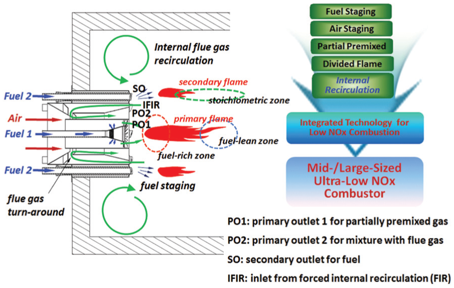
Schematic (left) and concept (right) of the present low-NOx combustion system.
With rapid development of computational resources, the use of computational fluid dynamics (CFD) for the design of a novel low-NOx combustion system is getting more and more popular these days because it can reduce the experimental cost and accelerate the design cycle. For example, Sărlej et al. 15 tested various arrangements and slewing angles of secondary fuel nozzles in a fuel staging burner to determine the optimal design to achieve the minimum NOx outlet concentration. Chen and Liu 16 simulated a three-dimensional (3D) model of a 10-MW air staging gas burner. However, they considered the burner and the chamber separately, which could cause some errors in NOx predictions. Liu et al. 1 used the CFD approach to investigate the effect of the angles of primary gas and staged gas nozzles on the NOx emission of a fuel staging burner. Kim et al. 17 evaluated a fuel-lean reburning method for low NOx emissions. Their study showed that the recirculation flow inside the chamber plays an important role in the reburning process. Huang et al. 18 performed a CFD analysis of an axially staged combustor and found that the axial properties of the inlet flow significantly affect the combustion characteristics and NOx formation. They also found that a high axial velocity is important for the rapid mixing of the gas, lowering the flame temperature and reducing the NOx emissions.
In this study, the comprehensive full 3D CFD analyses are conducted on a low-NOx combustion system with a dual focus on buoyancy and thermal radiation. The present combustion system employs a new type of burner with the FIR configuration. To ensure a systematic approach, we consider four cases depending on the presence of buoyancy and thermal radiation for each of the FIR and non-FIR systems assessed (case A—no buoyancy and no thermal radiation; case B—buoyancy alone; case C—thermal radiation alone; case D—buoyancy and thermal radiation together). The present CFD approach employs the Navier–Stokes, energy, and species conservation equations. The standard k−ε model is utilized for turbulence modeling, while the turbulence–combustion interaction is modeled with the eddy dissipation model. The discrete ordinates (DO) model is used to discretize the radiative transfer equation, and the radiative properties of the combustion product are modeled by the weighted-sum-of-gray-gases model (WSGGM). This study enables a comprehensive understanding of a low-NOx combustion system by examining the temperature, velocity, species, and NOx emission distributions. As a result, deep insight into the effects of the FIR, buoyancy, and thermal radiation on low NOx emissions can be acquired through this study.
Computational system
The computational system considered in this study consists of a burner and a simple combustion chamber.
FIR versus non-FIR burner
Distinguished from conventional low-NOx burners, the present burner is specially designed to generate FIR aerodynamically inside the combustion chamber to achieve ultra-low NOx level (denoted as an FIR burner). The FIR burner draws back the flue gas from the chamber and ejects a mixture of flue gas and air. In this study, the combustion system with the FIR burner (FIR system) is thoroughly examined through a comparison with a non-FIR system without the FIR function. Figure 2(d) and (f) shows the cross-sectional views of the FIR and non-FIR burners, respectively. As described briefly in the introduction, a partially premixed gas of fuel and air is introduced into the chamber through a swirler in the center (PO1) and the secondary fuel is injected via eight spud nozzles (SO). The swirler and the spud nozzle were inclined to produce a rotating flow at the outlets. The swirler and spud are inclined in opposite directions to enhance mixing of the fuel and the gas. PO2 introduces the air–flue gas mixture into the FIR burner. The FIR burner also has an opening to draw back the flue gas to the burner inside from the chamber (IFIR). The key difference in the geometry between the FIR and non-FIR burners is the recirculation sleeve inside the burner. It forms a guided passage with the turn-around of the flue gas (see Figure 2(d) and (e)). In the non-FIR burner, there is no such metallic barrier, and pure air is introduced into the chamber via PO2 (see Figure 2(f) and (g)).

Burner overviews and flow motion inside non-FIR and FIR burners: (a) burner (outer view), (b) burner (front view), (c) swirling flow, (d) FIR burner system, (e) FIR flow structure, (f) non-FIR burner system, and (g) non-FIR flow structure.
Combustion system
A schematic of the combined system with the burner and the model chamber for the numerical computations is shown in Figure 3(a). The dimensions of the model chamber were set as L = 5.621 m (length, in the z-direction), W = 1.876 m (width, in the x-direction), and H = 3.267 m (height, in the y-direction), which were taken from those of a typical mid-sized water-tube boiler at the Korea Institute of Industrial Technology (KITECH). Because the convective heat flux is expressed as
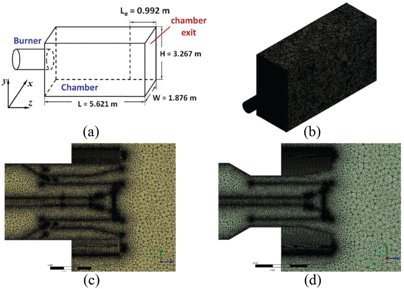
(a) Schematic of the combined burner and chamber system, (b) computational meshes, (c) mesh for the FIR burner, and (d) mesh for the non-FIR burner.
NOx emission model
Since a clean natural gas is assumed, we consider the thermal and prompt NOx only. The formation of thermal NOx was modeled with the extended Zeldovich mechanism,6–8 as shown below


Here, the reaction coefficients are given as follows


and

In the above expressions, the reaction coefficients of k+1, k+2, and k+3 are for the forward reaction and k–1, k–2, and k–3 are for the backward reaction rates. The net rate of NOx formation from equations (1)–(3) is computed as

For the calculation of the formation rates of NO and N, the concentrations of O, H, and OH are required. In this study, partial equilibrium was assumed for O radicals and [O] was computed using the following equation 19

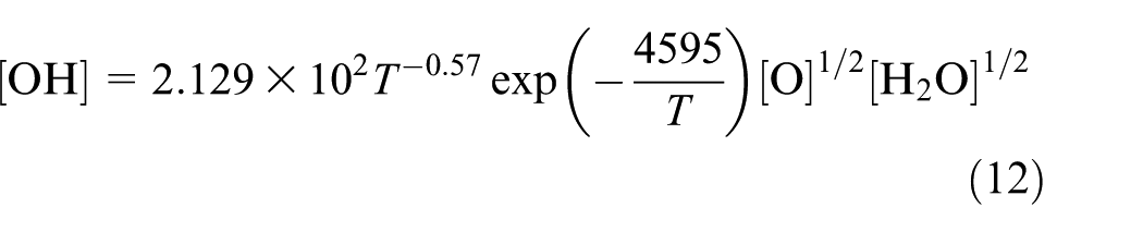
The partial equilibrium assumption was also applied to compute the concentration of OH radicals
Even at a low temperature and with a short residence time, a significant amount of NOx can be produced under a fuel-rich condition, which is indicated as prompt NOx. The chemical reactions for the formation of prompt NOx are written as


and the overall prompt NOx formation rate is given by

In the above equation, f is a correction factor given by

where
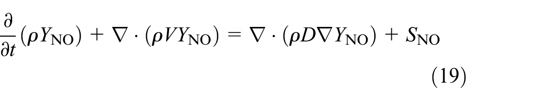
where the source term due to thermal and prompt NOx formation is given by

Numerical analysis
All CFD computations in this study were carried out using the commercial software ANSYS Fluent 16.0. 22 The Reynolds-averaged Navier–Stokes equation was solved along with the energy equation and species conservation equations with reactions. Moreover, the standard k−ε model was employed to include turbulence features in the system. The sets of coupled equations were solved with a pressure-based coupled algorithm, and the PRESTO! scheme was used for pressure interpolations. The eddy dissipation model was used to consider the interaction between the turbulence and chemical reactions. The thermal radiation was included via the DO model for the radiative transfer equation, 23 and the non-gray radiative properties were modeled with WSGGM. 24 When the buoyancy was included, gravity of 9.81 m/s was added to the Navier–Stokes equation along the y-direction.
Results and discussion
Cases considered
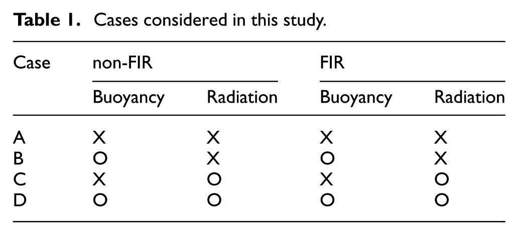
As listed in Table 1, in this study we considered four cases depending on the presence of buoyancy and thermal radiation for each of the FIR and non-FIR systems tested. In case A, neither buoyancy nor thermal radiation is included in the simulation, whereas case D considers both. In addition, case B considers buoyancy only, while case C includes thermal radiation only.
Cases considered in this study.
FIR versus non-FIR burner
For a comprehensive understanding of the effects of FIR on the flow inside the burner, the axial velocity distributions are compared in Figure 4 on the plane cut along A−A′. In the FIR burner, the flue gas in the chamber is drawn back to the burner through IFIR with an axial velocity of approximately 8 m/s, and then it experiences a 180-degree sharp turn around the vented recirculation sleeve (marked in the figure) with mixing with air. The vented recirculation sleeve makes the passage to PO2 narrower, giving rise to a remarkable acceleration of the air–flue gas mixture to PO2. Such a reduction in the cross-sectional area allows more air flow to be delivered to PO1; therefore, the gas velocity at PO1 also becomes higher in the FIR burner in comparison with the value in the non-FIR case. Two high-speed gas flows from PO1 and PO2 are merged soon after the ejection from the outlets, inducing internal recirculation inside the chamber. The axial velocity distribution is not greatly affected by the presence of buoyancy or thermal radiation, because inside the burner the space is not sufficient for natural convection to be established and the inner gas does not have radiatively active CO2 or H2O.

Axial velocity distribution in the combined region of the inside burner and the vicinity of burner outlet. The distributions are drawn for the plane cut along A−A′ line.
In Figure 5, the non-FIR and FIR axial velocity profiles along A−A′ are compared in close proximity to the burner outlet (z = 0.05 m). The r value on the y-axis represents the position along A−A′ with the origin at the center of the line. For the FIR burner, even at z = 0.05 m, the partially premixed gas from PO1 is already well mixed with the air–flue gas mixture from PO2, and it produces a large velocity bump with two small peaks. However, the jet from SO is not yet diminished at the point of z = 0.05 m. The profiles are not affected by buoyancy or thermal radiation, which indicates that the position with z = 0.05 m is too early to observe the effects of buoyancy and thermal radiation clearly.

Axial velocity near the burner outlet (z = 0.05 m).
Differing from those of the FIR burner, the velocity profiles of the non-FIR burner have four distinct peaks at r = ±0.24 and r = ±0.1 m because the flows from PO1 and PO2 are not mixed yet. The sizes of these peaks do not change unless the buoyancy and thermal radiation are considered together (see case D). The inner peak (PO1) grows upon merging of the gas from PO2. For both the FIR and non-FIR burners, the axial velocity has a negative value at the centerline of the chamber (r = 0) due to the strong swirling flow from the burner. To express how much flue gas comes back to the burner out of the gas provided to the combustion chamber, we define the FIR efficiency,

In the equation above,
FIR efficiency

FIR: flue-gas internal recirculation.
Temperature field
Figures 6 and 7 show the temperature fields on the middle xz-plane (y = 0; top view) and on the middle yz-plane (x = 0; side view), respectively. Hereafter, unless specified otherwise, top view indicates the distributions on the middle xz-plane, while side view represents the distribution on the middle yz-plane. Due to the strong swirling flow from the burner, the temperature field is quite complicated; a simple symmetric distribution does not appear.
Temperature distribution on the middle xz-plane with y = 0 (top view).

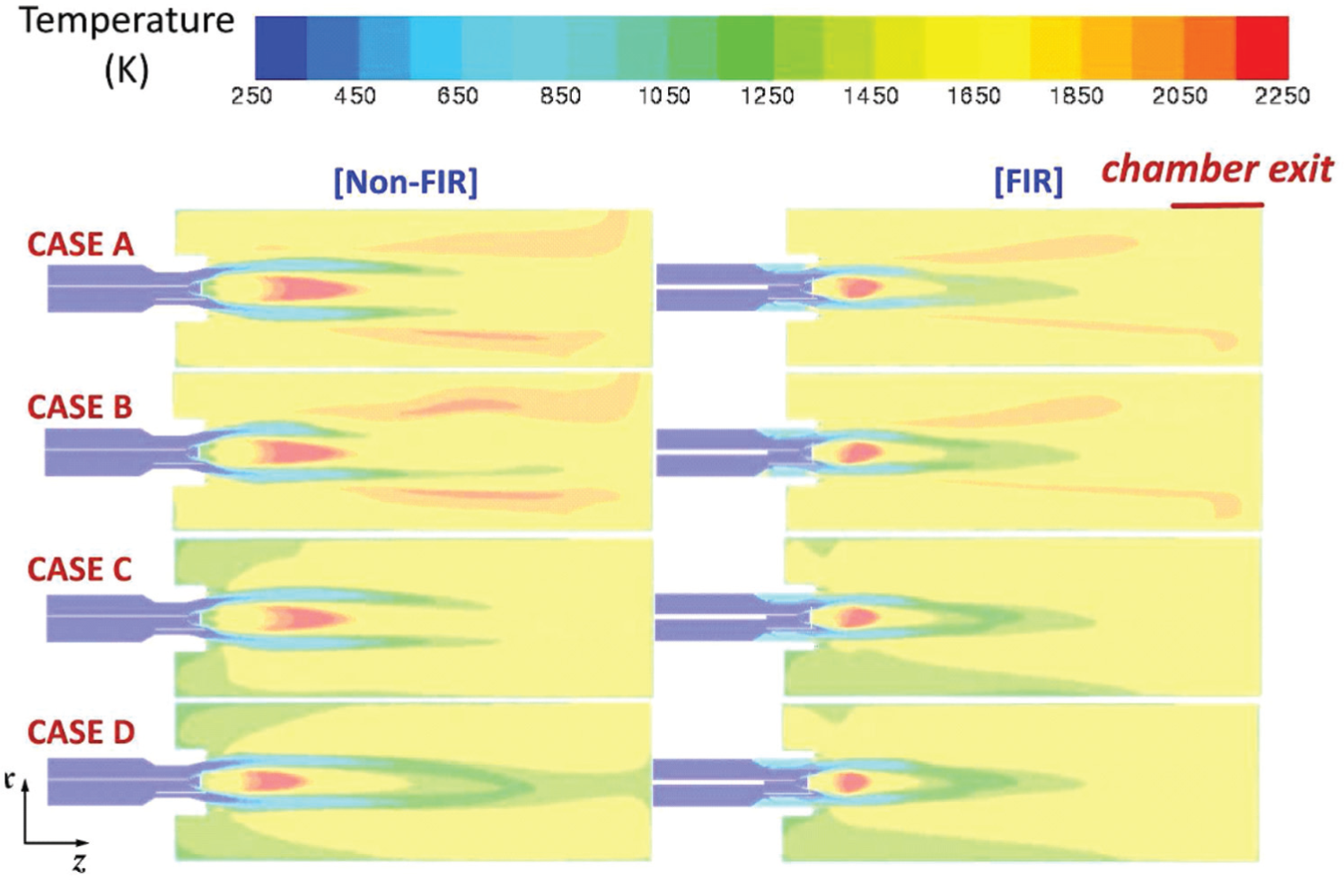
Temperature distribution on the middle yz-plane with x = 0 (side view).
Generally, the entire temperature field in the present combustion system consists of a central area in which a core flame (red) exists and an outer wide high-temperature zone initiated by the combustion of secondary fuel (staged combustion). There exists a narrow low-temperature zone (green) between the central core flame zone and the outer high-temperature zone, and it distinguishes two regions. The core flame can be further divided into the fuel-rich primary combustion zone near the burner outlet and the fuel-lean zone with a suppressed temperature downstream of the primary zone. These stagings help reduce the NOx. 1
From a comparison of the FIR and non-FIR results, the following should be noted: (1) Since the combustion happens faster with FIR, the primary reaction zone is localized near the burner outlet and then the size of primary flame becomes smaller. (2) Compared with the non-FIR case, the temperature at PO2 became higher by about 100 K with the FIR due to the mixing with the flue gas. (3) Because the total amount of energy inside the system defined as
Maximum temperature in the chamber (K).

FIR: flue-gas internal recirculation.
The small core flame in the FIR system is surrounded by a low-temperature pocket (green area). However, for the non-FIR case, such confinement occurs only in cases C and D. In cases A and B, the low-temperature region did not enclose the flame fully. These phenomena arise because for the FIR cases the strong circumferential swirling flow around the core flame is sustained at the far downstream locations, which enhances mixing in cooperation with the recirculation of the flue gas. However, for the non-FIR systems, that circumferential motion decays early and the fluid around the flame is not highly miscible with the chamber gas.
As shown in Figure 7 regarding the temperature field on the middle yz-plane (x = 0), with the presence of buoyancy (case B), the outer high-temperature zone becomes wide and uniform because the natural convection transports the hot gas in the lower side to the upper side. In Figure 6, two hot areas at x < 0 and x > 0 in cases A and B clearly reveal those passages for the hot gas from the lower to the upper part of the chamber, and considerable temperature gradients are formed around the passages. The passages are slightly enlarged with buoyancy because the buoyancy enhances the flow against gravity. This trend appears more prominent for the non-FIR system because the inlet velocity is lower and the flow field is easily disturbed (see Figure 9). For the FIR case, the differences are negligible. In contrast to the outer flame, the core flame shrinks with natural convection, as buoyancy enhances the mixing and the combustion is completed more rapidly. With thermal radiation (case C), the temperature was reduced significantly due to additional heat loss by radiation through chamber exit and to the wall. The thermal radiation also homogenizes the temperature field with expanding the low-temperature region over the entire chamber. Such effects by buoyancy and thermal radiation appear more remarkable for the non-FIR system due to its higher temperature flame (see Table 3).
In Figure 8, another comprehensive investigation of the temperature field is performed by comparing the temperature contours on the xy-plane at various z-positions (z = 0.5, 1.5, 2.5, and 3.5 m). On each plane, the temperature profiles along the y-axis are also compared at x = 0. This figure shows how the injected gases are mixed with the chamber gas and how the secondary fuel from SO establishes the outer high-temperature zone. The circumferential high-temperature ring expands outward with forming a uniform temperature field in the outer region. In the FIR system, the secondary fuel is ignited quickly near SO, while for the non-FIR system the flame is formed further downstream; TFIR > Tnon-FIR at z = 0.5 m, whereas TFIR < Tnon-FIR at z = 1.5 m except in case D. In contrast to the fuel from SO, the temperature of which is rapidly elevated near the burner from its initial value of T = 300 K, the partially premixed gas from the swirler (PO1) already has a high temperature of T = 500∼600 K and is further heated as it flows downstream. However, the gas from PO1 is heated more rapidly in the FIR system than in the non-FIR system because the strong FIR-induced circumferential flow enhances the mixing between the swirling and the secondary flue injection. The weak circumferential flow in the non-FIR system makes the shape of the discrete swirling injections visible even downstream with z = 1.5 m. Details about the correlation between the temperature and the flow fields are discussed below.

Comparison of temperature distributions on the xy-plane with various z-positions.
Flow field
The flow velocity vector in this study was decomposed into

Axial velocity distribution (side view).
The flow structure inside the chamber can be better understood by examining the streamlines, as displayed in Figure 10. For both the FIR and non-FIR systems, two primary recirculating vortices are observed on the upper (y > 0) and lower (y < 0) sides of the chamber. However, for the FIR systems, a secondary vortex additionally appears in the upper left corner, except in case D, because the axial velocity from the burner is strong such that the flow near the left wall (burner side) is isolated from the major flows in the central zone of the chamber. In addition, due to the high-speed jet from PO1 and PO2, the inclusion of buoyancy and thermal radiation does not produce a considerable change in the streamlines. However, in case D (buoyancy and thermal radiation together) with the FIR burner, the low and uniform temperature field weakens this secondary vortex, giving rise to a single large recirculation. For the non-FIR systems, regardless of the presence of buoyancy and/or thermal radiation, the secondary vortex did not appear because the axial velocity is not large enough to generate an isolated region.
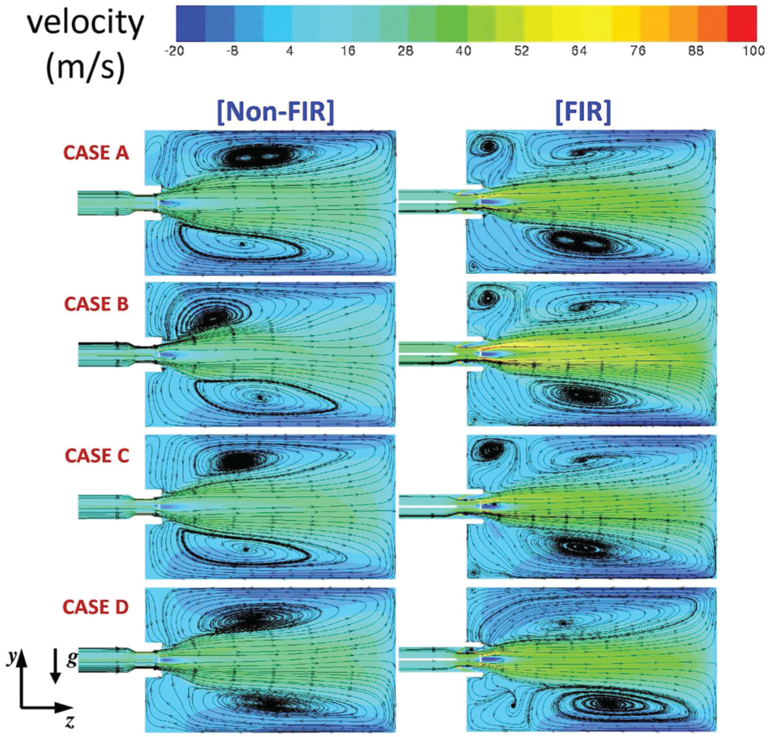
Streamlines (side view).
Figure 11 shows the circumferential flow distribution on various xy-planes with different z-positions. In the figure, the positive circumferential rotation is defined as the swirling direction formed by the burner. The plots at z = 0.5 m show that the flows from PO1/PO2 and SO rotate in opposite directions, which augments the mixing of the fuel and the air. The swirling generated by the burner gradually vanishes as the flow moves downward. The asymmetry in

Comparison of the circumferential velocity distributions at various z-positions.
NOx distribution
Figure 12 shows the NOx distributions and the emission values at the chamber exit for various cases. In the present system, most of the NOx is produced via the thermal mechanism (thermal NOx), while the contribution by prompt NOx is negligible. This figure shows that the NOx emissions are significantly suppressed by the FIR burner, which confirms the rule of thumb that the lower temperature condition forms less NOx. Also, Figure 12 implies that the accurate CFD predictions of NOx emission levels for mid-/large-sized combustion systems are possible only when buoyancy and thermal radiation are considered together. In the experiment, the NOx emission was measured as 18.9 ppm for the combustion system with FIR burner and 35 ppm for the system with non-FIR burner, which indicates that the NOx emission was decreased by about a half with introducing the FIR burner (Kwon and Kim, 2017, private communication). Such dramatic reduction was observed only for the CFD simulation with buoyancy and thermal radiation (case D) as summarized in the table of Figure 12. For case D, the NOx value was reduced from 334 to 177 ppm by replacing the non-FIR burner with the FIR one, which corresponds to the reduction of 47%. Although there exists a difference between CFD and experimental values of NOx production, we can still state that the CFD simulations accurately predict the effects of non-FIR approach on the NOx production, because the reduction ratios are almost the same. Currently, a study to improve quantitative accuracy is being performed. For the other cases, the influence of the FIR is not very remarkable (e.g. in case C, 204 ppm for the FIR and 239 ppm for the non-FIR system).

NOx distribution (top view) and the NOx value at the chamber exit.
As noted in the section “Introduction,” diverse combustion control techniques have been developed to minimize NOx emission by achieving the following conditions:3–5 (1) a low flame temperature, (2) a fuel-rich condition in the region with the maximum flame temperature, and (3) a small residence time in the region where the oxidizing conditions exist. In order to understand the contribution of each factor, in Figure 13 we compare the distributions of the NOx, temperature, and the oxygen mole fraction along the centerline of the chamber (x = 0 and y = 0) in which maximum NOx appears. The NOx emission from the outer flame formed along the stoichiometric line at which the stoichiometric ratio is unity is not considerable because the temperature is low and the residence time is small (high velocity). In the figure, regardless of the FIR and non-FIR cases, the position of the maximum NOx emission,

Comparison of the distributions of NOx along with temperature, O2 mole fraction, and axial velocity for various cases along the centerline.
Interestingly, when including buoyancy, the NOx emission increases for the non-FIR system, whereas it decreases for the FIR system (see the table in Figure 12). For the non-FIR system, although the buoyancy is included, the NOx production is dominated by the temperature because the magnitude of the flow field is not large. However, for the FIR system, the buoyancy effect on the NOx emission is somewhat complicated. From case A to case B, with natural convection the axial flow penetrates farther and the residence time downstream becomes small, suppressing NOx production. In the figure, the observed axial velocity is larger in case B than in case A in the region of 2.0 m < z < 3.5 m. Also, when the thermal radiation is included (cases C and D), the natural convection makes the high-temperature zone smaller (see the region of 0 < z < 1.0 m); thus, NOx production is reduced. To summarize, for the non-FIR system in which the flow is not strong, the NOx production is mostly influenced by temperature—the mixing enhancement due to natural convection induces higher temperature field and the NOx production is augmented. However, for the FIR system, the key factor is flow field—with including natural convection, the axial flow becomes faster as the vertical flow outside is intensified. And the higher axial speed makes the flow residence time smaller and the NOx reduction is reduced.
Conclusion
In this study, the NOx emission in a mid-/large-sized combustion system with a new novel FIR burner was thoroughly investigated through extensive CFD simulations with a focus on the effects of buoyancy and thermal radiation. Thermal radiation was considered by employing the radiative transport equation and the WSGG non-gray gas model. In the present FIR low-NOx burner, the flue gas was drawn back to the burner and then ejected into the chamber with the high speed accelerated by a vented recirculation sleeve inside the burner. The notable findings in the current work are summarized as follows:
The NOx emission was significantly reduced with the present FIR burner, as the size of the local high-temperature zone became smaller and the system temperature was reduced overall.
With the present FIR burner, the recirculation inside the chamber was significantly intensified due to the higher axial velocity from the PO2 burner. However, interestingly the amount of flue gas returning to the burner was less than 5% of that of the total gas introduced to the chamber. Even with such a small number, the effects were dramatic: the gas temperature from PO2 increased significantly, leading to an early ignition and a short flame height as well as a high injection speed.
The maximum O2 occurs in the downstream of the maximum temperature position and the maximum NOx emission is placed between these two points, because the NOx formation rate is determined by the combined contribution of the temperature and oxygen concentration.
At the maximum NOx position, the temperature is high but the oxygen concentration and flow residence time are low. In the non-FIR system, at the maximum NOx position the temperature is not as high as the value in the FIR system, but the amount of NOx emitted is large because the oxygen concentration is high and the flow residence time is long.
The CFD prediction of NOx emission is accurate only when the buoyancy and thermal radiation are considered together, because the experimental observation that NOx emission is reduced to half by employing FIR burner was predicted only for the simulation with buoyancy and thermal radiation together.
As observed in this study, if the chamber dimensions are sufficiently large, the buoyancy effect appears to be considerable even though the fuel and air are injected in the transverse direction. The buoyancy induces a circumferential flow such that the hot gas at the bottom can move to the top by detouring around the core flame. As a result, the high temperature in the outer area becomes wide and uniform and the core flame becomes short by the buoyancy-induced fast mixing.
When the buoyancy was included, in the non-FIR system NOx emission was increased because the temperature field dominates the NOx formation process. However, in the FIR system NOx production became smaller with natural convection due to reduced flow residence time.
The radiative heat transfer increases the heat loss and lowers the chamber temperature. Hence, NOx production is reduced.
The NOx reduction mechanism in the FIR system was altered by the thermal radiation. Without thermal radiation, NOx emission was controlled by the flow field, while with thermal radiation NOx formation was affected mainly by the temperature field.
Footnotes
Handling Editor: Moran Wang
Declaration of conflicting interests
The author(s) declared no potential conflicts of interest with respect to the research, authorship, and/or publication of this article.
Funding
The author(s) disclosed receipt of the following financial support for the research, authorship, and/or publication of this article: This work was supported by the Energy Efficiency & Resources of the Korea Institute of Energy Technology Evaluation and Planning (KETEP)-granted financial resource from the Ministry of Trade, Industry & Energy, Republic of Korea (No. 20152010103050). This work was also supported by the Gyeongsang National University Fund for Professors on Sabbatical Leave, 2016.