
Abstract
For the main shaft of wind turbine of certain type, shaft fracture occurs at the variable section of the shaft during early stage of operation. In order to validate the failure analysis, finite element analysis of the main shaft was performed. The analysis results demonstrate that there is a severe stress concentration that leads to the formation of initial cracks at variable inner diameters of the main shaft. Also, the stress in the variable part mainly resulted in the pressure of the bulging joining sleeve applied on the main shaft via the gearbox planet carrier shaft. According to the above analysis, local structure improvements were carried out through increasing the action area between the bulging joining sleeve and the main shaft. The finite element simulation results show that the stress concentration in the variable section of the improved shaft decreases significantly. The improvement of shaft strength decreases the possibility of crack formation and its growth, thus enhancing the reliability of the main shaft. This analysis process and the results of this study can provide a reference in shaft fracture analysis and also technical support for improvement in the design of wind turbine main shafts.
Introduction
Wind is a clean and reproducible energy, which is the fastest growing energy source. Furthermore, wind energy market has achieved substantial growth over years, especially in the United States and China. In most situations, wind turbines are not easily accessed due to the remote locations of mountain areas or offshore. Once certain components of the unit fail, the loss of power-generating capacity is inevitable. In the meantime, a mass of manpower and material resources are required to replace the components. Although the design working life of wind turbine is over 20 years, the operation and maintenance costs of the units may account for 10%–15% of the revenue of the wind power stations. 1 Especially, unplanned failures of the key components can be very expensive. Because of the complexity of the systems and the components of a wind turbine, it can be challenging to identify the core causes of a failure.
According to the guidelines and standards for wind turbine generating system (WTGS), generally wind turbines are designed with a working life of at least 20 years.2,3 As shown in Figure 1, the fault statistics of the wind turbine shows that the outages caused by the main shaft failure account for less than 0.1% (marked in blue), but its downtime accounts for a very large share, about 24.8% (marked in red). 4
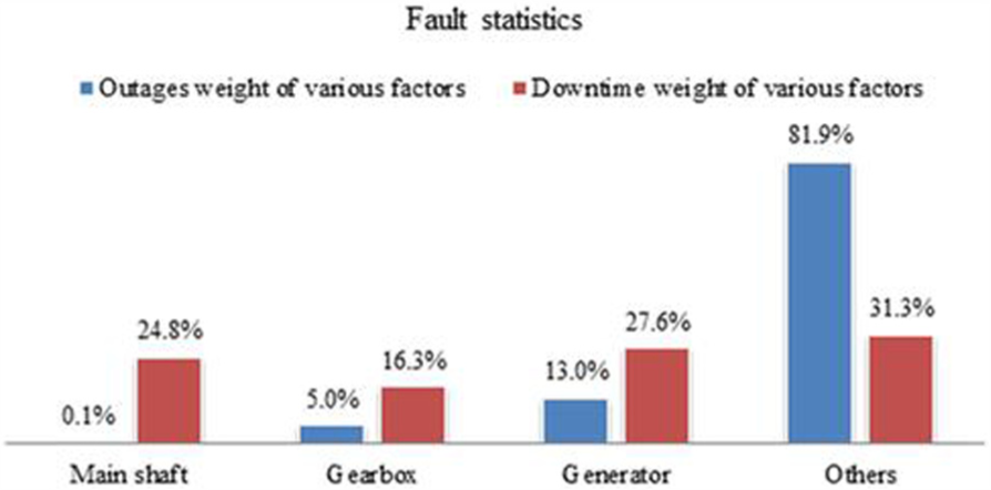
Outages and downtime weights of wind turbine faults (Guohua Energy Investment Co., Ltd.).
Although many scholars have been engaged in failure detection and fault diagnosis of wind turbine,5–8 there are still many issues that are unresolved such as life prediction of key components and efficient prognosis health management. Many papers focusing on fault diagnosis of various key components of turbine blades, support bearings, and transmission gearboxes have been published.9–12 The main shaft is a critical component in the wind power station, which carries variable forces transmitted by the system. It has been reported that certain type of main shafts of wind turbine units have fractured prematurely after 4 years of performance. The failure leads to significant economic losses to the wind farm.
A model of WTGS is the research object that belongs to the double-fed wind turbine shown in Figure 2. The parameters of the power system are 850 kW rated output power and 1500 rev/min rated rotation speed. The weight of the main shaft is 1260 kg and its highest speed is 24.3 rev/min.

Schematic diagram of the wind turbine.
The WTGS that produced the main shaft fracture in this study was designed for European environments with operation temperatures ranging from –20°C to +40°C. In 2007, this batch of WTGS was installed in Northern China where the temperature can be as low as –40°C in cold winter and finally crashed between October 2011 and February 2012, with a working life of just 4 years.
The studied main shaft is made of 34CrNiMo6 steel with heat treatment. 13 The material properties of the main shaft steel can be referred from Siemiątkowski et al. 14 The shaft is supported by two-point self-aligning roller bearings, which endure transmission torsion, transverse moment, and axial force from the hub and gearbox. The fracture position and the connection of the shaft output are illustrated in Figure 3.

The supporting arrangement of the main shaft and fracture position.
Based on the observation and actual measurement, the fracture position located in the variable diameter section of the main shaft, which is shown in Figure 4.

Image of fracture surface.
To analyze the root cause of shaft failure, the mechanical tests of the material of the shaft were first carried out to verify the quality of the material. Second, the static stress analysis and strength calibration based on finite element method (FEM) were performed according to the Fatigue, Aerodynamics, Structures, and Turbulence (FAST) procedure. Finally, in order to solve this problem, local structure improvement of the main shaft is carried out.
Fracture analysis of the main shaft fracture
For the purpose of thoroughly analyzing the dominant cause of main shaft fracture, this study consists of two parts: (1) material verification of the main shaft and (2) static stress analysis and strength calibration of the main shaft based on FEM.
Experimental analysis
To verify the quality of the main shaft material and determine whether or not the material defect caused its fracture, in this study the mechanical property tests of the material of the main shaft were carried out.
Mechanical property test
Tensile strength and impact strength tests were performed to verify the quality of the main shaft material. Based on the ISO Standards, the specimens were processed15–17 to test the properties of the shaft material such as tensile strength and impact strength (see Figure 5).

Dimensions of the specimen for tensile test.
Two groups of six test specimens were used in the tensile and impact tests by the universal testing machine, respectively. The stress–strain curve and the specimens after the mechanical test are shown in Figures 6 and 7.

The stress–strain curve of one tested specimen.

Specimens after mechanical test.
From the test results, the mechanical properties are listed in Table 1.
Mechanical properties (using mean value).

The tensile strength and impact properties of the main shaft at low temperature are insufficient compared with the EN10083-3:2006 Standard. As mentioned previously, the WTGS crashed in winter, so it can be considered that the insufficient mechanical properties of the shaft material have some influence on the fracture of the main shaft.
Rockwell Hardness machine was used to test the hardness of the specimens with the sampling points taken along the longitudinal axis of the shaft. The sampling points for hardness test are shown in Figure 8. The hardness values ranged from 26.7 to 29.9 HRC with a mean value of 28.1 HRC as shown in Figure 9.

Sampling points for hardness test.

Data of hardness test.
The HRC value of the quenched and tempered (QT) 34CrNiMo6 steel has a typical hardness value of 271–331 HB (27.1–35.3 HRC). 18 The results of the hardness test show that the measured values at certain points of the main shaft from the inner diameter to the mean diameter are below the standard value (see Figure 9). As the hardness can reflect the strength of the materials to a great extent, the hardness result indicates that the material strength of the main shaft is insufficient.
Finite element analysis
For a more detailed understanding of the stress distribution of the shaft, the analysis of the stress state of the wind turbine main shaft was carried out by FEM. In this article, the stress values were analyzed under the rated load condition and the impact condition, respectively. For the convenience of analysis, the screw holes and pin holes on the flange were ignored as they have very little effect on the stress state of the main shaft.
As shown in Figure 10, the discrete model of the main shaft was presented by 137,675 elements with 8-node hexahedron reduced integration elements (C3D8R unit). To obtain a more accurate description of the stress state in the key structural positions of the shaft that may result in large stress, including the transition fillet, shaft shoulder, and unloading slot, the shaft grid was moderately refined. To avoid local stress distortion caused by direct application of the boundary conditions on the main shaft, 19 a part of the planet carrier of the gearbox that is in direct contact with the main shaft, on which the radial pressure was applied to simulate the effect of the bulging joining sleeve, was added in the model:
Applying constraints
The front bearing surface: The displacement degrees of freedom of the rigid surfaces in the three-dimensional (3D) directions and the rotational degrees of freedom about the X axial direction were constrained to express the aligning performance of the bearings;
The interface between the planet carrier and the bulging joining sleeve: setting the interface as the contact;
The outer surface of the planet carrier: The displacement degrees of freedom of the planet carrier center in the 3D directions and the rotational degrees of freedom about the X axial direction were constrained.
Imposing loads
Hub center: A reference point was established in the hub center and coupled with the flange surface. The wind loads
The interface between the planet carrier and the bulging joining sleeve: Radial pressure was applied on the outside surface of the planet carrier to simulate the force that the bulging joining sleeve imposed on the planet carrier.

The model of the wind turbine main shaft.
The FEM analysis of the main shaft was conducted with the applied loads on the main shaft under the rated load condition and impact condition, respectively.
Load acquisition
In order to obtain a reasonable stress distribution of the main shaft, the key point is to obtain the realistic loads of the main shaft. The wind loads are obtained by aerodynamics analysis using the FAST procedure in this article. 20 The FAST code can be used to aeroelastically simulate the extreme and fatigue loads. FAST with AeroDyn 21 was validated by Germanischer Lloyd WindEnergie. 22 So it is of practical significance to utilize the FAST procedure to conduct the dynamic simulation analysis in this article.
The analysis progress is shown in Figure 11. The nonlinear equations of motion are simulated with time marching. While the simulation is ongoing, the aerodynamic and structural response of the wind turbine to wind inflow conditions is timely decided. In the process of simulation analysis, many aspects of turbine operation can be controlled actively. FAST calls the full-field background wind files generated by the TurbSim 23 subroutine and uses the AeroDyn subroutine package to generate aerodynamic forces along the blade. The simulation results consist of the time series data of aerodynamic loads and the load and deformation of the wind turbine structural members.

Analysis flow chart of wind loads.
In this article, the wind models, namely, Normal Turbulence Model (NTM) and 3EWM50 (Class III turbulent Extreme Wind Speed Model, 50-year recurrence), were used to simulate the rated wind loads and the extreme loads of the wind turbine. In addition, the radial pressure of the shaft tail is calculated according to the formulae in Section 2.6.2 of Zhang et al. 24 The wind wheel gravity is calculated according to its mass (11.5 t).

where p is the radial pressure, T is the rated torque, d is the fit nominal diameter, f is the friction coefficient, and l is the length. And the values of these parameters are listed in Table 2.
Parameter list.

Based on the previous research and simulation results, it is found that the structure of the load under the current setting has not reached the yield. Therefore, the definition of the linear elastic material constitutive model is adopted, mainly considering the elastic modulus, Poisson’s ratio, density of the input, without considering the plastic part of the material properties, and the material of the stress–strain curve after yield input.
FEM analysis under rated load condition
Applying loads and constraints, the FEM analysis of the main shaft under the rated load is conducted, the results of which are shown in Figures 12–14.

The stress distribution of the main shaft under rated condition (MPa).
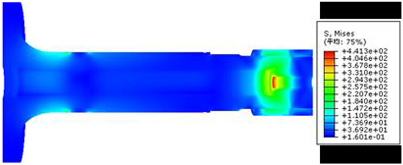
The internal stress distribution of the main shaft under rated condition (MPa).

Magnified view of stress distribution of the shaft for rated condition (MPa).
As shown in Figures 13 and 14, there is serious stress concentration in the variable radius section of the shaft tail and the front edge of the front main bearing surface. The maximum equivalent stress of the main shaft, about 441.3 MPa, appears in the front edge of the minimum inner diameter at the end of the shaft. The equivalent stress in the front edge of the front main bearing surface roughly equals 304 MPa. The equivalent stress in the front edge of the front main bearing surface equals 247.6 MPa.
The results of the FEM analysis are consistent with the characteristics of the variable radius section of the fracture main shaft. The marked area in Figure 15 is one of the fatigue sources, which was caused by stress concentration of the transition fillet in the variable diameter section of the main shaft inner diameter and is characterized by the cowrie pattern lines, with the direction of extension from the internal to the external surface.

The image of the fracture surface.
Based on the guideline for the certification of wind turbine,
2
the yield strength,

In this case

where the parameter S represents the minimum safety margin of the shaft material.
The safety margin of the main shaft is above zero, which indicates that the strength of the main shaft can transmit the normal working load.
FEM analysis under impact load condition
The main shaft endures huge impact load in case of variable wind loads and WTGS emergency start or stop. The effect of the impact load is mainly reflected in the twisting action on the main shaft. As reported in Xie et al.,
25
during emergency braking, the maximum torque is capable of reaching 2–3 times the rated torque. In this article, during the process of FEM analysis of the main shaft under the impact load condition, the torque

The stress distribution of the main shaft under impact condition (MPa).
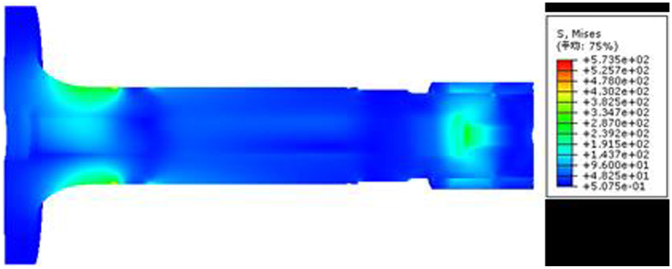
The internal stress distribution of the main shaft under impact condition (MPa).
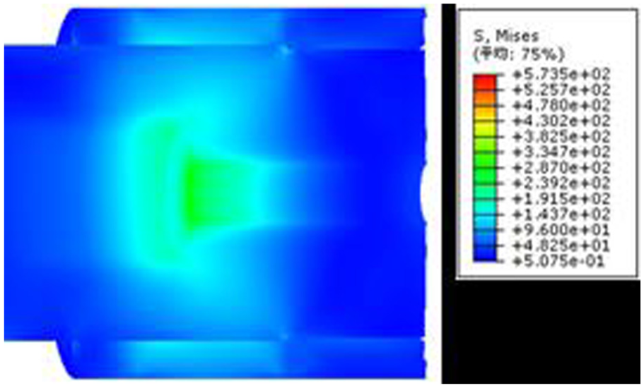
Magnified view of the internal stress distribution under impact condition (MPa).
The maximum equivalent stress of the main shaft, about 573.5 MPa, appears in the front edge of the front main bearing surface. The equivalent stress of the transition fillet in the variable radius section in the main shaft tail equals 305.5 MPa. As shown in Figures 13 and 14, there is serious stress concentration in those two places.
Under the impact load condition, we have

The safety margin of the main shaft is also above zero.
The main shaft material contains defects, which makes it easy to produce initial cracks. The initial cracks extend continuously under large alternating loads. When the actual bearing area cannot sustain the limit impact load, the main shaft fractured.
From the above results, it can be seen that the majority of the stresses are at the elliptical arc transition surface and the tail which is held by the bulging joining sleeve is much larger than the other positions of the main shaft (see Figure 16). From the detailed view shown in Figure 16, the variable radius section and the interaction zone between the elliptical arc transition surface and the front bearing surface experienced severe stress concentrations.
In contrast, the stress distribution of the main shaft under the rated load conditions and impact conditions, the stress in the elliptical arc transition surface increased significantly, especially in the interaction zone between the elliptical arc transition surface and the front bearing surface, from about 247 to 573.5 MPa. While the stress in the shaft tail which is held by the bulging joining sleeve experienced little changes, it increased from about 304 to 305.5 MPa, which draws a conclusion that stress in this position is mainly affected by the radial pressure that the bulging joining sleeve imposed to the shaft via the planet carrier of the gearbox.
Structure improvement
As reported in the previous analysis, there is severe stress concentration in the interaction zone between the elliptical arc transition surface and the front bearing surface and the variable radius section at the end of the main shaft. In order to resolve the stress concentration of the main shaft and finally improve the reliability of wind turbines, the methods of surface treatment, moving forward the inner diameter and others will be considered in this article.
Surface treatment and heat treatment
In general, the improvement of the surface condition can be used to improve the fatigue strength of the main shaft. Cold process techniques, such as shot-peening and rolling, can be used to improve the surface strength and residual compressive stress, which are effective to decrease the average tensile stress and reduce the initiation and extension of cracks. In addition, the surface of the main shaft can be spray coated to improve the fatigue strength.
From the view of engineering knowledge related to the cyclic behavior of fatigue cracks, the influence of heat treatment is necessary to be considered. Different heat treatments can result in different fatigue crack growth rates due to different hardness levels as well as different ductility. 26
Local structure improvement
To enhance the reliability of the main shaft, many structural modifications have been attempted based on the FEM, such as adding relief grooves, increasing the action area between the bulging joining sleeve and the main shaft, moving the variable radius section. As severe stress concentrations locate within the area of radial pressure imposed by the bulging joining sleeve with variable inner diameters, the method of moving the variable radius section is the most effective method. The basic method is to decrease the radial pressure from the bulging joining sleeve. The transmitted radial pressure, p, should not make circumferential slip under the impact torque Mf (usually 2–3 times the rated torque T). In other words, the friction resistance moment should be greater than or equal to the impact torque

where d is the fit nominal diameter and f and l are the friction coefficient and fit length, respectively.
According to the above formula, it is shown that decreasing the pressure p and increasing the action area can both transmit the load and improve the stress concentration at the main shaft tail. The modified finite element model of the main shaft loaded with the rated loads and newly calculated p was analyzed, and the simulation results are shown in Figures 19–21.
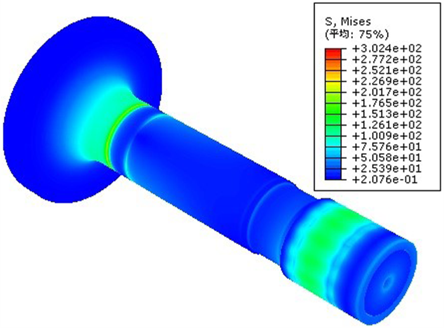
The stress distributions of the main shaft (MPa).

The internal stress distributions of the main shaft (MPa).
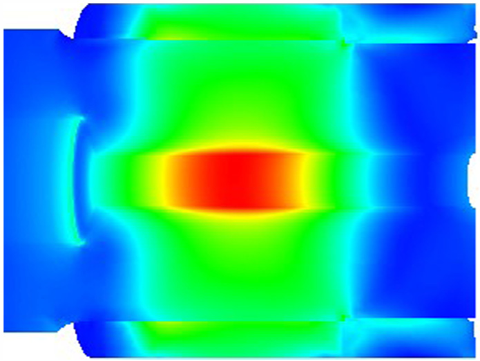
Magnified view of the internal stress distributions of the main shaft tail (MPa).
In contrast to the analyzed results in section 2.3.2, after redesigning the main shaft structure, the stress at the region affected by the bulging joining sleeve decreased significantly from about 441.3 to 302.4 MPa; especially, the stress at the variable radius section at the end of the main shaft decreased from 304 to 94.7 MPa.
By means of structure improvement, the stress concentrations in the main shaft have been improved, which can decrease crack initiation and extension effectively.
Conclusion
Based on the mechanical property test, the impact property at low temperature and the hardness of the main shaft are insufficient, which indicate the potential influence from the fracture mechanics point of view. Based on the FEM analysis, the stress concentrations of the main shaft result in the generation of fatigue sources, which is in good agreement with the analysis results of Aleksandra et al. 27 Based on the results of discrete models of the main shaft for strength analysis, structure improvement of the main shaft was carried out. The simulation result shows the improvement of moving the variable radius section is effective. This article provides a reference for shaft fracture analysis and these results provide technical support for improvement in the design of wind turbine main shafts. It seems justified to perform further works and analyses in order to evaluate the potential lifetime extension of the main shaft.
Footnotes
Handling Editor: Shun-Peng Zhu
Declaration of conflicting interests
The author(s) declared no potential conflicts of interest with respect to the research, authorship, and/or publication of this article.
Funding
The author(s) received no financial support for the research, authorship, and/or publication of this article.