
Abstract
With the increasing mining depths of underground coal mines, gas drainage and coal permeability improvement with conventional coal seam fracture stimulating methods have shown some deficiencies. In this work, an application of liquid CO2 gasification blasting is proposed for increasing gas drainage and fracturing coal seam with high-gas content and low permeability. The methods of theoretical analysis, numerical simulation as well as field experiments are involved to build up a comprehensive understanding of this promising application. The variation of gas pressure for the gasification blasting is quantitatively determined by using a modified van der Waals equation of state. It is shown that the maximum pressure generated by the rapid thermal expansion of liquid CO2 could induce the initiation and propagation of coal cracks and fractures. To testify the fracturing effects of liquid CO2 gasification blasting on gas drainage, field experiments were carried out on two transportation roadways of Yuwu coal mine in China. It is found that (a) the effective fracturing radius could be about 3 m around the blasting borehole, (b) the quantities of gas extraction and gas emission are increased significantly, and (c) the outburst risk indices for drilling cutting fall below their critical values.
Introduction
As China’s primary energy supply, coal has played a leading role in supporting the country’s energy needs for the long term. Meanwhile, coal mine gas (also known as coalbed methane) has increasingly become an important source of energy in China. 1 On the other hand, coal and gas outburst, which is recognized worldwide as one of the potentially fatal hazards during coal mining, caused tens of billions dollars in property damage and killed hundreds of people each year. 2 In particular, with the depletion of shallow coal resources, the mining depths of some coal mines have reached between 800 and 1200 m where the gas pressure and gas content can reach 6 MPa and 22 m3/t, respectively. 3 In such coal seams, mining activities will risk more gas hazards. As a result, gas drainage has been the most common technique for gas management before mining soft coal seams with high-gas pressure and low permeability. 4
Currently, several technical methods have been proposed by researchers to improve the coal permeability and increase gas drainage, mainly including destress blasting, 5 hydraulic fracturing,6–8 and high-pressure waterjets.9,10 However, due to the complex influencing factors such as geological structure, mining depth, seam thickness, and the mode of operation, 11 all these methods have certain limitations. For example, drilling dense and extensive in-seam boreholes for gas drainage in low-permeability coal seams is not affordable. 10 Explosive blasting in gassy coal mines has safety risk, and it is extremely troublesome to deal with unexploded dynamite. 12 Hydraulic fracturing may cause local stress concentrations to induce earthquakes. 13 Furthermore, the cracks of hydraulic fracturing are created randomly and are generally affected by the in situ geostress conditions. 7 In addition, drilling in soft coal seams often suffers from borehole collapse, drill clamping, and sticking. 14
In recent years, hydraulic fracturing with non-aqueous fracturing fluids has been given a high priority for industry and concerned environmental groups. Middleton et al. 15 reviewed the opportunities and challenges for non-aqueous fracturing technique with supercritical CO2. Ishida et al. 16 conducted hydraulic fracturing experiments with supercritical and liquid CO2. Besides, Li et al. 17 proposed the liquid N2 gasification fracturing technology for shale gas development. Although the non-aqueous fracturing technique has an encouraging prospect for applications in unconventional shale gas, 18 it is difficult to practice in underground coal mine for fracturing coal seam. This is because under the influence of mining and excavation activities, gas pressure in borehole can hardly be kept at a high enough value due to the air leakage.
However, incorporating the advantage of non-aqueous fracturing into that of explosive blasting, liquid CO2 gasification blasting seems to be an applicable method for underground coal mine. The CO2 gasification blasting utilizes the release of CO2 phase-change energy to produce a large blasting power that acts on coal body and effectively creates fractures in the coal seam. 19 Currently, the Cardox system is such a product, but it was originally designed for breaking hard materials. 20 The Cardox system became extensively used during the early 1950s. In 1989, it was introduced into licensed coal mines in South Wales and recently was successfully used on a shaft sinking project in granite rock. 21 This method has potential advantages over traditional methods, such as no spark exposure, controllable bursting pressure, and smaller costs. 21 Till now, studies on liquid CO2 gasification blasting and its applications for fracturing coal seams are far less fruitful.
In this study, we propose the application of liquid CO2 gasification blasting for improving coal permeability and increasing gas drainage while driving coal roadways in a high-gas low-permeability single coal seam. The experimental system is introduced, and fundamental mechanisms are described by using theoretical calculation and numerical simulation. To evaluate its effects, field experiments are conducted at the heading faces of two transportation roadways in Yuwu coal mine of China.
Experimental system and fundamental mechanisms
Main components
Liquid CO2 gasification blasting system used in underground coal mines consists of blasting tubes and handling system, as shown in Figure 1. The blasting tube is redesigned on the basis of conventional Cardox system. Its main body is a reusable, high-strength alloy steel tube, which is charged with liquid CO2 and equipped with a chemical energizer, a rupture disc, and a discharge head, as shown in Figure 1(b). The chemical energizer is used to heat the liquid CO2, which is initiated by a small electrical charge. The discharge head at the end of the blasting tube is used to release high-energy CO2 when the blasting tube is detonated remotely. The rupture disc serves as a safety valve, that is, when the pressure in the tube is greater than its tensile strength, a shear failure of the rupture disc occurs. After detonation, the blasting tube can be recharged for another use. In our experimental system, each tube with the length of 2 m and the diameter of 74 mm is charged with 2 kg liquid CO2, and 20 tubes in series are used for one blasting. Furthermore, a handling system which consists of drilling rig, drilling pipe, water pump, and borehole sealing is designed to deliver the blasting tubes to desirable operation sites in the coal seam. A borehole with the diameter of 84 mm and the depth of 60 m is drilled to fix the blasting tubes. Then, the drilling pipes equipped with electric wire are connected to blasting tubes in order to remotely initiate the chemical energizer. Water at high enough pressure is injected into two separate packers by using the water pump to seal the borehole, as shown in Figure 1(a). The sealing length between two packers is at least 10 m for safety reasons.

The schematic diagrams of (a) the liquid CO2 gasification blasting system, (b) the blasting tube, and (c) the photos of experimental setup.
Dynamical process
When initiated by a small electrical charge, the chemical energizer begins a reaction that generates enough heat within milliseconds so that the pressure and temperature will increase quickly. The variation of CO2 pressure in the whole blasting process is shown in Figure 2. It can be seen that the dynamical process can be divided into three different stages: rapidly rising stage (A to B), rapidly falling stage (B to C), and slowly falling stage (C to D). Since the critical pressure pcr and temperature Tcr are about 7.38 MPa and 31.1°C, CO2 undergoes a phase transition from liquid state to supercritical state and then gaseous state.

The evolution of CO2 pressure with time in the whole process of gasification blasting.
The stage of A → B
Initially, liquid CO2 with the pressure of about 8 MPa is filled into the cartridge, that is, pA = 8.0 MPa. Then, due to the reaction heat of chemical energizer, the pressure rises rapidly up to the maximum at the point B where the failure of rupture disc occurs. The following modified van der Waals equation of state for high-pressure and high-density gas is used to estimate the maximum pressure pB 22

where p is the pressure, V is the volume, T is the temperature, R is the universal gas constant, and a, b, and c are modified parameters, respectively. Equation (1) has taken into account the intermolecular attraction, molecular volume, and volume compression of molecules under the high-pressure condition, so it can be reasonably applied to supercritical fluids as a preliminary estimate.
Due to the existence of inflection point on the critical isotherm, equation (1) has the following properties

where Tcr, pcr, and Vcr denote the critical temperature, pressure, and volume, respectively. Substituting the solutions of a, b, and c obtained from equation (2) into equation (1) yields

where pR, VR, and TR are defined as pR = p/pcr, VR = V/Vcr, and TR=T/Tcr, respectively. γ=c/Vcr, and Zcr is the critical compressibility factor with Zcr=3/8 (1+γ).
Considering the fact that the second term on the left-hand side of equation (1) which is produced by intermolecular attraction decreases with the increase of temperature, it can be assumed that the parameter a is inversely proportional to temperature. Consequently, equation (3) can be modified as

Since the volume of CO2 does not change in the process of A to B, VR = VB/Vcr = VA/Vcr = ρcr/ρA. With ρA = 705.8 kg/m3 at TA = 25°C and ρcr = 463.9 kg/m3 at Tcr = 31°C , it can be obtained that VR = 0.657 and equation (4) is reduced to the following form

From equation (5), it can be concluded that when the chemical energizer generates enough heat so that TR is greater than 6, the pressure pB will exceed 270 MPa. The practical value of pB is controlled by the tensile strength of rupture disc. This is because the rupture disc serves as a safety valve. When the blasting is initiated by the chemical energizer, gas pressure increases rapidly. However, once the gas pressure in the CO2 chamber exceeds the tensile strength of rupture disc, a shear failure of the rupture disc occurs. Then, gas will quickly enter into the discharge head and borehole. Meanwhile, gas pressure is relieved. So the maximum gas pressure pB will not exceed the tensile strength of rupture disc.
The stage of B → C
At the point B, the failure of rupture disc occurs, and the supercritical CO2 expands into the discharge head, whereafter CO2 spurts out from the ports of discharge head at the point C. Since this stage occurs within milliseconds, it can be assumed that the temperature in the cartridge remains unchanged. Equation (4) can still be used to estimate the pressure at the point C. The length and diameter of discharge head are 36 cm and 74 mm, respectively, so the value of VR at the point C is approximated as VR = 1. Then, equation (4) is simplified as

If TR is equal to 6, the pressure pC can reach 170 MPa, which is by far greater than the strength of coal mass.
The stage of C → D
In this stage, the expanding gas enters into the whole borehole and then penetrates into the cracks created by the former stage. Meanwhile, the pressure decreases gradually until it is balanced with the gas pressure in coal fractures. Due to the preferential adsorption of CO2, it is also expected to displace methane from lower porosity coal matrix during this stage.
Another blasting parameter is the total energy released in the process. Due to the phase transition, it is difficult to determine the exact blasting energy. We assume that the expansion of CO2 is an adiabatic process, following the equation

It can be obtained that E = 2550 kJ for one tube which is equivalent to a load of 0.6 kg trinitrotoluene (TNT).
Fundamental mechanism
Fracture formation
The high pressure exerted on the borehole wall at the moment of blasting could set off stress wave, causing a high strain rate in the coal seam. During the propagation of stress wave, tensile stress or shear stress leads to coal failure in tension or in shear. Shear stress could give rise to a crushed zone around the borehole, while tensile stress could cause radial cracks. 23 The radius of crushed zone can be determined as 24

where rc and r denote the radii of crushed zone and borehole, respectively. pmax is the maximum gas pressure, Kc is the dynamic compressive strength coefficient of coal, σc is the uniaxial compressive strength of coal, and µ is the dynamic Poisson’s ratio of coal.
The rapid decay of high-amplitude stress wave is followed by the gas pressure loading with a longer duration. The gas pressure loading may expand those cracks created artificially, and the fissures and micro-fractures formed naturally in the coal seam. Due to the initiation and propagation of blasting-induced coal fractures, the permeability of coal seam increased significantly. The effective fracturing radius can be estimated as 24

where rf denotes the fracturing radius, Kt is the dynamic tensile strength coefficient of coal, σt is the static tensile strength of coal, and b is the lateral stress coefficient.
Destress blasting
Since the heterogeneous distribution of stress field is an important factor to trigger coal and gas outburst, the resultant stress concentration should be eliminated or alleviated during coal mining. Liquid CO2 gasification blasting can alter the structure of coal mass by creating fracture network in the coal seam, thus effectively reducing the coal strength. Moreover, the blasting-induced damage can loosen the coal seam around the blasting borehole, which shifts the stress concentration zone away from the active area and leaves a protective barrier between the heading face and the stress concentration zone.
The coal permeability is stress-dependent and evolves exponentially with increasing net confining stress (confining pressure minus average flowing fluid pressure) in the following form 25

where k0 is the coal permeability at the reference pressure p0 and confining stress σ0. Cf is the cleat volume compressibility, and Δσ = σ−σ0 is the change in the net confining stress.
Numerical simulation
Mathematical model
Deformation equations of coal seam
For a homogeneous, isotropic and elastic medium, the constitutive relation between stress σ and strain ε is expressed as

where G is the shear modulus and ν is Poisson’s ratio.
The Navier equation for displacement u is given by

where fi is the body force in the ith direction.
The displacement and stress conditions on the boundary are given as

where ũ and
Dynamic damage constitutive relation
Generally, the non-linearity of stress–strain relation of coal and rock is caused by the initiation and propagation of cracks and micro-fractures rather than the plastic deformation. The elastic damage constitutive relation can be used to characterize the mesoscopic element of coal mass. Based on the criteria of maximum tensile stress and Mohr-Coulomb failure, tensile and shear damage occur when the following conditions are satisfied, respectively
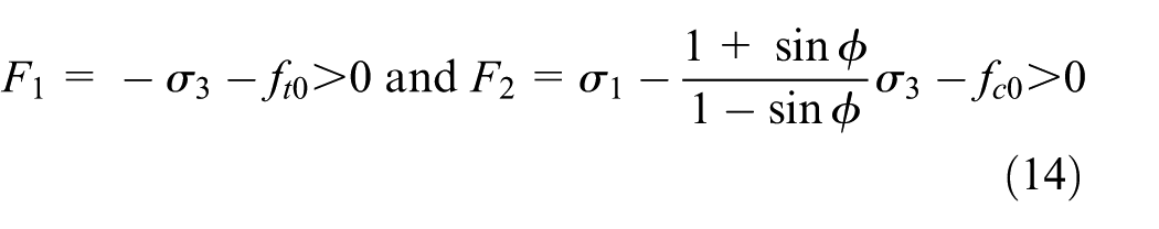
where ft0 is the uniaxial tensile strength and fc0 is the uniaxial compressible strength, as shown in Figure 3.

The stress–strain relation under the uniaxial stress condition. 26
The elastic modulus of element is given as

where E is the elastic modulus before damage, and D is the damage variable defined by

Numerical model and method
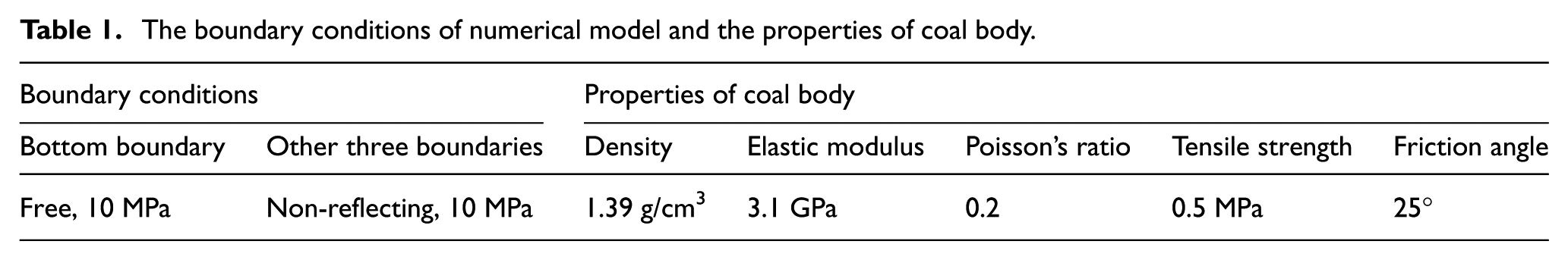
Figure 4(a) shows the two-dimensional numerical model of simulated coal seam. The size of coal seam is 3.6 m × 5.0 m in height and width, and a borehole with a diameter of 84 mm is located at the middle of horizontal direction and at a distance of 1.5 m from the bottom. Figure 4(b) shows the mesh of numerical model in which the total number of elements is 10,114, and the mesh has been found to be fine enough. The bottom boundary is set as a free face, and other three boundaries are non-reflecting faces, as shown in Figure 4(a). The boundary conditions for loading stress on the free and non-reflecting faces are PL = 10 MPa. The parameters for pressure wave at the borehole surface are p0 = 170 MPa and t0 = 100 μs. Other parameters for numerical simulation are shown in Table 1. In addition, the heterogeneity of coal mass is characterized by Weibull distribution.

(a) The numerical model and (b) corresponding mesh of simulated coal seam.
The boundary conditions of numerical model and the properties of coal body.
In this work, the mathematical model together with above boundary conditions is solved by COMSOL Multiphysics with MATLAB. The COMSOL software is a powerful Finite Element Method (FEM)–based commercial software package, which can directly solve partial differential equations with initial-boundary conditions, and has been successfully applied in the study of fracture formation. 27 The deformation equations for coal seam are implemented by the Solid Mechanics module of COMSOL, and the damage criterion is checked by MATLAB. The entire numerical iteration is carried out through COMSOL with MATLAB. The computational process has three steps. First, the coal deformation is solved for given boundary conditions and parameters. Second, the results from the first step are used in the damage criterion to judge the occurrence of element failure. Third, the computational procedure is ended if the damage criterion is satisfied. Otherwise, the boundary conditions are updated, and the procedure returns to the first step. The multiple loop iteration is done until no element failure occurs.
As a load applied on the model, gas pressure shown in Figure 2 should have two effects on the numerical simulation: instantaneous high pressure on the surface of borehole and expanding gas in the cracks of coal seam. The former effect is taken into account in such a way that a pressure wave is applied on the boundary of borehole with peak pressure p0 = 170 MPa and rising time t0 = 100 μs. The latter effect is not considered in the numerical simulation because the change of gas pressure with time in the coal seam cannot be quantitatively obtained.
Stress wave propagation and damage distributions
In Figure 5, it is shown that the stress wave spreads around from the center of blasting source, and its intensity attenuates with the radial distance. When the compressive stress wave strikes the free face, it is reflected backward to produce a tensile stress wave, as indicated in Figure 5(d). If the reflected tensile wave is sufficiently strong, circumferential cracks could be initiated. Therefore, the free faces can centralize the blasting energy and improve the fracturing effect.

The distributions of first principal stress for different time: (a) t = 200 µs, (b) t = 400 µs, (c) t = 800 µs, and (d) t = 1200 µs.
Due to the stress wave loading, a damage zone will appear around the blasting borehole. Meanwhile, with the propagation of stress wave, the blasting energy transfers outward and the damage zone is gradually extended. When the compressive stress wave strikes the free face, another damage zone is formed near the free face. The damage distributions corresponding to Figure 5(d) are illustrated in Figure 6(a). As a comparison, the case of four controlling holes drilled around the blasting borehole is also simulated, as shown in Figure 6(b). The purpose of controlling holes is to artificially create free faces. Obviously, the damage zone with controlling holes is greater than that without controlling holes.

The damage distributions at t = 1200 µs with (a) no controlling holes and (b) four controlling holes around the blasting borehole.
Field experiments
Field experiments are carried out to comprehensively testify the effects of liquid CO2 gasification blasting on increasing coal permeability and improving gas drainage while driving coal roadways.
Introduction of testing sites
As parts of the Qinshui Coalfield, Yuwu coal mine is located in Changzhi City, Shanxi Province of China, as shown in Figure 7. The mining area is 160.24 km2 and divided into six panels with two in the north and the rest in the south. The primary minable coal seam is #3 with an average buried depth of 440 m. Furthermore, this coal seam has poor gas drainage due to its low permeability, and risks coal and gas outburst.

The location of Yuwu coal mine in China.
In our study, the S2108 and N1101 transportation coal roadways are chosen as the experiment sites. Their cross-sections are rectangular with the width of 5.4 m and the height of 3.8 m, and the designed length of two roadways is 1351 and 2489 m, respectively. The original gas content is 9.50 and 9.75 m3/t, and the thickness of coal seam is 6.15 and 6.34 m, respectively. Liquid CO2 gasification blasting is conducted once every 50 m in the middle of heading faces, where release holes are drilled for gas emission. Meanwhile, drilling fields are constructed at both sides of coal roadways for gas extraction, the cross-section of which is trapezoidal with the height of 3.8 m. The layout of coal roadway and drilling fields is shown in Figure 8(a).

The layout of blasting and testing boreholes for the field experiments: (a) the sectional view of coal roadway, (b) the scheme for gas composition analysis, (c) the scheme for microseismic event detection, and (d) the scheme for drilling indices measurement.
Testing methods
Analysis of gas composition in monitoring boreholes
If certain regions surrounding the blasting borehole are fractured by the gasification blasting, the coal permeability of this region will be significantly increased and CO2 released from blasting tubes could flow into the fractures. Then, CO2 concentration in this region will be greater than other regions. Therefore, by analyzing gas composition in the monitoring boreholes with different distances from the blasting borehole, the effective fracturing radius rf of gasification blasting can be determined.
Based on the above principle, the field experiment was carried out at the heading face of S2108 roadway. The experiment scheme is shown in Figure 8(b), where the monitoring boreholes C1, C2, C3, C4, and C5 were drilled in advance with the diameter of 42 mm and the length of 25 m. After blasting, plastic tubes with the length of 5 m were inserted into these monitoring boreholes to collect the emitted gas. The operation method is as follows: (a) plastic tubes with a length of 5 m were inserted into these monitoring boreholes, (b) water at high enough pressure is injected into a hole packer by using the water pump (as shown in Figure 1(c)) to seal the borehole, (c) the end of the plastic tube is sealed by coal slime, (d) a syringe is used to extract gas from the plastic tube, and (e) the gas is immediately injected into gas collecting bag and brought back to the laboratory. Finally, the gas composition in each borehole was analyzed by the gas chromatograph. It is noted that the roadway air has no effect on the gas composition in the monitoring boreholes because the monitoring boreholes are sealed by hole packers in advance.
Detection of microseismic events
The process of coal seam deformation and failure will generate elastic wave and release energy, which could set off microseism. In the literature, it has been found that coal seam deformation and failure can be analyzed by microseismic effect.28–30 The location of microseismic source (failure points) is based on the difference in time at which each probe receives the microseismic events. The parameters for characterizing microseismic events include the amplitude of voltage, energy, and frequency of electromagnetic signals received by the probes of microseismograph. In this work, during the process of liquid CO2 gasification blasting, microseism occurs due to the initiation and propagation of naturally preexisting or artificially created fractures. Microseismic events can be monitored by the installation of probes at the heading surface, and the amplitude of voltage is used to characterize the microseismic events. Based on the monitoring data of the amplitude of voltage, the microseismic source can be located by using classical inversion algorithms in the geophysics, such as enumerative method, Monte Carlo Method, and Lipschitz method.31,32
The on-site microseismic monitoring was conducted at the heading face of N1101 roadway. The experiment scheme is shown in Figure 8(c), where P1, P2, P3, P4, and P5 are monitoring probes of the microseismograph. Microseismic data acquisition lasted 30 min after blasting. Microseismic source location is achieved by classical enumeration algorithm and grid search method.
Measurement of gas drainage and gas emission
The quantities of gas extraction from the drilling fields and gas emission from the heading face were monitored by arranging sensors. The gas emission from single borehole was also measured. As shown in Figure 8(d), M1 and M2 were drilled after and before blasting, respectively. The volume of gas emission from the two boreholes was measured for 5 min.
Measurement of outburst risk indices
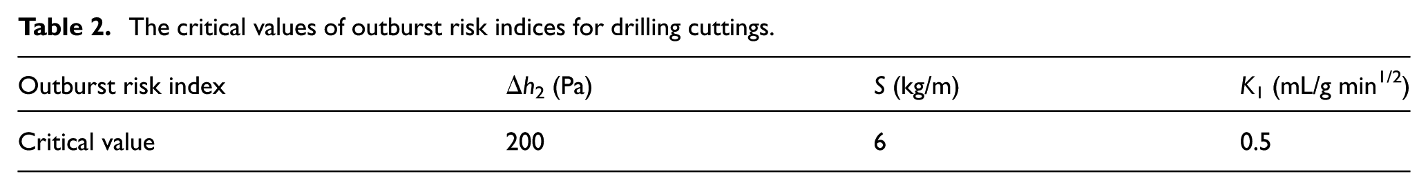
Drilling indices of outburst prediction are measured, mainly including drilling cutting quantity S, gas desorption index Δh2, and K1, the critical values of which are listed in Table 2. The parameter Δh2 indicates the pressure difference created by the gas desorption of drilling samples at the initial stage, and the parameter K1 is the slope of gas desorption curve. The parameter S is the quantity of drilling cutting per meter when drilling a borehole, which is related to the earth stress field and the damage degree of coal structure.
The critical values of outburst risk indices for drilling cuttings.
The measurement of drilling cutting quantity S was conducted once at the heading face of S2108 roadway, while gas desorption indices Δh2 and K1 were measured once at the heading face of S2108 roadway and twice at the heading face of N1101 roadway. The experiment scheme is shown in Figure 8(d), where M1, M2, M3, M4, and M5 are measuring boreholes with the diameter of 42 mm. According to the regulations of State Administration of Work Safety, 33 drilling cuttings should be taken every 2 m in each borehole. As for the indices Δh2 and K1, a 10 g drilling sample with the grain size between 1 and 3 mm is used, and the time for gas desorption is 2 min.
Results and discussion
Determination of effective fracturing radius
The main gas compositions in five different boreholes as shown in Figure 8(b) are listed in Table 3, and the changes of CH4 and CO2 concentration in terms of volume percentage are plotted in Figure 9. It is easily understood that CH4 desorbed from coal matrix flows into the boreholes so that the volume percentage of CH4 in all monitoring boreholes keeps relatively high values, varying from 93.8% to 96.6%. However, the volume percentage of CO2 declines rapidly with the distance from the blasting borehole. The maximum concentration of 0.162% appears in the nearest borehole, while CO2 is hardly detected in the farthest borehole. It can be explained as follows. After blasting, a fracturing zone with a large amount of cracks and fractures is formed near the blasting borehole, so CO2 in the blasting borehole can penetrate into adjacent regions such as C1, C2, and C3, resulting in that a certain percentage of CO2 appears in these three boreholes. Furthermore, the greater the distance from the blasting borehole becomes, the less the quantity of CO2 penetrates. The structure of coal seam at some place far away from the blasting borehole is not affected by the blasting, so no CO2 will be detected in those boreholes, such as C4 and C5. From the variation tendency of CO2 concentration in Figure 9, it can be estimated that the effective fracturing radius of liquid CO2 gasification blasting, rf, should be 3 m or so.
The gas compositions in monitoring boreholes with different distances from the blasting borehole.

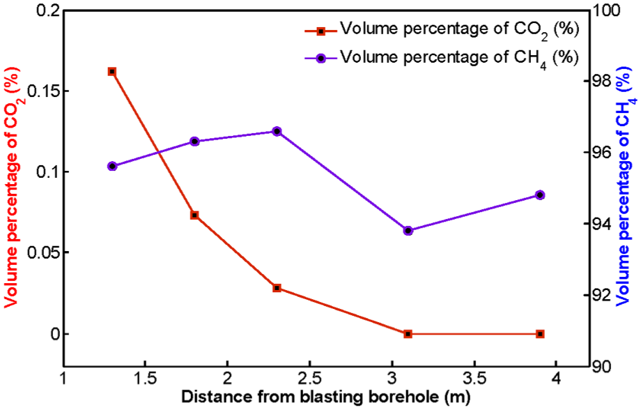
The changes of CO2 and CH4 concentration with the distance from the blasting borehole.
The effective fracturing radius is also confirmed by the microseismic detection. Typical microseismic events monitored in five boreholes during the experiment process are shown in Figure 10(a), where the abscissa denotes time, every small division represents 50 ms, and the total time shown in the abscissa is 3 s. In this figure, the first event is the microseism caused by the detonation of blasting tubes, and the subsequent events may be induced by the damage deformation and fracture propagation of coal mass. It can be seen that within a very short time, a large number of microseismic events occur, implying the significant fracturing effects of liquid CO2 gasification blasting. Based on the field data, microseismic sources are located by using an inversion algorithm as shown in Figure 10(b), where every small division represents 2 m. It is found that the effective fracturing radius in terms of microseismic source location is about 4 m. Furthermore, the microseismic source distributes more densely in the horizontal direction than that in the vertical direction. This is because the fracture formation may be affected by the earth stress field, free surfaces, and joint planes, which leads to non-uniformity in the fracture pattern.

(a) The microseismic events received by five monitoring probes of the microseismograph and (b) the three-dimensional view of located microseismic source.
In addition, the effective fracturing radius can be estimated by virtue of equations (8) and (9). In our calculation, the maximum pressure is produced by the gasification blasting, pmax = 170 MPa; the dynamic compressive strength coefficient, Kc = 10; the uniaxial compressive strength, σc = 4 MPa; the radius of blasting borehole, r = 0.084 m; the dynamic Poisson’s ratio, α = 0.2; and the dynamic tensile strength coefficient, Kt = 1. Substituting these values into equation (8), it is found that the radius of crushed zone rc = 0.16 m. Then, from equation (9), the effective fracturing radius is determined as rf = 2.6 m.
It can be seen that the result obtained by the theoretical calculation shows a good qualitative agreement with those results obtained by field experiments. The cross-section of the heading face is 3.6 m × 5 m in height and width, so 3 m influential radius is good enough for heading development.
The effects of CO2 gasification blasting on gas extraction and gas emission
Gas extraction in the drilling fields and gas emission with release holes at the heading face were performed simultaneously in order to reduce the residual gas content and gas pressure in the target coal seam. Here, release holes refer to the boreholes drilled in the heading face, from which the gas can be naturally emitted into the heading roadway. Liquid CO2 gasification blasting can increase the coal permeability, so that more desorbed gas flows through the fractures and is eventually emitted on the heading face or extracted by the drilling fields.
The gas emission from single borehole before and after blasting is compared, as shown in Table 4. The borehole depth is 12 m with the sealing length of 10 m, and the borehole diameter is 42 mm. It can be seen that before blasting, the total volume of gas emission from single borehole within 5 min is 10.56 L, which means that the average gas emission rate is 2.11 L/min. In sharp contrast, after blasting the total volume of gas emission from single borehole within 5 min is 21.28 L, and the average gas emission rate is 4.26 L/min. Obviously, the gas emission rate from single borehole is almost doubled by performing the gasification blasting. The improvement of gas drainage by liquid CO2 gasification blasting was also reported by other researchers. Zhou et al. 34 found that the average gas concentration of a single borehole increased by 56.4%. More recently, in combination with numerical simulation and field tests, Chen et al. 35 found that the permeability of damaged area of coal seam was set to six times larger than that of the original coal body area.
The volume of gas emission from single borehole at the heading face of S2108 roadway.

The temporal evolutions of the quantity of gas extraction by the drilling fields and gas concentration in the ventilation of heading faces are plotted in Figures 11 and 12, where the airflow rates for N1101 and S2108 roadways are 1560 and 1422 m3/min, respectively. The smoothed lines are obtained by the method of polynomial fitting by using the raw data. The quantity of gas emission on the heading face can be calculated by the product of airflow rate and gas concentration. As shown in Figure 11, when the first blasting was performed, a sudden enhancement of the quantity of gas extraction in the drilling fields appeared, increasing from 7.8 m3/min to the maximum of 8.8 m3/min. Meanwhile, gas concentration in the ventilation increased simultaneously from 0.55% to the maximum of 0.74%. Once the roadway excavation passed through the influence range of gasification blasting after 10 driving days, the quantity of gas extraction and gas concentration dropped to the level before blasting. When the second blasting was carried out, a similar process was reproduced. The comparison indicates that liquid CO2 gasification blasting can significantly increase the quantity of gas extraction and gas emission during the roadway excavation, thus reducing the residual gas content and gas pressure in gassy coal seam. Furthermore, the variations of gas drainage and emission with time for the coal roadway S2108 as shown in Figure 12 are qualitatively similar to the case for the coal roadway N1101 as shown in Figure 11.

The gas drainage and gas emission for the N1101 heading face: (a) the amount of gas drainage from the drilling fields and (b) the gas concentration in the ventilation of heading face.

The gas drainage and gas emission for the S2108 heading face: (a) the amount of gas drainage from the drilling fields and (b) the gas concentration in the ventilation of heading face.
The effects of CO2 gasification blasting on coal and gas outburst risk
The changes of Δh2 with drilling depth in five different sampling boreholes are shown in Figure 13(a). For comparison, M1, M2, and M3 are measured before blasting, while M4 and M5 are measured immediately after blasting. The measured values of Δh2 for the first three points are all below their critical value, and their differences shown in Figure 13(a) are small. However, when the drilling depth of the measuring boreholes is larger than 10 m, Δh2 increases rapidly with the increase of drilling depth. This is because the larger the drilling depth is, the closer the residual gas content, and gas pressure approximates to the original gas content and gas pressure, and the more gas is desorbed from the coal matrix. More importantly, the values of Δh2 for M4 and M5 are obviously greater than those for M1, M2, and M3, due to the fact that the gasification blasting induces a large number of small cracks and fractures in the coal matrix, which provide more paths for gas desorption.

(a) The changes of Δh2 with drilling depth of sampling boreholes at the heading face of N1101 roadway, (b) the changes of Δh2 for different drivage length of S2108 roadway, and (c) the changes of Δh2 for different drivage length of N1101 roadway.
The changes of Δh2 for different drivage length of S2108 and N1101 roadways are shown in Figure 13(b) and (c), where the data before blasting were measured in the borehole M1 and the data after blasting were measured in the borehole M4. It can be found that the values of Δh2 decline rapidly with drivage length and driving days, which could be caused by the gas extraction and gas emission during the roadway excavation. In addition, the values of Δh2 fall below its critical value for the whole drilling depth 3 days after the blasting.
The drilling cutting quantity S per meter is shown in Figure 14(a). It can be seen that with the increasing drilling depth, S has an increasing tendency as a whole, but its maximum is far below its critical value. The change of gas desorption index K1 with driving days is shown in Figure 14(b). It can be observed that before blasting, the value of K1 fluctuates in the neighborhood of 0.43 mL/g min1/2. After blasting, the value of K1 decreases to a lower level in the neighborhood of 0.37 mL/g min1/2. When the roadway excavation passes through the influence range of gasification blasting after 10 driving days, the value of K1 recovers to the level before blasting, indicating the significant effect of gasification blasting on gas desorption characteristics.

(a) The drilling cutting quantity S in different sampling boreholes after blasting for S2108 roadway and (b) the change of K1 with driving days for N1101 roadway.
The effects of CO2 gasification blasting on driving efficiency of coal roadway
With the reduction of residual gas content and gas pressure in the heading face, coal and gas outburst risk is reduced, and the efficiency of roadway excavation in gassy coal seam is also improved significantly. The daily drivage length of N1101 roadway after performing the gasification blasting was recorded, as shown in Figure 15. It can be seen that apart from the first day, the minimum and maximum lengths of daily roadway drivage reached 5.0 and 7.2 m, respectively. The average driving speed reached 5.7 m per day. According the records of coal mine, the average speed with the traditional technique of explosive blasting has only 3.5 m per day. Furthermore, no dynamic phenomenon happened while driving the S2108 and N1101 transportation roadways.
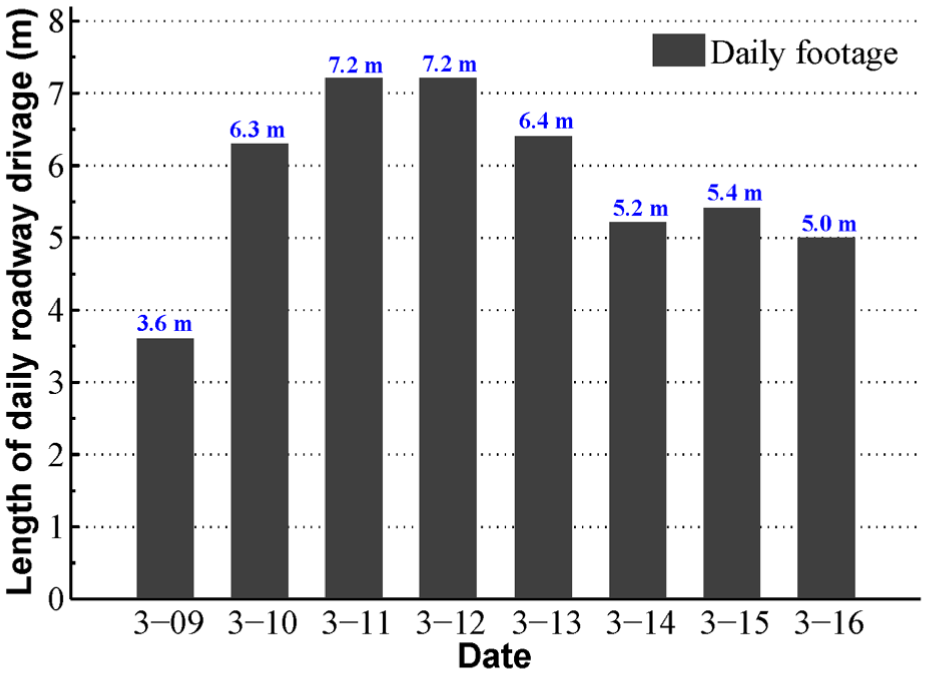
The length of daily drivage for N1101 transportation roadway.
Conclusion
The objective of this work is to investigate the effects of liquid CO2 gasification blasting on improving coal permeability and increasing gas drainage while driving coal roadway. We introduce the experimental system, analyze the fundamental mechanisms, and evaluate the blasting effects. First, based on a modified van der Waals equation of state, the pressures generated by thermal expansion of gas for different dynamical stages are calculated. Then, it is theorized that the gasification blasting plays dual roles through two coupled processes, including blasting-induced coal fractures for increasing coal permeability and blasting-induced damage for eliminating stress concentration. Third, the propagation of stress wave and the development of damage failure are simulated with FEM. Finally, field experiments were carried out on two transportation roadways of Yuwu coal mine in China. The effective fracturing radius was estimated to be about 3 m around the blasting borehole. After performing the gasification blasting, there was an obvious increase in the quantity of gas emission from the heading face and gas extraction from the drilling fields. In addition, the outburst risk indices fell below their critical values, no gas hazards happened while driving the transportation roadways, and the average driving speed achieves 5.7 m per day.
Footnotes
Handling Editor: ZW Zhong
Declaration of conflicting interests
The author(s) declared no potential conflicts of interest with respect to the research, authorship, and/or publication of this article.
Funding
The author(s) disclosed receipt of the following financial support for the research, authorship, and/or publication of this article: This work was supported by the Fundamental Research Funds for the Central Universities (Grant No. 2017XKQY025), the Program for Changjiang Scholars and Innovative Research Team in University (Grant No. IRT_17R103), and the Priority Academic Program Development of Jiangsu Higher Education Institutions (PAPD).