
Abstract
This article deals with the development and performance characterisation of model-based health monitoring algorithms for the detection of faults in an electromechanical actuator for unmanned aerial system flight controls. Two real-time executable position-tracking algorithms, based on predictors with different levels of complexity, are developed and compared in terms of false alarm rejection and fault detection capabilities, using a high-fidelity model of the actuator in which different types of faults are injected. The algorithms’ performances are evaluated by simulating flight manoeuvres with the actuator in normal operation as well as with relevant faults (motor coil faults, motor magnet degradation, voltage supply decrease). The results demonstrate that an accurate position-tracking monitor allows to obtain a prompt fault detection and fail-safe mode engagement, while more detailed monitoring functions can be used for fault isolation only.
Keywords
Introduction
Electromechanical actuators are nowadays the reference technology for unmanned aerial systems (UAS) flight controls, but their applicability, though proved in terms of load, speed and dynamic performances,1–3 still entails several concerns in terms of reliability. The electromechanical technology enhances the maintainability of flight control systems (thanks to the elimination of hydraulic power lines), but also requires a cautious approach to safety, mainly for the lack of a statistical database about components’ fault modes.4,5 This drawback is typically counteracted using redundant architectures, so that fail-operative and/or fail-safe actuators are obtained.6–9 The number and the type of redundancies applied within the actuator clearly depend on its target reliability, which in turn depends on the whole flight control system architecture. For example, the split of flight controls into independent subsurfaces, each driven by a dedicated actuator, allows to simplify the actuator architecture in terms of mechanical and electrical redundancies. In this context, the design of health monitoring algorithms implementing fault detection and isolation (FDI) functions is a key issue for electromechanical actuators’ development, in order to maintain operability in case of partial failures, or to revert in fail-safe mode in case of total loss of control. Nevertheless, health monitoring implies an increase of complexity of both sensors’ system and control software, so that a strong effort is required for limiting the number of both sensors and algorithms, while preserving satisfactory FDI capabilities. In addition, the design and the validation of the health monitoring algorithms can result in prohibitive costs: since actuator nonlinearities, sensor disturbances and sensitivity to environment and loads can have a strong impact on monitoring performances, an in-depth knowledge of the actuator dynamics is required in both normal condition and with faults. This can be achieved via experimental activities, in which the actuator response is characterised by artificially injecting faults,10–12 but rigging costs can be relevant. An alternative approach, which this article refers to, is to use high-fidelity actuator models that are experimentally validated with reference to the normal condition only, but also capable of simulating the faulty behaviour by physical first principles.13,14
The basic idea underlying this work is that major faults in position-controlled flight controls can be detected by a position-tracking monitor (PTM), provided that an accurate predictor is used.15,16 This would simplify the software complexity as well as the number of additional sensors needed for the health monitoring functions. In this article, starting from the architecture of a fault-tolerant electromechanical actuator for a medium-altitude long-endurance (MALE) UAS (Figure 1), two model-based position-tracking algorithms are developed and compared in terms of performance. Both algorithms are based on dynamic predictors that detect a malfunction when the actual feedback deviates from the prediction for a predefined threshold, but they differ in the estimation of the actuator speed. The false alarm rejection and fault detection capabilities are characterised using a high-fidelity actuator model,17,18 in which relevant faults (motor coil faults, motor magnet degradation, voltage supply decrease) are injected during the simulation of flight manoeuvres.
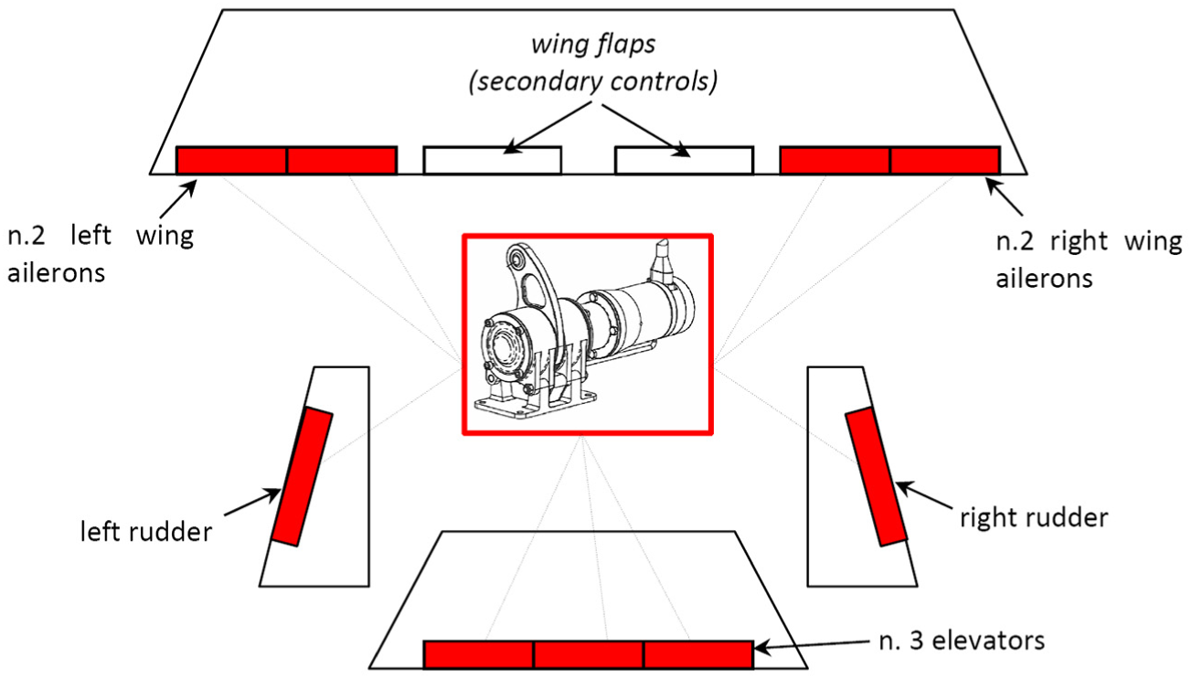
FCS architecture of the reference MALE UAS with EMAS on primary flight controls.
System description
Basic components and actuator control unit
The reference electromechanical actuator system (EMAS) is composed of an actuator control unit (ACU), a 3-phase permanent magnet synchronous motor with sinusoidal modulation and a mechanical transmission made of a two-stage gearbox and an output lever. The ACU includes 16
Two independent computing sections, implementing the health monitoring (MON lane) and closed-loop control (CON lane) functions; 19
A pulse width modulation (PWM) ‘phase-isolating’ drive modulating the motor coil currents, made of three full H-bridges, each dedicated to a coil (12 metal-oxide-semiconductor field-effect transistor (MOSFET) switches in total); 9
A cross-lane data link, for the data exchange between the lanes;
A power supply unit (PSU), providing all ACU modules with the electrical power.
The ACU CON lane, based on digital signal processing (DSP) technology, implements three nested closed-loop controls on the EMAS: on motor currents, on motor speed and on output position. The CON is also able to manage both the EMAS sensor interfaces and the PWM drive of the motor phases. The MON lane is based on an Advanced RISC Machine (ARM) processor, selected to implement hardware dissimilarity with the CON lane. The ARM processor has reduced computing performances when compared with the DSP, but it integrates two processors in lock-step configuration to improve the processor error detection (e.g. bus or memory errors).
Sensors’ system
The EMAS sensor system architecture is schematically shown in Figure 2 and is composed of 16
A supply voltage sensor (SVS), measuring the voltage provided by the aircraft electrical power plant;
A temperature sensor (TS), measuring the PSU temperature;
Six current sensors (CSa1, CSb1, CSc1, CSa2, CSb2, CSc2) mounted in series with the motor phases, measuring the phase currents, three of which used for the closed-loop control and three for the health monitoring functions;
Three voltage sensors (VSa, VSb, VSc) mounted in parallel with the motor phases, measuring the phase voltages, and used for the health monitoring functions;
A resolver (R), integrated in the motor assembly, measuring the motor shaft rotation, and used for the closed-loop control;
Two rotary variable differential transformers (RVDTs; RVDT1 and RVDT2) measuring the output lever rotation, one of which is used for the closed-loop control and the other for the health monitoring functions.

Schematic of the EMAS architecture.
Health monitoring algorithms
As the result of a specific reliability-oriented work by Di Rito et al., 16 the FDI functions for the EMAS are performed by the following set of health monitoring algorithms:
PTM, which predicts, by means of a dynamic model, an expected position response to system inputs, in order to detect overall faults or performance degradations;
Current monitor, which performs a check of the current levels in the motor coils, to detect opened coils and to protect from over-currents;
Cross-lane current monitor, which performs a comparison between the currents measured by the CON and the MON lanes, to detect sensor faults;
In-lane monitors on the RVDTs and resolver, which perform checks of the status of the sensors, to detect component fault;
Cross-lane position monitor, which performs a comparison between the positions measured by the CON and the MON lanes, to detect transducer faults;
Voltage supply monitor, which performs a check of the voltage supply level, to detect a voltage breakdown or a voltage sensor fault;
PSU temperature monitor, which performs a check of the PSU temperature, to detect an abnormal PSU heating or a TS fault;
In-lane CPU monitors, that is, watchdogs for both CON and MON lanes;
Cross-lane voltage demand monitor, which performs a comparison between the voltage demands for PWM calculated by the CON and the MON lanes, to detect CPU and I/O faults.
An efficient management of the algorithms’ outputs is necessary to avoid conflicting indications and/or uncertainties about corrective actions, so that complex logic could result. The proposed solution is to allocate the fault detection capability and the fail-safe mode engagement to the PTM only and to maintain the other ones for fault isolation only. Starting from this idea, two PTM versions have been developed to evaluate the fault detection performances in case of relevant faults.
Design of PTMs
Both PTMs are made of two sections: a time-discrete dynamic predictor estimating the EMAS position and a fault detection logic (FDL) signalling a malfunction when the error between the prediction and the actual feedback exceeds a predefined threshold.
The PTM development has been carried out by pursuing a balance between prediction accuracy and real-time execution requirements.20,21 For this purpose, the predictors’ equations have been obtained from a reduced model of the actuator dynamics 3 and the number of PTM inputs has been limited to position demand, ML-RVDT position feedback and voltage supply level.
FDL
The FDL, identical for both PTM versions and described by the flow chart in Figure 3, receives as input the normalised error between the PTM prediction and the actual position sensed by the ML-RVDT (θaML), as shown in equation (1)

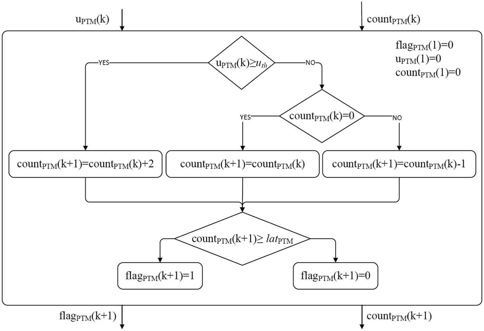
Fault detection logic flow chart (flagPTM = 1 → fault).
As shown in Figure 3, if the normalised error (uPTM) exceeds a predefined threshold (uth), a fault-state counter (countPTM) is incremented by 2, and otherwise there are two cases: if the counter value was different from 0 in the previous step, it is decremented by 1, else it is maintained at 0. If the counter countPTM reaches a maximum threshold (latPTM), the FDL outputs a true boolean signal (flagPTM = 1) and a malfunction is detected.
Predictors’ equations
The two EMAS position predictors have been derived starting from the linear dynamic model described by equations (2)–(6). Equations (2) and (3) reproduce the basic behaviour of a DC motor with a gearbox reducer, 22 while equations (4)–(6) represent the proportional control laws of the three nested regulators of the reference EMAS (on motor current, motor speed and output rotation)
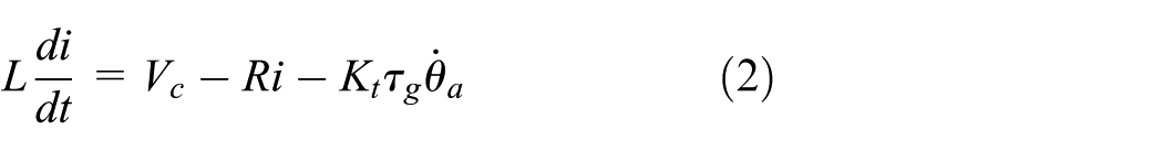


In equations (2) and (3), i is the motor current, θa is the actuator output rotation, Vc is the control voltage, Ta is the external torque, τg is the gearbox ratio and Ja is the output inertia, while Jm, L, R and Kt are the motor inertia, inductance, resistance and back-electromotive force coefficient, respectively. In equations (4)–(6), Ki, Kω and Kθ are the gains of the three proportional regulators, while id, ωmd and θad are the demands of motor current, motor speed and surface deflection, respectively.
Outer loop monitor: first-order predictor
In the first version of the PTM, defined as outer loop monitor (OLM), the prediction is basically obtained by assuming that the speed control loop shows an ideal tracking performance (equation (7))

so that, substituting equation (7) into equation (6), the actuator output speed is given by

where 1/pa can be interpreted as the time constant of a first-order dynamics approximating the EMAS position response.
The OLM includes a time-discrete version of equation (8) and additional conditions to take into account the saturation limits of the output speed, due to the maximal levels of motor voltage and output rotation end strokes. The result is a first-order nonlinear predictor that operates at the sample time TM and implements equations (9)–(12)


In equations (9)–(12), θad and Vs are the deflection demand and the supply voltage (PTM inputs), ωaOLM is the predicted speed and θaOLM, that is, θaPTM (the PTM output), is the predicted position. The OLM predictor is thus characterised by four parameters: the actuator end stroke θaSAT, the voltage supply to motor speed gain Kvω, the actuator speed saturation ωaSAT and the quantity pa defined in equation (8).
Inner loop monitor: second-order predictor
In the second version of the PTM, defined as inner loop monitor (ILM), the prediction is obtained instead by assuming that no external torque is applied (equation (13)) and that the current control loop performs an ideal tracking performance (equation (14))


By substituting equations (13) and (14) into equation (3), we have

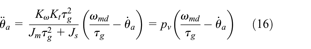
and the actuator output acceleration is finally obtained by
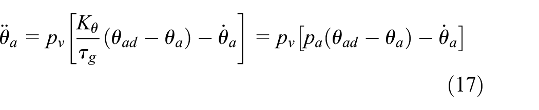
where 1/pv can be interpreted as the time constant of a first-order dynamics approximating the EMAS speed response.
The ILM includes a time-discrete version of equation (17), together with saturation conditions for output acceleration, due to maximal levels of motor currents, output speed and output rotation.
The result is the second-order nonlinear predictor in equations (18)–(23)

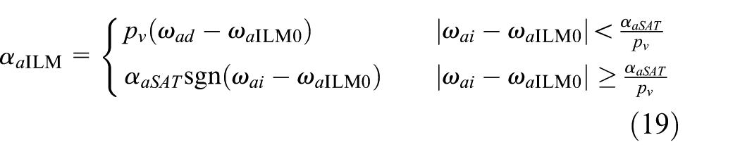

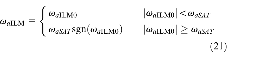
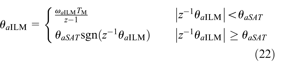

where ωaILM0 is the actuator speed feedback, while αaILM, ωaILM and θaILM (i.e. θaPTM) are the predicted acceleration, speed and position, respectively. The ILM predictor is thus characterised by six parameters: the four ones of the OLM, the actuator acceleration saturation αaSAT and the quantity pv defined in equation (16).
The MATLAB–Simulink implementation of the two PTM versions is presented in Figure 4.
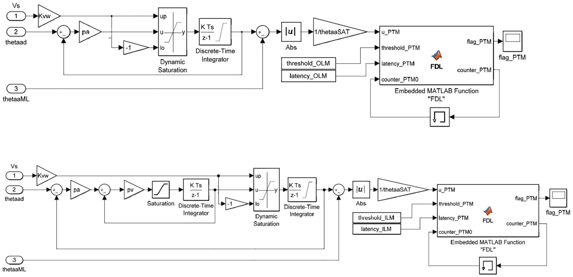
PTM MATLAB–Simulink implementation: outer loop monitor (up) and inner loop monitor (down).
Monitors’ parameter definition
The definition of the PTM’s parameters could appear an issue. Seven parameters are needed for the OLM (uth, latPTM, TM, θaSAT, Kvω, ωaSAT and pa) and nine for the ILM (the OLM ones, plus αaSAT and pv). Nevertheless, the identification of predictors’ parameters is not critical, because actuator performance limits (θaSAT, Kvω, ωaSAT and αaSAT) can be directly derived from system data, while dynamic response characteristics (pa and pv) can be estimated from control design results and/or experiments. In addition, the monitors’ sample rate TM is typically driven by the real-time execution requirement, and the fault counter threshold latPTM is essentially imposed by the maximum allowable fault detection latency (for the reference EMAS, ≤200 ms). For these reasons, the parameter tuning for both PTMs has been limited to the normalised error threshold uth only, by identifying the value for which no false alarms arise and any mechanical jamming fault is detected within 100 ms.
This activity led to the definition of PTM’s parameters given in Table 1.
Monitors’ parameters.

OLM: outer loop monitor; ILM: inner loop monitor.
The value is equivalent to a fault detection latency ranging from 80 to 160 ms.
Health monitoring algorithms’ performances
Testing method and failure mode definition
The two versions of the PTM have been compared in terms of fault detection capabilities using as ‘virtual’ hardware, a high-fidelity model of the EMAS,17,18 which includes the simulation of
The 3-phase brushless DC motor;
The power electronic drive with MOSFET switching logics;
The field-oriented motor control (Park transforms);
The DSP of the EMAS control and monitoring functions;
The sensors’ errors (i.e. bias, drift, noise);
The motor friction and gearbox mechanical losses;
The first vibrational mode of the EMAS mechanical assembly;
The hinge freeplay;
The aerodynamic loading;
The major system faults (e.g. mechanical jamming, motor faults, sensor faults).
Both the high-fidelity model and the PTMs have been stimulated by the command time history of a light military jet trainer elevator during severe pull-up/pull-down manoeuvres, 21 and the behaviour of the PTMs has been observed by injecting in the high-fidelity model the major electrical faults, such as open or shorted coils 23 and abrupt voltage decrease, as well as a temperature-induced degradation of the motor magnet properties 24 (a more ‘hidden’ fault that is difficult to be identified via sensors). The following five test cases have thus been obtained:
Normal operation, that is, no faults;
Failure mode 1 (FM1), that is, no faults for t < 10.4 s:
One open circuit fault for 10.4 s ≤t < 20.8 s; Two open circuit faults for t≥ 20.8 s;
Failure mode 2 (FM2), that is, no faults for t < 10.4 s:
One short circuit fault for 10.4 s ≤t < 20.8 s; Two short circuit faults for t≥ 20.8 s;
Failure mode 3 (FM3), that is, no faults for t < 10.4 s and a stepwise 40% performance degradation of the motor permanent magnet for t≥ 10.4 s;
Failure mode 4 (FM4), that is, no faults for t < 10.4 s and a stepwise 30% decrease of the voltage supply level (with respect to the normal operation) for t≥ 10.4 s.
The tests have also been used to verify the applicability of the PTM predictors in case of aerodynamic loading. Actually, both predictors are developed with reference to the actuator response at zero external load, so the accuracy is expected to lower during manoeuvres with fast and large-amplitude deflections (i.e. high dynamic loads), due to the actuator dynamic compliance. 25
Monitors’ performances
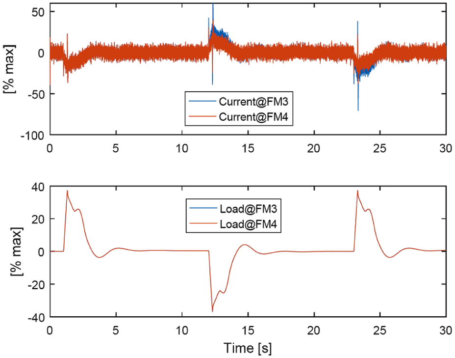
The simulation results, given in terms of normalised quantities for output position, motor speed, motor current and aerodynamic load, are presented in Figures 5–13. They demonstrate that the two versions of the PTM have similar performances in terms of false alarm rejection (Figure 7), motor coil fault detection (both are insensitive to the first fault, while the second one is promptly detected; Figure 10) and voltage decrease detection (Figure 13), while only the ILM is capable of detecting magnet degradation phenomena (Figure 13). In addition, both predictors demonstrate a low sensitivity to actuator loads. The results from Figures 5–7, related to a flight manoeuvre with no faults, point out that both algorithms are robust with respect to false alarms. Even when the EMAS is required to move with strong accelerations (e.g. at t = 1.3 s, where an abrupt speed change is commanded to the elevator), the maximal values of the fault counters are lower than 40% of the detection threshold for the OLM and 30% for the ILM. The results from Figures 8–10 are instead related to the operation with open and short circuits to the motor coils (FM1 and FM2), and they highlight that both algorithms are not capable of detecting the first electrical fault. Actually, the effects of the first coil fault on the EMAS position dynamics are minor (Figures 8 and 9), thanks to the PWM ‘phase-isolating’ drive design. On the other hand, both algorithms succeed in detecting the second coil fault, with a fault detection latency of about 1 s for the open circuits and 0.1 s for the short circuits (Table 2).

EMAS response in normal operation: actuator position and motor speed.

EMAS response in normal operation: motor current and aerodynamic load.
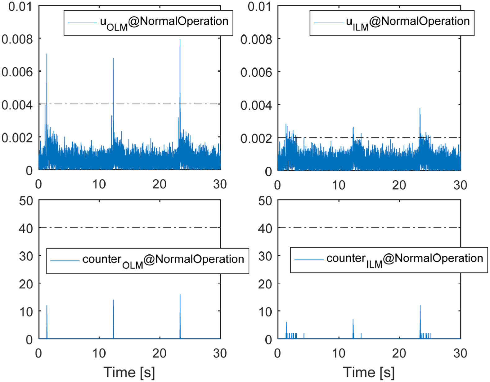
PTM residuals and fault-state counters in normal operation.
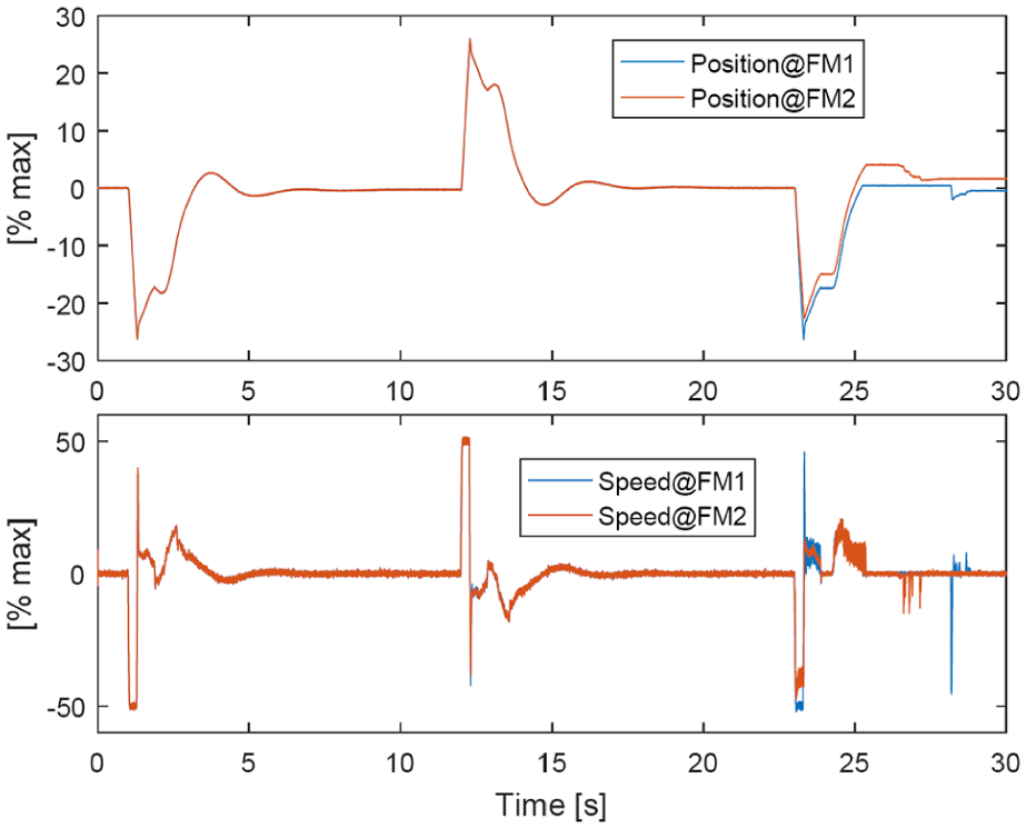
EMAS response in failure modes 1 and 2: actuator position and motor speed (1st fault at 10.4 s; 2nd fault at 20.8 s).

EMAS response in failure modes 1 and 2: motor current and aerodynamic load (1st fault at 10.4 s; 2nd fault at 20.8 s).

PTM residuals and fault-state counters in failure modes 1 and 2 (1st fault at 10.4 s; 2nd fault at 20.8 s).

EMAS response in failure modes 3 and 4: actuator position and motor speed (fault at 10.4 s).
EMAS response in failure modes 3 and 4: motor current and aerodynamic load (fault at 10.4 s).

PTM residuals and fault-state counters in failure modes 3 and 4 (fault at 10.4 s).
Monitors’ fault detection latencies (evaluated from the beginning of the manoeuvre next to the fault injection).
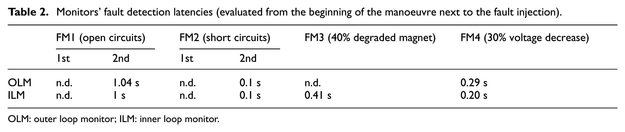
OLM: outer loop monitor; ILM: inner loop monitor.
Finally, the results referring to the operation with a motor magnet degradation and an abrupt voltage decrease (FM3 and FM4, from Figures 11–13) demonstrate that both algorithms exhibit a good behaviour for FM4, while only the ILM is capable of detecting magnet degradation phenomena (Figure 13 and Table 2).
Conclusion
Two health monitoring algorithms for electromechanical actuators, based on nonlinear time-discrete real-time executable position predictors have been developed and characterised in terms of fault detection capabilities. A high-fidelity model of an electromechanical actuator for flight controls has been used to evaluate the algorithms’ performances by simulating severe flight manoeuvres, in normal operation as well as with motor coil open and short circuits, motor magnet degradation and voltage supply decrease. The two algorithms have similar performances in terms of false alarm rejection, as well as in the detection of major electrical faults (coil faults and abrupt voltage decrease), but only the algorithm based on a more accurate speed predictor is capable of detecting motor magnet degradation, which is a more ‘hidden’ fault, difficult to be identified via sensors. This work provides indications about possible enhancements of EMAS health monitoring management logics, which could solely use a second-order PTM for prompt fault detection and fail-safe mode engagement, while additional actuator monitors could be dedicated to fault isolation only.
Footnotes
Handling Editor: Yong Chen
Declaration of conflicting interests
The author(s) declared no potential conflicts of interest with respect to the research, authorship and/or publication of this article.
Funding
The author(s) received no financial support for the research, authorship and/or publication of this article.