
Abstract
On account of radiant time factors method, this article presents a computed way of floor radiant cooling loads using radiant time factor procedure program to compute floor radiant time factors and to get floor radiant heat gains by test data collected within 24 h, then dynamic floor radiant cooling loads could be acquired by matrix operations. Five experimental conditions are selected to validate the calculated results. The experimental results indicate that the crest value errors between room-cooling loads and separating cooling loads about each condition are among the range −3.2% to 4.7%, and the mean value errors are less than 6.1%. The floor radiant cooling loads decrease and delay according to the changes of floor radiant heat gains. Crest value errors between measurement cooling loads and calculation cooling loads are among the range −1.8% to 2.3%, and the mean value errors are not more than 3.2%. Taking radiant time factor procedure program to compute corresponding building room floor radiant time factors with three types of building envelope, floor radiant cooling loads’ characteristics would be obtained under two conditions such as different radiant time factors and different radiant heat gains. So the room floor radiant time factors are calculated by radiant time factor procedure program, and building room floor radiant cooling loads can be computed.
Keywords
Introduction
Air conditioning cooling load is the foundation of cooling supply for building room air conditioning unit, and it is the key to evaluate energy-saving effect. 1 Because of high energy consumption in buildings, there is a great deal of interest in improving energy efficiency and increasing precision about cooling load computing methods.2,3 The radiant time factors (RTF) method4,5 is a new computed way of calculating room cooling loads in air conditioning system, which was described systematically by Spitler and recorded in ASHRAE handbook fundamentals. According to the new computed way, room-heat gains are split into convection heat portion and radiation heat portion. The convection heat portion could be immediately converted into indoor region cooling loads. As for the radiation heat portion, RTF method is used to compute building room indoor area radiant cooling loads, which means that the transfer function method can be replaced because of avoiding iterative calculation.6,7
The radiation heat portion is assimilated by the building structure envelope in room region, though it becomes cooling loads, and the radiant cooling loads can be computed by building palisade structure RTFs. There are two methods to count building palisade structure RTFs. 8 One method is that to generate RTFs using a calculation software that is based on the energy conservation equation.9,10 The other method is to obtain RTFs from existing ASHRAE transfer function database.11–13 The transfer function coefficients are extracted from the foundation of building structure envelope material’s thermal properties to compute RTFs through matrices calculation of transfer function coefficients. In both methods, the RTFs are for the entire building structure envelope, and the radiant cooling loads calculation result is also about the entire building structure envelope.14,15 Accordingly, building room floor radiant cooling loads can be computed by the room floor RTFs, which is named building room solar RTFs.
For radiation heat research by scaled experimental setup, Lirola et al. 16 presented a complete review on scale model testing for building, considering static and dynamic, acoustics, lighting, aerodynamics, and thermodynamics for energy efficiency. Cai 17 investigated the thermal comfort of a radiant heating/cooling (RHC) system in hot and humid climates by computational fluid dynamics (CFD) method. Gutierrez et al. 18 provided results of a small-scale displacement diffuser coupled with radiant floor cooling, and first reported the standing wave, named thermal jump experimental evidence. These research results estimated the result based on radiant floor combination with displacement ventilation and supplied reference for floor radiant cooling loads calculation.
In this article, the computed way of floor radiant cooling loads will be presented. It is set up on the basis of RTF method. According to floor radiant heat gains, to compute room floor radiant cooling loads through building room floor RTFs, which could be obtained through RTF procedure program. Then, the calculated values are compared with the measurement data to analyze the changing patterns between the inner surface heat flux and supply air flow rate. The study results present a new method to compute room floor radiant cooling loads on the basis of the room floor RTF way, and then load characteristics of building room floor radiant cooling loads on account of RTFs are studied. The results point out orientation about the computed way of radiant transfer loads in large space, which is transformed from radiant transfer heat between non-air conditioned region and air conditioned region.
Experimental principles and experimental system setup
Procedure for RTFs methods
The RTF way procedure transforms successive time radiant heat gains into hour by hour radiant cooling loads by building envelope RTFs. The radiant cooling loads at time τ is related to radiant heat gains at time τ and its past values of radiant heat gains. The building envelope radiant time series factors show the effects of radiant cooling loads at time τ that is accessed into the room every time. In this way, hourly radiant cooling loads can be computed according to hourly radiant heat gains, and that statement is as shown in equation (1)4,5

The radiant cooling loads could be easily obtained through the RTFs way. The 24 equations could be restructured, as shown in equation (2)
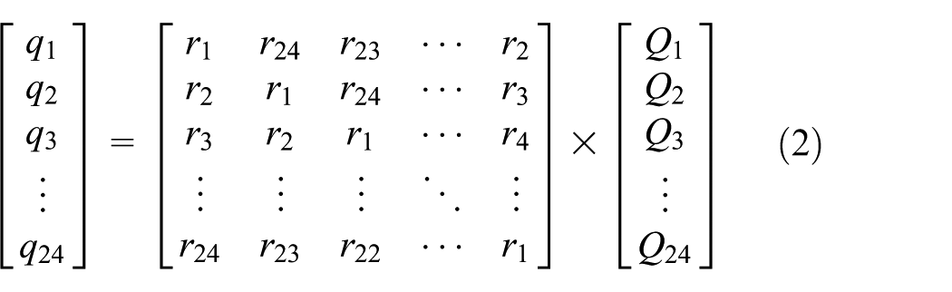
Equation (2) could be rewritten more briefly as

According to the structural features and thermal information of the laboratory envelope, set the parameters in RTF procedure program, and the chamber room floor RTFs could be computed as shown in Figure 1. RTFs hour by hour indicate clearly the percentage of radiant heat gains in τ hour, which was changed to room radiant cooling loads. We can make out the thermal storage capacity of room floor from the 24-term floor RTFs. The first item of experiment chamber room floor RTFs is 0.65. 19

Chamber floor radiant time factors.
Determination method of floor radiant cooling loads
According to energy balance of building inner surface, the energy equation coupled with heat conduction, radiation, and convection is proposed.20,21 With regard to surface i, energy conservation formula could be written as displayed in equation (4)

With inner surface emissivity, radiant angle coefficient, and inner surface temperature, the radiant heat gains QiR can be obtained by effective radiant method and the active net radiant heat. We can also calculate the inner surface net radiant heat using column matrix as in equations (5)–(6) 22


In experiment, to imitate chamber building surface thermal conduction through heat flux generated by the electro-thermal film, meanwhile the chamber net radiant heat takes place among high-temperature chamber surfaces furnished with generating heat flux electro-thermal film and other low-temperature chamber room surfaces. 8 To measure chamber room wall conduction thermal flux through thermal flux sensor; to calculate chamber room wall net radiant heat quantity by the equation (5)–(6); to obtain chamber room wall convection heat through energy balance equation as shown in equation (4). In experiment, the radiant heat gains are collected by chamber building walls net radiant heat. With the convection and radiation separating method, we can obtain the separating cooling loads by collecting the wall convection thermal quantity of chamber building wall surfaces23,24 and calculate the room-cooling loads through heat quantity interpolation among supply air and exhaust air. For the room, chamber floor radiant heat gains are building room floor net radiant thermal quantity, which can be calculated by effective radiation method; floor radiant cooling loads are building room floor calculation convection thermal quantity, which can be obtained easily through the convection and radiation separating method.
Experimental system and measurement plan
The laboratory is equipped with a chamber, air conditioning treatment unit, cold-water chiller, measurement and control system, and so on. Operating conditions were carried out in the chamber (in test experiment, length is 2.5 m, width is 2.1 m, and height is 2.5 m). Test chamber is positioned in an outside laboratory with a given stable air temperature, which is operated by a separated air conditioner. As presented in Figure 2, in experiment, to cool the return air through cooling coil and then to press it into the chamber we use a fan. Using quantity changer we can control the supply air flow. We can imitate chamber wall surface thermal conduction using heat electro-thermal films. Electro-thermal films were attached to the chamber surfaces to make them having identical emissivity. Eight thermal-measuring sensors were used to test chamber indoor air temperature (four strings, each string had two measuring sensors). For chamber inner surface, south surface with heat electro-films had four measuring sensors; two measuring sensors were arranged on the west, east, north surfaces and on the roof and the floor. Two measuring sensor were decorated to test supply air and exhaust air, respectively. For inner surface heat flux measurement, seven heat flux sensors were equipped to measure chamber wall thermal flux; south surface had two heat flux sensors, and the other wall had one heat flux sensor, respectively. 8

(a) System diagram of experimental rig and (b) testing points distribution sketch.
To imitate dynamic chamber surface heat flux, a cycle way was applied to the inner surface electro-thermal films. In experiment, the inner surface electro-thermal films were handled through cycle ways (to change electro-thermal films heat flux as sinusoidal) and electro-thermal films heating was operated as shown in equation (7). The air flow meter is used to test supply and return air flow rate. We use a temperature sensor to measure chamber indoor air temperature, supply and exhaust air temperature, and chamber room inner surface temperature and a thermal flux sensor to measure chamber inner surface heat flux. 16 The parameters of testing sensors are shown in Table 1. Five experimental conditions are selected to verify the calculation results. Table 2 shows the operating parameters under experimental conditions. Using a cycle way to operate chamber surface electro-thermal and making chamber room-cooling loads as cycle, the chamber air temperature is kept stable through supply air temperature changed cyclically. To eliminate the initial effects of building structure envelope thermal storage, a complete experiment was performed which lasted 42 h. The periodic analytical data were recorded during the last 24-h period, and the earlier 18 h was the elimination of thermal storage effects experimental stage

The parameters of testing sensors.

Experimental conditions operating parameters.
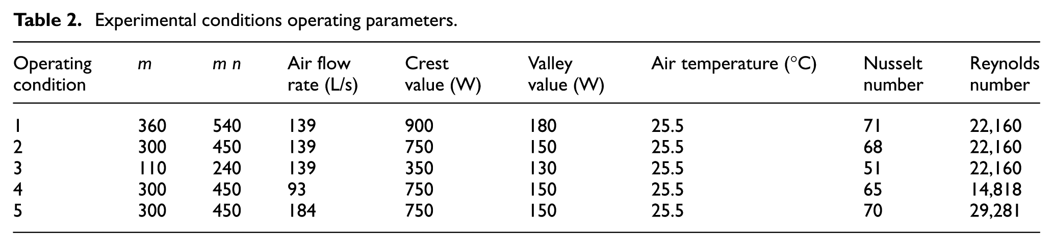
The Nusselt number (Nu) and Reynolds number (Re) can be expressed as


Experimental verification of floor radiant cooling loads
Separating cooling loads calculation
Radiant heat gains are assimilated by room structure envelope, then released into a region and become radiant cooling loads finally. In experiment, taking convection and radiation separating method, we can calculate surface convection and add whole room surfaces convection heat, namely, the separating cooling loads. We can calculate cooling loads easily by measuring supply air and exhaust air parameters, namely, room-cooling loads. For five conditions, Figure 3 shows the relationship among room-cooling loads and separating cooling loads. Figure 3 indicates that room-cooling loads and separating cooling loads varied periodically, the reason is that the south-wall inner surface heat flow changed periodically.

Verification of separating cooling loads: (a) condition 1, (b) condition 2, (c) condition 3, (d) condition 4, and (e) condition 5.
Five experimental conditions are selected for analysis, the difference between room-cooling loads and separating cooling loads is small. The crest value errors between room-cooling loads and separating cooling loads about each condition are among the range −3.2% to 4.7%, and the mean errors fall between 0.9% and 6.1%. As presented in Figure 4(a), the supply air flow volume remains the same (conditions 1, 2, and 3) and the chamber south-wall inner surface thermal flux increases. It can be seen that both the Nusselt number of the room-cooling loads and separating cooling loads increase. From Figure 4(b), when the south-wall inner surface heat flow maintains invariable (conditions 4, 2, and 5), the supply air flow volume increases gradually. It could be observed that the Nusselt number of the room-cooling loads and separating cooling loads increase slightly according to the increase in Reynolds number.

Nusselt number of room-cooling loads and separating cooling loads: (a) conditions 1, 2, and 3; (b) conditions 4, 2, and 5.
Floor radiant cooling loads calculation
Using RTF procedure program, we can obtain floor RTFs. With the hourly tested wall’s inner surface temperature, we can calculate floor radiant heat gains by effective radiant method through equations (5)–(6). The floor radiant heat gains are assimilated through chamber floor then released into chamber air and becomes floor radiant cooling loads finally. We can get the floor radiant cooling loads easily by the convection and radiation separating method, namely, floor measurement cooling loads. According to 24-term floor RTFs, hourly dynamic floor radiant cooling loads can be computed by equation (1), which is named floor RTF calculation cooling loads. Five experimental conditions are selected to validate calculation results. Figure 5 shows the comparison results about chamber floor radiant heat gains, floor measurement cooling loads, and floor calculation cooling loads. From Figure 5, it should be noted that, as time goes by, floor radiant heat gains and dynamic floor radiant cooling loads increase during the first half cycle and decrease during the second half cycle because of periodical thermal flow from heating the south-wall. Comparing with floor radiant heat gains, dynamic floor radiant cooling loads are slightly smaller during the first half cycle and slightly larger during the second half cycle. It indicates that floor radiant cooling loads decrease and decay comparing with floor radiant heat gains. The course generates a time delay and suppressing impact because of thermal storage peculiarity of room floor.

Radiant heat gains compared with radiant cooling loads: (a) condition 1, (b) condition 2, (c) condition 3, (d) condition 4, and (e) condition 5.
It should be noted that the crest value deviations are among the scope of −1.8% to 2.3% and mean value deviations are from 0.4% to 3.2% (in five conditions). Moreover, Figure 5 shows that the floor radiant cooling loads are slightly lagging when compared with floor radiant heat gains. The reason is that the heat storage properties of chamber are well. As depicted in Figure 6(a), since the south-wall inner surface thermal flux increases and supply air flow volume remains the same (conditions 1, 2, and 3), the crest value Nusselt number of measurement cooling loads and calculation cooling loads both increase, the mean value Nusselt number of them increase too. As shown in Figure 6(b), when the south-wall inner surface heat flow maintains invariable and the supply air flow volume increases gradually (conditions 4, 2, and5), the Reynolds number increase, the crest value, Nusselt number, and mean value Nusselt number of measurement cooling loads and calculation cooling loads increase slightly.

Nusselt number of floor cooling loads: (a) conditions 1, 2, and 3; (b) conditions 4, 2, and 5.
Characteristics analysis of floor radiant cooling loads
Building envelope and floor RTFs
Building structure envelope floor RTFs depend on building structure and thermal properties. Three typical building envelope forms are shown in Table 3. The building structure descriptions of exterior wall, interior wall, the roof, and the floor are from related documents (ASHRAE handbook fundamentals 2013). 5
The typical building structure descriptions.
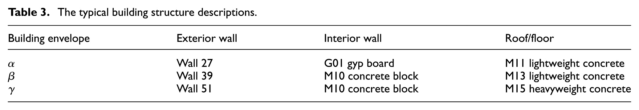
According to the three kinds of building structure descriptions in Table 3, and with RTF procedure program, RTFs are calculated. The layer material’s thermal properties of walls are set in RTF procedure program, considering outside surface resistance F01 and inside surface resistance E0; outside and inside surface resistances should be provided as the first and last layers, respectively. We can calculate RTFs by RTF procedure program 25 and compute floor radiant cooling loads through RTF (as shown in Figure 7). From Table 3 and Figure 7, the first item of building envelope α, β, γ RTFs are 0.54, 0.48, and 0.45, respectively, and the first value shows the transformation ratio among floor radiant heat gains compared with floor radiant cooling loads.

Floor radiant time factors: (a) building envelope α, (b) building envelope β, and (c) building envelope γ.
RTF indicates transformation ratio about radiant heat gains and radiant cooling loads in τ hours. The building heat stockpile’s ability of room enclosure structure could be gained through RTFs.
Floor radiant cooling loads calculation and analysis
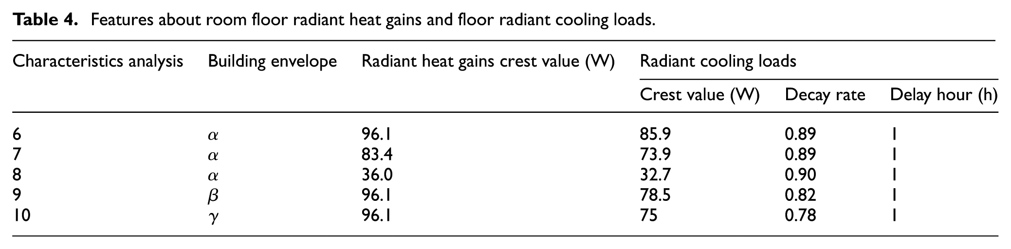
To analyze floor radiant cooling loads characteristics and calculate floor radiant cooling loads of two kinds of conditions we use different radiant heat gains and different floor RTFs. Figure 8 shows floor radiant heat gains compared with floor radiant cooling loads. Relative to radiant heat gains, the crest value of radiant cooling loads decayed and delayed.

Floor radiant heat gains compared with floor radiant cooling loads: (a) condition 6, (b) condition 7, (c) condition 8, (d) condition 9, and (e) condition 10.
As shown in Table 4 and Figure 9(a), the delay hours about crest value are alike. Since crest values of radiant heat gains increase (conditions 6, 7, and 8, the different radiant heat gains, the same building envelope type), decay rate, which is the ratio about radiant cooling loads compared with radiant heat gains, is constant at about 0.89, and the crest value Nusselt numbers of radiant cooling loads increase. As depicted in Table 4 and Figure 9(b), with different building envelope type (conditions 6, 9, and 10, the same radiant heat gains), the decay rates decrease and are among the range 0.90–0.78. The floor radiant cooling loads characteristics depend on building floor thermal properties.
Features about room floor radiant heat gains and floor radiant cooling loads.

Floor cooling loads characteristics: (a) conditions 6, 7, and 8; (b) conditions 6, 9, and 10.
Conclusion
Floor radiant cooling loads could be computed through the investigative RTF method. Five experiments were carried out and floor radiant cooling loads characteristics were obtained. Conclusions can be drawn as follows:
This study presents a computed way of radiant cooling loads upon account of the RTF method. Five experimental conditions are selected to validate calculation results. The results indicate floor radiant cooling loads decrease and delay on the basis of floor radiant heat gains, and the crest value errors are among the range of −1.8% to 2.3%, and the mean value errors are from 0.4% to 3.2%.
With convection and radiation separating method, the room-cooling loads and separating cooling loads can be computed, and the experiment results indicate that they agree well. The crest value errors between room-cooling loads and separating cooling loads with each operating condition are among the range of −3.2% to 4.7%, and the mean value errors are from 0.9% to 6.1%.
The floor radiant cooling loads characteristics depend on building floor thermal properties. The ratio of radiant cooling loads comparing with radiant heat gains, namely, decay rate, is constant at about 0.89 with the different radiant heat gains. The decay rate is among the range 0.90–0.78 with the different building envelope types.
Taking the RTF to calculate the radiant cooling loads, this method can avoid iterative calculation compared to transfer function method. At present, the RTFs all for entire building structure envelope, then radiant cooling loads calculation result is about entire building structure envelope. In this article, the room floor RTFs are calculated by RTF procedure program and building room floor radiant cooling loads can be computed.
Footnotes
Appendix
Handling Editor: Hyung Hee Cho
Declaration of conflicting interests
The author(s) declared no potential conflicts of interest with respect to the research, authorship, and/or publication of this article.
Funding
The author(s) disclosed receipt of the following financial support for the research, authorship, and/or publication of this article: This research was supported by the Zhejiang Provincial Natural Science Foundation of China under grant no. LY18E080022, the National Natural Science Foundation of China under grant no. 51278302, and the Jiaxing University Research Foundation under grant no. 70516003.