
Abstract
This article studies the causes of the time-varying stiffness of harmonic drive gear and the number of meshing teeth and the meshing length under different torques. Multi-pair tooth meshing characterizes the operating process of the harmonic gear reducer. However, the change of the number of meshing pairs is still not clear. Therefore, the mechanism of the time-varying stiffness of harmonic drive gear was studied using both the theoretical approach and simulation method, and the mathematical model of the time-varying stiffness of harmonic gear reducer was established. Moreover, a method for calculating the torque under different stiffness values was proposed. The relationship between varying torque and time-varying stiffness was established by the number of meshing teeth pairs. The established time-varying stiffness model and the proposed method are feasible, and the effectiveness was proved through experimental research. This study provides theoretical support for the analysis of load distribution in the flexible wheel by the stress–strain loads and related problems.
Introduction
Since the advantages of high transmission accuracy and compactness, harmonic gear has been widely used in high-precision equipment such as the robots. Research and experimental results showed their time-varying characteristics, which are mainly manifested in time-varying stiffness, hysteresis, and error.
Literature studied time-varying stiffness and hysteresis. For example, the time-varying stiffness of harmonic gear was experimentally verified in references.1–4 Through finite element analysis, Rheaume et al.5,6 studied the time-dependent torsional stiffness of a harmonic drive and proved there are time-varying characteristics in the transmission process of harmonic gear reducer. Some scholars further researched the characteristics of harmonic gear reducer on an experimental basis. Curt Preissner et al. 7 Through finite element analysis, Rheaume et al.5,6 proposed a parallel slip model to simulate the time-varying characteristics and experimentally verified the results. Taghirad and Belanger 8 analyzed the torque fluctuation and eccentricity using a torque sensor installed inside the harmonic drive gear. Using a similar approach, Jung et al. 9 analyzed the torque fluctuations, and through experimental research, he proved the torque fluctuation at the joint of the robot is obviously reduced. Roberts et al. 1 tested first the stiffness stability of a harmonic drive gear in thermal vacuum under different lubrication conditions, and the experimental results showed the stiffness does not significantly reduce. Ma et al. 10 detected and measured the effect of harmonic drive gear meshing zone on stiffness and friction hysteresis using the computer vision. According to existing literature, the stiffness of the time-varying phenomenon through experimentation or simulation has been proved; however, neither their sources nor the causes of time-varying stiffness in meshing process have been found.
For harmonic gear drive, the shape of wave generator in the unloaded state determines the deformation of the flexible gear. It becomes more complex in the loaded state because of not only the wave generator but also the loading torque, and the contact level of rigid gear and flexible gear contribute to the deformation. At present, scholars study the deformation of the flexible gear mainly by taking the centerline of the flexible gear as the research object. As the deformation of the flexible gear is extremely complex, the position of the maximum stress and strain cannot be accurately predicted. Kayabasi and Erzincanli 11 proposed a method for calculating the stress and strain of flexible gear tooth based on finite elements. Through theoretical and simulation approaches, Chen et al.12,13 proved that the centerline of the flexible gear does not extend and analyzed the tangential deformation of the flexible gear under both no-load and load conditions by the theory of finite element. Kosse 14 regarded the deformation of the centerline of flexible gear as a two-dimensional (2D) plane deformation and described it through radial and tangential displacements. However, Dong 15 and Dong and Wang 16 thought the deformation of the centerline should belong to three-dimensional (3D) deformation. Therefore, according to Kosse, 14 he added a degree of freedom to the model and analyzed the characteristics of the centerline of flexible gear under the no-load and load conditions. He found that the strain of the centerline of flexible gear changes linearly under the no-load condition. However, the change is non-linear under load. In the analysis of wave generator movement, Li et al. 17 found that under load, an angular difference exists between the neutral line and the longitudinal axis of the wave generator. Zou et al. 18 studied the stress and strain distribution of the centerline of flexible gear and analyzed the relationship between the distributions and the different loads. He found the deformation of the cross section of flexible gear changes with the increase in load torque, which was not included in the zone of load distribution at present studies. However, the distribution of displacement and stress increment remains unchanged. Therefore, the results of simulations and numerical calculations do not correctly represent the true deformation of the flexible gear because the deformation and the loading status of harmonic drive gearing vary with the torque, and the length of meshing line is also different under different torques. The literature mentioned above directly used the results of Ivanov. 19 The meshing zone of the flexible gear changes with the load after loading deformation. That is, the circumferential length of the meshing zone can be changed. For a particular type of harmonic drive gearing, the thickness of the flexible gear is defined. The length of the meshing zone can be known when the number of meshing teeth is known. Therefore, determining the length of the meshing zone under different torques is required first and then the research or demonstration for the load distribution of the flexible gear can be done. Simultaneously, since the number of meshing teeth also affects the rigidity of the gear system and the amplitude of the error component, it is meaningful to investigate the number of teeth in the meshing zone.
Establishment of torsional stiffness’ weak link and equivalent mathematical model
Harmonic gear driver is mainly composed of rigid gear, flexible gear, and wave generator. The wave generator forces the flexible gear to deform oval and rotates the flexible gear with the rigid gear under the effect of input torque. In the transmission process, because each part always is torsionally deformed, the total torsional stiffness of harmonic gear reducer can be obtained by the flexibility relationship of each part
where λH, λf and λn are flexibility of wave generator, cylinder of flexible gear, and meshing zone, respectively.
The torsional stiffness of wave generator corresponds to its radial stiffness, and it little affects system’s flexibility.
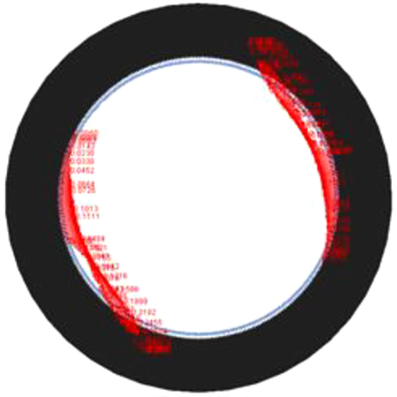
The flexible gear is a thin-walled cup structure, which is uneasy to calculate its torsional stiffness using mathematical methods. Here, the ANSYS software was used to solve the deformation of the flexible gear, and the solution was shown in Figure 1. The torsional stiffness of the flexible gear after conclusion is 391,025.95 N m/rad, which shows that the torsional stiffness of the flexible gear itself is also relatively large, which has little effect on the overall flexibility of the system.

The displacement diagram of flexible gear in ANSYS.
Therefore, one can assume that the stiffness of the meshing zone gives the overall torsional stiffness K of the harmonic drive

where Kn is meshing stiffness between the flexible gear and the rigid gear.
Both the research and experimental results show that the torsional stiffness of harmonic gear reducer changes with the load torque. The torsional stiffness increases when the load torque increases with a non-linear relationship. Tuttle 20 reported that the number of meshing teeth pair of a harmonic drive gearing is 25%–35% of the total number of teeth, under ideal operating condition. The degree of meshing of most of the meshing teeth pair is not the same under load; some teeth are in full meshing state, while others are in the non-fully meshing state. As Figure 2 shows, most of the meshing teeth pairs are in a non-fully meshing state, especially under small torque.
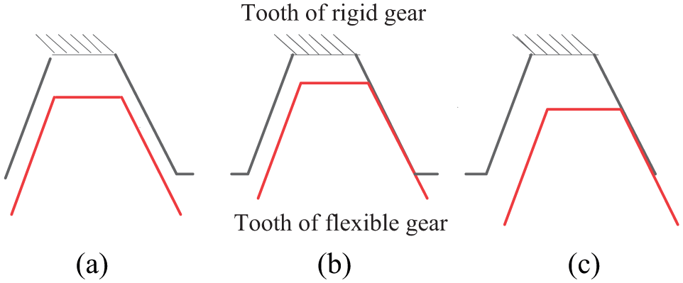
Meshing state of different teeth pairs: (a) unengaged state, (b) fully engaged state, and (c) non-fully engaged state.
In order to research the multi-tooth meshing of the harmonic drive gear caused by the deformation of flexible teeth, the harmonic drive XB1-80-type is taken as an example, and the deformation of flexible teeth and stiffness of the single tooth are analyzed. The basic parameters of the flexible gear were shown in Table 1. In the simulation analysis, the meshing force is assumed in the circumferential direction and regardless of its normal component. The tangential displacement of three different loading positions is calculated (see Figure 3). Position 3 is on a pitch circle, Position 1 is on tooth tip, and Position 2 is intermediate between the two. Here, the different loading positions correspond to different degrees of meshing; Position 1 is just the meshing state, Position 3 is fully meshing, and Position 2 is the semi-meshing state.
Basic parameters of the flexible gear.


Different positions of the force on the flexible gear tooth.
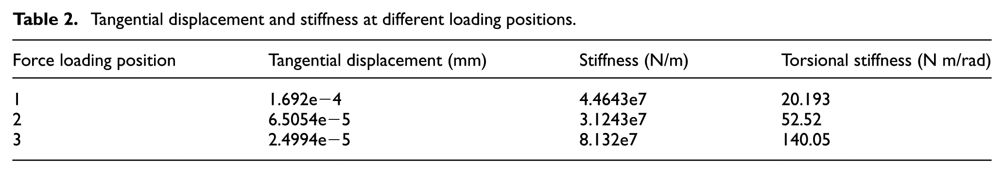
To solve the torsional stiffness of the flexible gear, it is necessary to extract the true tangential displacement. The tangential displacement is mainly obtained by the tangential displacement of the nodes near the loading point. In the finite element software ANSYS, add load to flexible gear tooth, displacement deformation can be obtained. The finite element model of flexible gear tooth was shown in Figure 4. The tangential true deformation displacement of flexible gear is the difference between tangential loading and unloading. Therefore, the displacement of tangential loading and unloading needs to be obtained to calculate the difference. Finally, the actual deformation displacement at each loading position can be got. Moreover, the line stiffness in the tangential direction can be calculated according to the relationship between tangential displacement and loading force. The torsional stiffness can be calculated according to the relationship between torsional stiffness and line stiffness. Table 2 shows the torsional stiffness calculated at different meshing states.
Tangential displacement and stiffness at different loading positions.

Finite element model of flexible gear.
From Table 2, different deformations correspond to different loading positions. At Position 1, tangential deformation is the highest and the torsional stiffness is lowest, whereas at Position 3, tangential deformation is minimum and torsional stiffness is highest. Under such condition, most of the teeth of flexible gear mate due to local deformation.
The output torsional stiffness of the system can be considered to be zero when teeth do not mesh together. In pace with the rotation of wave generator and overcoming the system friction and backlash, the number of teeth pairs is gradually increased. The meshing between the teeth of rigid gear and flexible gear can be seen as multiple spring compression process. The stiffness of each spring determines the meshing stiffness between teeth. Figure 5 shows the schematic of the equivalent stiffness of the meshing zone.

Schematic of equivalent stiffness of the meshing zone.
The gearing output torsional stiffness K was got according to the geometric relationship between the stiffness of wire spring and torsion spring

where Ki is meshing stiffness (N/m) of ith meshing tooth, i = 1, 2, 3, …, n, and ri is meshing radius (m) of the ith meshing tooth.
When the load of the harmonic gear drive changes, tooth deformation leads to a change in the number of teeth pairs in the meshing zone, and the output torsional stiffness also changes. According to the above description, the effective number of teeth pairs in the meshing zone mainly determines the torsional rigidity of the harmonic gear drive. Here considered, loading Position 3 corresponds to effective meshing teeth pairs, and the multi-meshing teeth pairs in other states could be regarded as equivalent to the loading Position 3 according to the relationship of springs connected in parallel. Namely, the meshing position between the rigid gear and the flexible gear is considered to correspond to Position 3. Combined with equation (3), the relationship between the number of effective meshing teeth pairs and the torsional stiffness of the harmonic gear drive is as follows

where Ks is equivalent torsional stiffness of single flexible teeth, and n(T) is a function of the load torque representing the effective number of teeth pairs when the torque is T.
The simulation above was carried out to verify the change process and to prove the number of meshing teeth in the meshing zone varies when the load torque changes.
Simulation analysis to verify the mathematical model
ADAMS is used to simulate the intermeshing process between the flexible gear and the rigid gear. The flexible gear itself is a flexible body. To make the simulation more realistic, the flexible gear part needs to be flexed in ANSYS. When flexible, the inner wall of the flexible gear was set as a rigid region, and the center position of the flexible gear was selected as a rigid point. The data were exchanged through the interface between ANSYS and ADAMS. The flexible body was replaced to ADAMS.
A rigid-flexible coupling model of harmonic drive gearing was established using ANSYS and ADAMS commercial software (Figure 6). Rigid gear is assumed to be rigid, while the flexible gear is flexible; the ring gear of flexible gear is modeled oval-shaped.

Rigid-flexible coupling model in ADAMS.
In ADAMS, the inner wall of the flexible gear was fixed, and drive torque was added to the rigid gear. The STEP function was used to simulate the role of the load resistance torque, and the simulation time was set to 10 s, the number of simulation steps was set to 5000. Figure 7 shows a diagram of force after the collision between the rigid gear and flexible gear under load of 0.5 N m. The red arrow means the meshing force between the meshing teeth between the rigid gear and flexible gear. It is clear that there are two distinct regions of the force contact area between the rigid gear and flexible gear. After further magnification, these two regions are the major axes after the deformation of the flexible gear.
Contact force diagram.
Then, meshing force of the single meshing region was obtained (Figure 8).
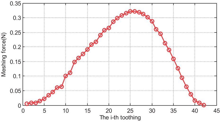
Curve of meshing force against meshing tooth.
There are about 42 teeth pairs to mesh in this torque. However, the meshing force is changeful. That is, the extent of meshing is not the same, and at least 60% of the maximum value of the initial meshing force is effective meshing, and at this point, there are 18 teeth pairs fully meshed. In order to study the variation law of the number of teeth pairs in fully meshing under different torques, different torques have been added to the simulation model. The number of effective meshing teeth pairs obtained by the simulation is shown in Figure 9.

The number of meshing teeth pairs versus load torque.
For small values of resistance torque, the number of teeth increases sharply with the increasing resistance torque. The number of effective meshing teeth pair increases rapidly when the load resistance torque is smaller than 10 Nm, and it is up to 37 at 10 Nm; for large values of torque, the number of teeth increases not obviously after torque increases. Therefore, the number of effective meshing teeth pairs increases slowly when the load resistance torque is bigger than 10 Nm. These results prove the number of meshing teeth varies with the load torque.
Figure 10 shows the results of the simulation carried out to investigate the relationship between the torsional stiffness of the system and the effective number of teeth under the effect of different torques. The linear relationship proves that the established mathematical model of the stiffness presented above is correct.

Relationship between the number of effective meshing teeth pairs and stiffness.
Therefore, for a certain type of harmonic drive gearing, the effective number of teeth pairs in the meshing zone is determined when the torque of the load is determined; moreover, because the meshing teeth of the meshing zone provide the torsional rigidity, the output stiffness is determined. At the same time, the tooth thickness of flexible gear teeth of the harmonic gear is known, and the length of the meshing line of meshing zone of the torque can be determined. The length of meshing line and wrap angle corresponding to meshing line are of great significance for stress–strain analysis and the analysis of load distribution of the loaded flexible gear. Then, an experiment to prove the feasibility and effectiveness of the method is carried out.
Experimental analysis of torsional stiffness of harmonic drive gearing
Torsional stiffness of harmonic drive gearing
This article designed an experimental setup to test the torsional stiffness of harmonic drives gearing. The setup (Figure 11) is mainly composed of stepping motor, torque sensor, XB1-80-type harmonic drive gearing, and the fixtures of the output part. The test system has a simple structure, easy operation, and versatility, and it is suitable for carrying out torsional stiffness measurement of various types of harmonic drives.

The experimental setup.
The experiment was established under the following assumptions: (1) constant transmission ratio was taken as the gear ratio during the tests, and it is independent of transmission ratio fluctuation; (2) the applied torque does not lose the output shaft; and (3) harmonic gear drive does not slip during the experiment, and regardless of the slipping of the flexible bearing and the inner wall of the flexible gear.
During the experiment, the output torque was measured with a torque sensor. A stepper motor measured the angular displacement of the input shaft, and the angular displacement of the output was calculated according to the transmission ratio. However, the angular displacement of the output shaft of the experimental device is determined by the harmonics of the gearing and the torque sensor; the angular displacement of the torque sensor needs to be subtracted from the relationship of flexibility when calculating the output shaft angular displacement.
N is the number of pulses entered by the stepper motor in real time, T is the torque value of torque sensor, and Ks is the torsional stiffness of torque sensor, thus the actual torque angle of the output shaft θo that can be written as

where
The experiments were carried out by running the motor in forward and reverse to obtain four different operating conditions, that is, forward loading, forward unloading, reverse loading, and reverse unloading. The number of input pulses and the output torque were recorded, and each experiment was repeated five times. The experimental data were filtered and processed after the experiment. Butterworth low-pass filter was added to data processing software to remove high-frequency interference components in the signal. The angular displacement of the torque sensor itself was subtracted, and the true torsional stiffness curve of the harmonic gear drive (Figure 12) is obtained.

Output torque versus twist angle curve.
The curve can be divided into two parts. In the first part, the angle of rotation goes from −80° to 80° (the horizontal line) indicating that the torsional stiffness of the segment is about zero because of backlash, which led to torque keep constant when the angular displacement of the flexible gear begins increasing. The other part is the smooth continuous increase or decrease in the curve, indicating the torsional stiffness of the harmonic gear reducer is changing. Besides, harmonic gear driver highlights a “hysteresis phenomenon,” as the two curves under forward loading and unloading are obviously not coincident. Reverse loading and reverse unloading were the same theory with forward loading and forward unloading, so it was not introduced again. In the following discussion, taking forward loading as an example, reverse loading was no longer excessively described. By fitting the curve related to forward loading experiment, the following formula is obtained

where θ is angle of rotation.
The interpolating points of fitting function compared to original data are shown in Figure 13.

The data fitting curve.
The data curve obtained by fitting equation (6) is an ideal curve. Since the slope of the curve is the torsional stiffness, the above-mentioned fitting curve is derived to obtain the torsional stiffness curve of the harmonic gear reducer. Moreover, the results of the simulation using the stiffness model are also transformed into stiffness as shown in Figure 14.

Torsional stiffness curve.
The torsional stiffness of the harmonic drive is small at small torque, as the order of magnitude of stiffness is 103 when the torque is smaller than 5 Nm, and it is not expected that the output stiffness of the harmonic drive is large due to multi-tooth meshing. When torque reaches 18 Nm, torsional rigidity is about 1.5 × 10⁴ N m/rad. Besides, the curve is same as that of simulated stiffness curve obtained in the previous simulation. However, the curves are not coincident mainly because ADAMS simulation did not consider the internal friction of harmonic drive and other factors. Thus, the true operating condition of the gear is not fully simulated when adopting flexible gear elliptical model. This leads the experimental and simulation results to deviate. However, as a result of large torque, the friction and other factors become less important, and the two curves are same. In the following section, the relationship between the number of meshing teeth pairs and the length of meshing line under different torques is investigated.
Relationship between torque and number of meshing teeth pairs and length of meshing zone
According to Figure 14, the effective number of teeth under different torques is shown in Figure 15. From the figure, the effective number of teeth pairs is the same as the simulated one, which showed that with the increase in the torque, the number of effective meshing teeth gradually increased. However, the rate of the number of teeth growth lowers and finally reaches the maximum number possible.

Effective number of teeth pairs in the meshing zone varying the torque.
When the number of teeth pairs varying the torque is obtained, the length of meshing line of the meshing zone can be obtained according to the ratio of the number of meshing teeth pairs to the total number of flexible teeth. For example, the number of effective meshing teeth pairs of single meshing zone is 35 and 50 when torque is 10 and 30 Nm, respectively. At this moment, the wrap length of single meshing zone is f10 Nm = 0.4375π and f30Nm= 0.625π, respectively. Therefore, the study of the deformation of flexible gear centerline under load first requires calculating the length of meshing line. Then, to investigate the deformation and load distribution of the centerline of flexible gear under the condition of loaded flexible gear load is of significance.
Conclusion
The main conclusions in this article are the following:
The equivalent stiffness model of meshing in the meshing zone was established, and the torsional stiffness of harmonic drive gearing was analyzed.
The variation of the number of meshing teeth pairs under different torque values was simulated. The results showed that with the increase in the torque, the effective number of teeth pairs is gradually increased, and the correctness of the time-varying model established in this article is proved.
Concerning the deformation of the flexible gear in the meshing zone due to loading, the number of meshing teeth pairs and the length of meshing lines under different torques were researched; these parameters were experimentally determined for a XB1-80-type harmonic driver.
This research reveals the mechanism of the time-varying stiffness of harmonic drive gearing and provides a theoretical basis for the further study of stress and strain and load distribution in the loaded zone of flexible gear.
Footnotes
Handling Editor: Shun-Peng Zhu
Declaration of conflicting interests
The author(s) declared no potential conflicts of interest with respect to the research, authorship, and/or publication of this article.
Funding
The author(s) disclosed receipt of the following financial support for the research, authorship, and/or publication of this article: This work was supported by the National Natural Science Foundation of China (51575007) and the Municipal Education Commission project of Beijing (JC001011201601).