
Abstract
Surface electromyography is commonly used as control signals for wearable devices. Compared to physical sensors, bioelectric signal are more sensitive to pressure and placement of interface. Discussion of these factors includes not only ergonomic issues but also control issues. Variations of the two factors in setup could lead to variability in output values. In this article, we mainly discussed the influence of the two factors, including contact pressure and placement, to estimate the elbow joint angles based on surface electromyography. To our knowledge, there has been no research about this problem. We first measured the surface electromyography signal with elbow flexion and extension motion, then estimated the angles of motion through the pattern recognition method, and finally assessed the distribution of contact pressure and the accuracy of regression. Our results indicated that the accuracy of angle recognition depends on the consistency of pressure distribution over the contact surface. The contact surface can be placed in the anterior of the upper arm at lower contact pressures. When high contact pressure is required, the placement of the strap should cover the muscle belly. The main contribution of this study is that our results can be used to guide the human–machine interface design of wearable devices.
Introduction
Surface electromyography (sEMG) is commonly used as control signals for wearable devices. Bioelectrical signals provide rich information from which a user’s intention in the form of a muscular contraction can be detected using surface electrodes. The joint angles are usually employed to identify the intentions of human movement, followed by motion planning and device control. Pulliam et al. 1 performed a feasibility study that demonstrated that an appropriately designed artificial neural network was capable of predicting continuous and simultaneous elbow and forearm joint angles. Tang et al. 2 further proved that the joint angles have been estimated based on sEMG signals by applying the proportional myoelectric control method. Koo and Mak 3 predicted elbow joint angles using electromyography (EMG) signals and reported large errors ranging from 9.5° ± 3.5° to 24.64° ± 7.79°. There are many reasons for increased errors, such as pattern recognition methods, load weight, and human–device interaction. In most studies, people pay more attention to optimize control methods for wearable devices. The ideal human–device interaction factors of the devices have not met yet. Sometimes, many factors are not only ergonomic issues but also control issues. Excellent interactive interface as well as ease of use must be ensured even before implementing the device’s control. For the device to be used, these are neither subjective inherent comfort element, the device must not limit the range of motion, nor burden the user while wearing the device. For the device to be controlled, human–device interfaces must minimize the impact on input signal in motion. Human body must be in contact with the wearable device flexibly, because the limb motion will lead to changes in joint axis position and muscle geometry. Since fixation of a device on a human limb is never rigid, slippage between the device and the limb will occur. This will lead to further misalignment between the mechanism and human joints. 4 In addition, contact positions must be considered in designing a wearable device. To our knowledge, there were no definitive statements. In many studies, the placement of the contact surface was different. For example, the contact position was placed near the elbow or placed on the upper edge of biceps brachii (BB).5,6
As systems require a close physical human–device interfaces, it is critical that contact pressure imposed on people by the device are maintained within safe ranges that ensure the health of the skin tissue. 7 Discomfort in cutaneous tissue may also be provoked by friction and forces caused by interactive interfaces. 8 Large contact pressure can lead to poor blood circulation, and small pressure will slide between the arm and the device in motion. In the past, researchers have studied the effects of temperature and humidity on human–device interfaces, specifically in exoskeleton and prostheses, in an attempt to characterize comfort during use. 9 As with the effects of other factors, it is essential to ensure the appropriate force exerted by the strapping interface during physical interactions between the wearable devices and to ensure normal operation of the device. However, the effect of varying the strapping condition of the subject is not known.
Compared to physical sensors, bioelectric signal are more sensitive to pressure and placement of the interface. Variations of two factors in setup could lead to variability in output values. In the article, we mainly discussed the influence of two factors, including contact pressure and placement, to estimate the elbow joint angles based on sEMG. So far, no scholars have done the discussion. We first measured the sEMG signal with elbow flexion and extension motion, then estimated the angle of motion through the pattern recognition method, and finally assessed the distribution of contact pressure and the accuracy of regression. Our results indicated that the accuracy of angle recognition depends on the consistency of pressure distribution over the contact surface. The contact surface can be placed in the anterior of the upper arm under lower contact pressures. When high contact pressure is required, the placement of the strap should cover the muscle belly. The main contribution of this study is that our results can be used to guide the human–machine interface design of wearable devices. We want to optimize these factors that can smoothly interact with human limb motion.
Method
Experiment protocol
In many studies, the interactive interface commonly used from wearable device to arm are straps or arm shells.10,11 The straps are used more commonly because arm shells usually need to be designed according to the individual. In our research, the strap was chosen as the contact interface, and material was nylon. The width of the strap was 50 mm consistently to ensure a better fit with the contact surface. Iida et al. 12 reported that moderate external pressure (50–100 mmHg for upper arm) does not produce complete occlusion of arterial inflow, but arterial blood flow was decreased with increasing levels of external compression. And, the specialized literature sets metrics regarding pressure on the human body at 30–35 mmHg for adequate circulation allowance before tissue oxygenation is impaired. 13 The pressure factors in our study were preset to two variables, respectively, 30 and 70 mmHg. The initial pressure values are measured by Force & Load sensors (B201, FlexiForce, Tekscan Inc., USA). The elbow joint connects upper arm and forearm. Usually, the contact placement of the forearm is fixed. Because there are smaller and more muscles in forearm, so the contact surface of the wearable device must be placed on the wrist. Pons 14 thought that wrist is a good place to fix the strap and limit discomfort. In addition, the impact of elbow rotation is mainly biceps and triceps in the upper arm. So, we only considered the contact position of upper arm. As shown in Figure 1, the placement of the contact was set to three factors, including the anterior of upper arm (placed near the elbow, under the BB), the posterior of upper arm (close to the shoulder joint, on the upper edge of BB), and the middle of upper arm (avoid covering the electrodes).

Experimental equipment and the placement of the contact surface and electrodes: (a) the self-made wearable device, (b) the posterior of upper arm, (c) the middle of upper arm, and (d) the anterior of upper arm.
Eight (six male and two female) healthy adult subjects without any previous history of elbow injury volunteered for this study. The mean (±standard deviation) age, height, and mass of the subjects were, respectively, 25.3 (±4.3) years, 168.2 (±8.5) cm, and 66.2 (±11.4) kg. All subjects were right-hand dominant and have good health during the experiment. Within 24 h before the experiment, the subjects did not carry out any vigorous exercise. All subjects had previously participated in similar motor control studies. Prior to beginning the experimental session, subjects received a written description of the project and signed informed consent forms. Subjects were then asked to perform a series of familiarization trials. This study was conducted according to the Helsinki Declaration (1964).
As shown in Table 1, there were seven trials in study, including six trials of two factors, and one trial of natural condition. The natural condition was the motion of elbow joint without wearing any device. In each trial, the subjects were asked to move the elbow from 0° to 90° and then back to 0°. The motion time for a trial was 5 s. Each subject completed five repeatability tests. Subjects were tested in sitting position and put on a self-made exoskeleton of upper limb. The weight of the device is 2 kg. The wearable device did not add any extra power, only moved with the elbow joint. Each subject performed elbow flexion and extension according to the verbal instructions of experimenter and kept the same speed as far as possible. The initial position of the forearm was perpendicular to ground. A minimum of 1 min of rest and relax the strap were allowed between each motion to mitigate the accumulation of fatigue.
Protocol information.

sEMG was collected from four muscles of the right upper limb: brachioradialis (BR), anconeus (AN), BB, and triceps brachii (TB). Human elbow is mainly actuated by these muscles. Through a large number of preliminary experiments and previous studies, we identify four arm muscles as suitable candidates for the designed recognition problem of elbow angles. By adjusting the amount of force generated by these muscles, the elbow angle can be arbitrary controlled. 15
Data acquisition and preprocessing
The sensors (MyoScan sensor), which connected with electrodes, could record the sEMG signals up to 1600 µV and an active range from 20 to 500 Hz. The sEMG signals during experiments were collected, amplified, and transmitted by a 10-channel digital sEMG system (FlexComp Infiniti System, Thought Technology Ltd, Canada). An electrogoniometer (RV30YN30S, TOCOS®, Japan) for measuring the elbow rotate joint angles. It has a voltage range of ±2 V which corresponds to a complete 360° range of motion. All data were collected at 1024 Hz. The raw sEMG signals and the elbow angles measurements are transferred to a personal computer through a serial interface (USB) by setting the system to offline mode. The sEMG signals were treated offline in MATLAB (The MathWorks, Version 8.3.0.532, 64-bit, 2014). The front-end processing is a preprocessing step to segment the input data. The segment length should also be sufficiently small to satisfy the myoelectric control application. 16 The myoelectric control must supply the control commands in less than 300 ms; thus, the sEMG signals were partitioned into 250 ms windows in this work. We use a high-pass filter with a cut-off frequency of 1 Hz to remove the bias and rectify the signal. A low-pass filter is used to remove the highest frequencies. Pressure measurement system was placed under the strap to acquire interface pressure distribution. A thin flexible resistive based sensor pad (Body Pressure Measurement System (BPMS), Tekscan Inc., USA) was used to capture pressure distribution at the interface. And, the captured data were converted to three-dimensional (3D) pressure distribution map by the Research software (Tekscan Inc., USA), which is an instantaneous distribution of pressure in the matrix of sensing elements.
Feature extraction and regression
Multiple features set have been employed and succeeded in the classification of motion-based sEMG signal in many researches. Therefore, in this work, because it has been widely used in recent research and has been simplified in the calculation process, features are extracted in the time domain and frequency domain.
Root mean square (RMS) is a relatively common sEMG signal time-domain feature, to a certain extent, reflects the contribution of each muscle group in the process of motion. RMS is the average of the square of the sEMG signal.
For sEMG signals, integral electromyography (IEMG) is a traditional way to detect the level of muscle contraction, and it is often used to in the study of signal feature extraction
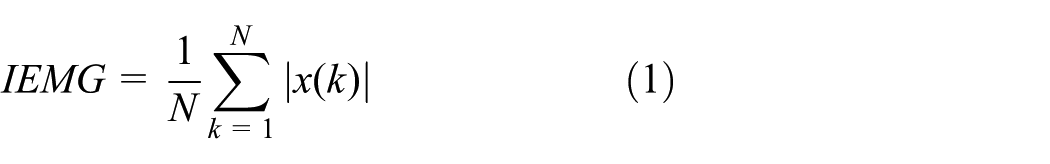
During dynamic contractions, median frequency (MDF) and mean frequency (MNF) of sEMG signal are the important process parameters, which reflect the complex physiological phenomena inside the muscle. MNF is defined as a sum of the product of sEMG power spectrum and frequency divided by a total sum of power spectrum. MDF is a frequency at which the sEMG power spectrum is divided into two regions with an equal integrated power. They can be expressed as 17


where Pk is the sEMG power spectrum at a frequency bin k, fk is the frequency of the spectrum at a frequency bin k, and M is the total number of frequency bins. In order to eliminate the effects of individual factors, each feature (RMS, IEMG, MDF, and MNF) was normalized with reference to the maximum muscle contraction measurement, with values between 0 and 1.
The support vector machine (SVM) theory introduced by Oskoei and Hu 18 exhibits good performance in classification and regression problems, separating data that cannot be separated linearly. The SVM maps data onto a high-dimensional space using a kernel function. In this study, Gauss radial basis function was applied to build recognition models. The mapped data are then expected to be easily classifiable by a hyperplane in the high-dimensional space. In the training phase, the training dataset was cross-validated to select the parameter and build the motion pattern recognition model. The target was the motion angle of the elbow.
Quantitative evaluation
The quality of regression was assessed using the root mean squared error (RMSE). It represents the predictive value of discrete degree, also called the standard error. 2 The best fitting is RMSE = 0. The averaged classification error for each subject was assessed offline by fourfold cross-validation of the training dataset.
Analysis of variance (ANOVA) was used to assess the significance of differences in the sEMG responses of the six motions. Two-factor ANOVA for repeated measures was used to investigate the performance of contact pressure and placement. Pressure and placement were independent variables with two levels and three levels, respectively, and RMSE was the dependent variable. The paired student’s t-test was used to further examine main effects between variables in each motion. Significance was accepted at p < 0.05.
Results
As shown in Figure 2, there are some deviations between the predicted and actual curves in all trials. The mean RMSE of the seven trials ranging from 8 to 17, with the lowest mean value in natural condition (8.9035), followed in A-L trial (10.9221) and the highest in P-H trial (16.7384). In the A-L trial, the regression curves of eight subjects showed a consistent characteristic, that is, high swing occurred at the begin and the end of the motion. The regression was better in the middle of the motion. This result was consistent with the trial of natural motion condition and demonstrated that the strap did not have a significant impact on motion performance. In addition, the regression of the M-H trial was relatively well, but there was a small amount of abnormal data during some motion. This showed that the recognition accuracy of motion angle is more prone to change at larger contact pressures.
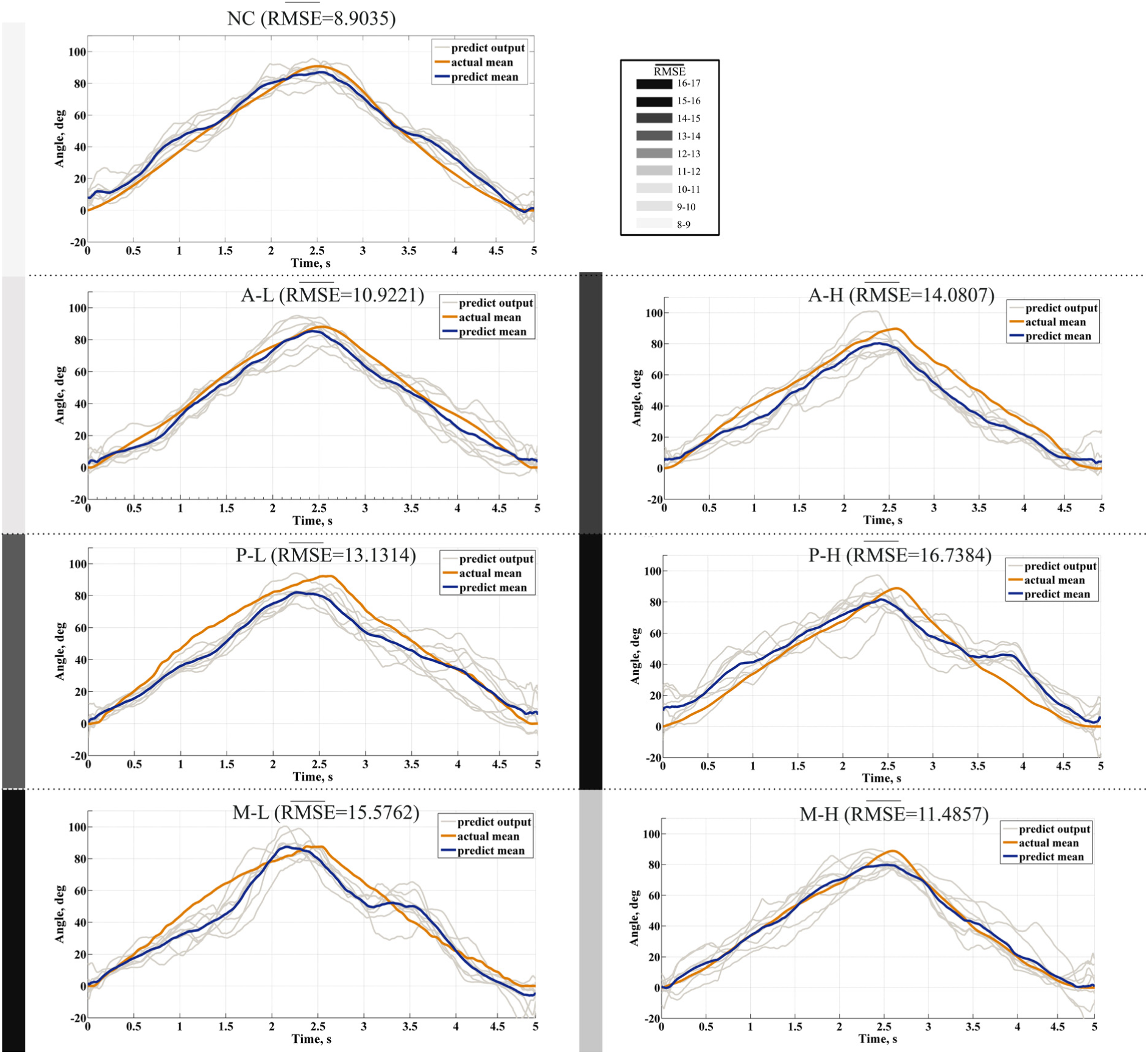
The curve of the actual angle and the predict angle using SVM.
As shown in Table 2, two-way ANOVA showed that the RMSE was affected by both pressure and placement significantly, and there were noticeable interactions between the two factors. Compared the two factors, the influence of placement on the accuracy of recognition was more significant (p < 0.01). The paired t-test was then used to analyze the two trials with low RMSE values. The results of the A-L and M-H trials showed no significant difference (p > 0.05). This might indicate that the strapping mode in both trials can be better used to the interaction interface of device.
Two-factor analysis of variance.
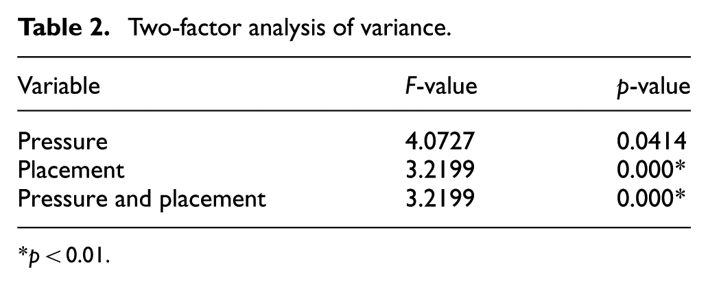
p < 0.01.
Figure 3 showed the box plot of RMSE values for six trials. It can be seen from the figure that the data of A-L trial had the best consistency and stability. Although the data of P-L trial also had high robustness, but the skewness was greater than the A-L trial. So, a large probability of abnormal data would be generated. When the strap was tied in the middle of the upper arm, there was an opposite result to the other two positions with the pressure increased.
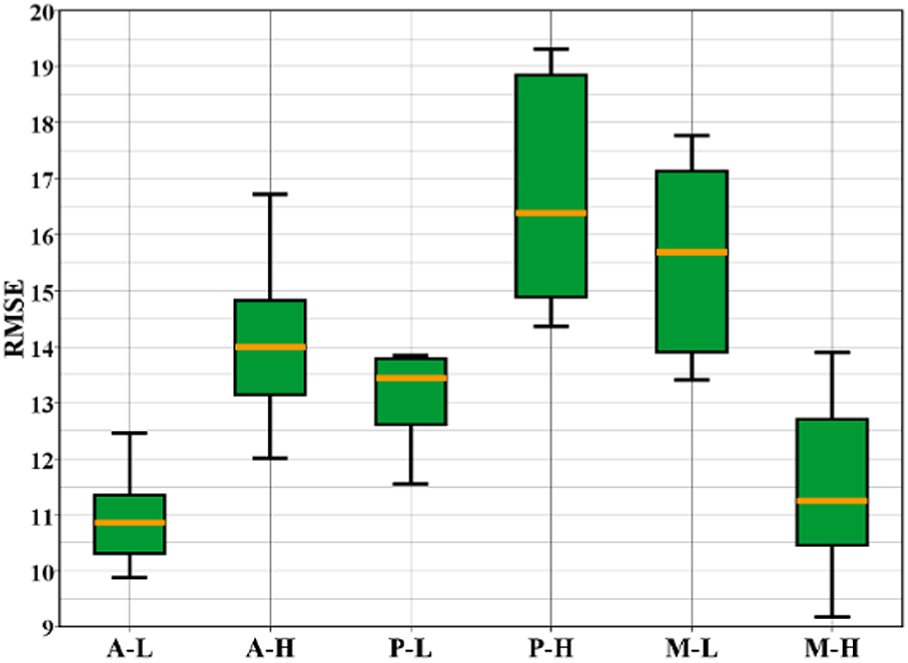
Comparison of recognition accuracy in six trials (RMSE values).
Figure 4 showed 3D maps of the pressure distribution over the contact surface of a subject in six trials, and the differences under different conditions could be observed. There were two conditions of low pressure (30 mmHg) and high pressure (70 mmHg) at the initial collection point. Then, the pressure distribution of the elbow angle at 0° and 90° were measured at three strap positions. Due to the irregularity of upper sections of the arm, the pressure values produced some local peaks. First, the pressure values during the whole movement were basically distributed between 20 and 50 mmHg at the initial low-pressure condition. When the elbow angle was 0°, the pressure distributions were more balanced in the direction of the strap width (upper-arm axial direction), and local peak points were concentrated in the middle. Elbow rotation to 90°, muscle contraction led to increased cross-sectional area of the muscle, the pressure increased. When the elbow angle was 90°, pressure peaks were shifted in the width direction. At the anterior and posterior positions of upper arm, the contact pressure peaks of the straps move to the position of the abdomen, respectively. But the shift was not significant because the initial contact pressure was small. Second, at the initial high-pressure condition, the pressure values were distributed between 50 and 100 mmHg. When the position of the strap was at the anterior and posterior positions of upper arm, that is, at the A-H and P-H conditions, the pressure distributions of 0° and 90° were significantly different, indicating that the rotation of the joint caused a change in the pressure distribution. In contrast, the pressure distribution did not change significantly in the M-H condition.

Pressure distribution of the contact surface at 0° and 90° elbow angles in six trials.
Figure 5 showed pressure curves in the strap width direction at the initial high surface pressure conditions. In the width direction, the strap was divided into 1–6 sections according to the two-dimensional (2D) maps of pressure distribution. Then, the same part of straps was selected in trials, and a pressure mean for each section was calculated separately. In the figure, we marked the selected area with dotted lines. In the M-H condition, the pressure peaks were concentrated in the middle of strap width at 0° and 90° elbow angles. There was still a symmetrical surface pressure distribution before and after the movement, and there was no obvious changes in the shape of curve. However, in the A-H and P-H conditions, the pressure distribution of straps were significantly different before and after the movement. And, pressure peaks appear on both sides of the strap width direction, respectively. Combined with the results of angles recognition, we believe that the consistency of the pressure distribution over the contact surface during the movement has a great effect on the recognition accuracy and more significantly in high-pressure conditions.
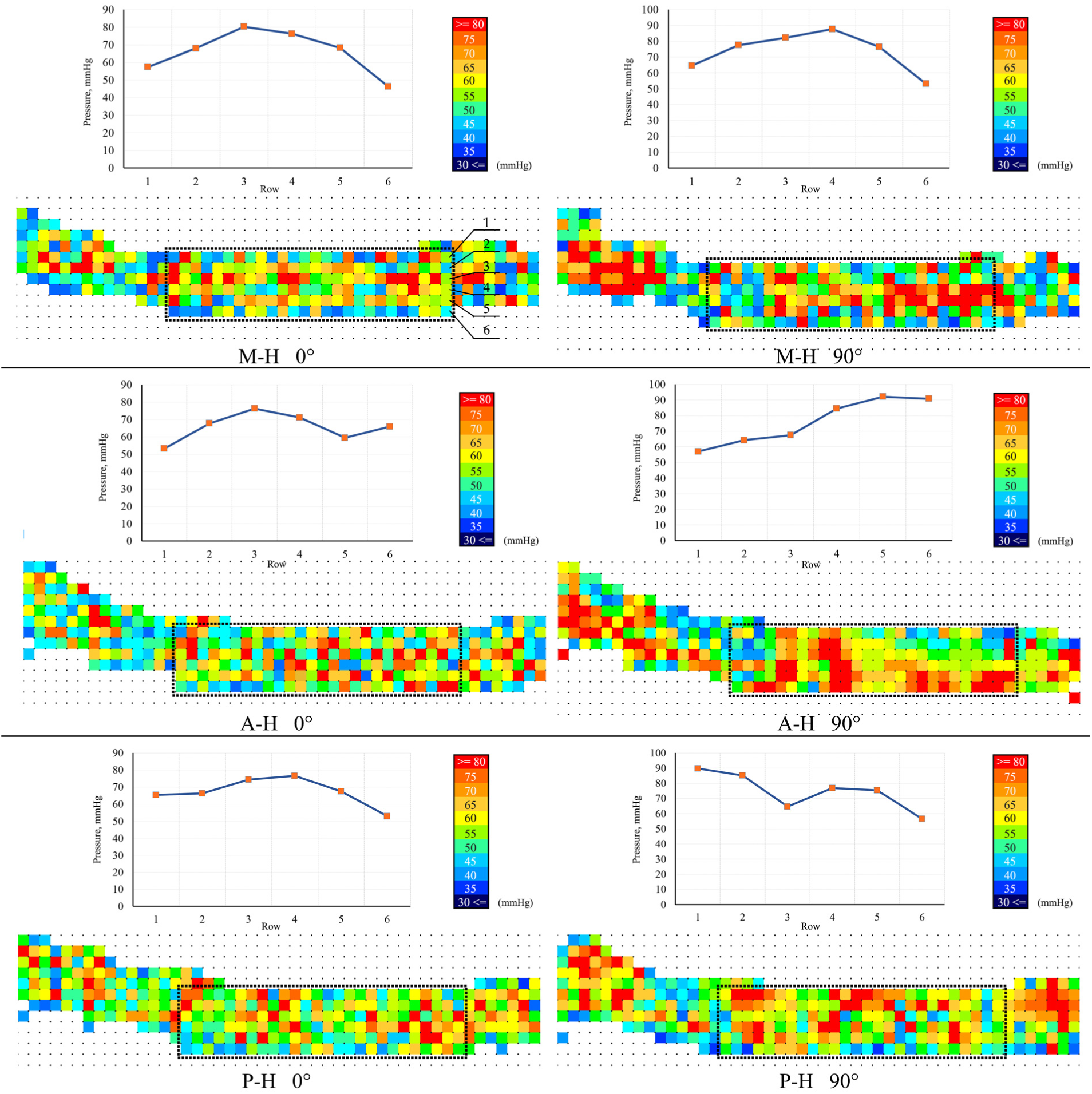
The pressure curve of cross sections in the condition of initial high surface pressure.
Discussion
The contact surface is the essential man–machine interface of wearable device. This study investigated the effect of the strap on multiple muscles activity. Comparing our findings with that of other studies is challenging, particularly because we are the first to evaluate the influence of the strap on the human–device interface through pattern recognition of elbow joint angles. We want to minimize the impact of contact factors on the control accuracy.
From the above results, we conclude that the optimal position of the strap at high pressure is the middle of the upper arm. There may be two reasons for this result. First, the flexion and extension motions of elbow are completed mainly by the biceps and triceps, which contain muscle belly and tendon. The muscle belly produced muscle force in the contraction. The muscle tendon connects the bones and cannot shrink. When the elbow movement is from 0° to 90°, the contraction of the biceps muscle belly increased the circumference of upper arm. The increase in the perimeter was more noticeable under high-pressure conditions. If the lower edge of the strap was located at the tendon position, the upper edge of the strap would be subjected to outward tension generated by the deformation of the muscle belly. The muscle tendon was not able to shrink and deform, so did not cause tension in any direction. The non-uniform force on both sides made the fit worse between the strap and the human body, and the strap was more prone to loosen. Second, there are more blood vessels at the ends of the upper arm to supply blood. High contact pressure could hinder blood circulation and alter the energy demand–energy supply relationship during the contractions giving the appearances of a greater metabolic demand. 19 This change resulted in erratic motion. And, the pressure effected on the muscle (muscle belly position) would slow down the occurrence of above phenomenon greatly and improve the accuracy of recognition. Therefore, when high contact pressure required, the placement of the strap should cover the muscle belly. However, if the initial pressure of the strap is small, the displacement of the pressure distribution is not significant in the joint rotation. The accuracy of the angle prediction will be affected by other factors. Compared to the position of the strap at both ends of the upper arm, the position of the muscle abdomen is closer to the EMG electrode, so it is easy to produce more noise in motion. This is also the reason why the angle recognition accuracy was the lowest in the initial low-pressure condition.
From the results, we believed that the recognition accuracy at the low-pressure condition was superior to the high pressure when the strap was placed at the anterior of upper arm or the posterior of upper arm. But if the strap was located on muscle belly (the middle of the upper arm), the smaller contact pressure could cause slippage. Compared to the tendon position, sEMG signal are more sensitive to slippage, since the muscle belly was closer to the sEMG electrodes. Some scholars studied that a certain external pressure was capable of changing motor unit activation patterns, while an unnecessary muscle activity is decreased, achieving to raise less motor units and to maintain the same output power, and thus, there is a positive effect on the long fatigue performance. 20 We believe this is feasible, but must have a consistent pressure distribution in motion. Our experiments showed that the pressure distribution was more consistent in the middle of upper arm, with no significant change in the position of peak values. Local pressure substantially affected the pattern of muscle involvement (amplitude and frequency). 21 Webster and Roberts 22 concluded that it is important to ensure that straps apply a more consistent pressure particularly during flexion and extension of joint, and average and peak pressure need to be reduced. So, we believed that the consistency of pressure distribution in motion could have a significant effect on the recognition accuracy, especially under high-pressure conditions. There are some difficulties in using ordinary strap to obtain consistent pressure distribution. One possible mechanism is based on an interactive interface using more optimized contact form and area.
Conclusion
As apparent from the data, the interface pressure and the placement have strong influence on the accuracy of recognition. We believe that the setting of these factors is not only ergonomics but also related to the quality of control. Four important points need to be taken into consideration for the contact surface of wearable device to improve efficiency of control, the devices must be able to (1) strap apply a more consistent pressure in motion; (2) the contact pressure is selected appropriately; (3) the choice of contact position should be determined according to the contact pressure. Moreover, an ideal human interfacing device (4) must not cause discomfort or safety hazards for the user during movement.
Footnotes
Handling Editor: Nicolas Garcia-Aracil
Declaration of conflicting interests
The author(s) declared no potential conflicts of interest with respect to the research, authorship, and/or publication of this article.
Funding
The author(s) disclosed receipt of the following financial support for the research, authorship, and/or publication of this article: This study is partly supported by the National Natural Science Foundation of China (No. 61562072), Basic Research Program by Department of Science and Technology of Guizhou Province (Joint funds, No. LH(2017)7232), Guizhou University Academic New Seedling Training and Innovation Project (No. 2017-5788), and Guizhou University Talent Fund (No. 2015-50).