
Abstract
In this article, building a controlled system with velocity feedback in the inner loop for a platform driven by piezoelectric motors is investigated. Such a motion control system is subject to disturbance such as friction, preload, and temperature rise in operation. Especially, temperature rise is an essential problem of using piezoelectric motor, but very few research works address this topic in depth. Exponentially weighted moving average method has been widely used in process control to deal with systematic change and drift disturbance. It is attempted to map the exponentially weighted moving average method and the predictor corrector control with two exponentially weighted moving average formulas into a run-to-run model reference adaptive system for velocity control. Using a predictive friction model, a dead-zone compensator is built that can reduce the friction effect and provide an approximately linear relation of the input voltage and the output velocity for the subsequent exponentially weighted moving average or predictor corrector control control design. Comparison of the exponentially weighted moving average, predictor corrector control, and proportional–integral–derivative controllers is carried out in experiment with different speed patterns on a single-axis and a bi-axial platform. The results indicate that the proposed run-to-run-model reference adaptive system predictor corrector control is superior to the other methods.
Keywords
Introduction
Because of the inherent characteristics of good resolution, small size, and less electro-mechanical impedance (EMI), piezoelectric ceramic motors are popular and are used for high-precision positioning application purposes. Various kinds of piezoelectric motors have been developed in decades and classified into standing wave and traveling wave. Besides the problems of inaccurate assembly or improper preload, these piezoelectric motors are sensitive to temperature rise and their performance becomes worse during long-time operation.1,2 These negative factors are the disadvantages and serious concerns of using piezoelectric motors. Miscellaneous wedge-type piezoelectric motors usually driven by standing wave to propel a carriage via the contact tip were designed to improve the positioning capability and accuracy.3–5 In this article, a wedge-type piezoelectric motor is selected as an example to investigate the disturbance problem of temperature effect in particular.
Friction usually causes a dead-zone area which is another problem. For instance, dead zone is apparent when motion starts as well as manipulates forward and reverse repetitively. 6 Also, small applied voltage is usually assigned for slow speed requirement neighboring to the set-point change, which may render dead zone in particular. Minh et al. compared with three methods of reducing friction effect while using piezoelectric actuator devices to drive a linear platform. From experimental results, they concluded that the friction compensator based on the LuGre model outperforms the bang-bang control based on a static friction model and the friction state observer based on the LuGre model. 7 Lee and Tomizuka designed a control structure coupled with friction compensation for robust high-speed high-accuracy motion control systems. The friction compensator could cope with the friction using a cancellation term in the friction model. 8 Following this method, a dead-zone compensator is also designed in this study. On the basis of a predictive friction model included in the control scheme, a linear input/output relation is available, which is important to the subsequent exponentially weighted moving average (EWMA) and predictor corrector control (PCC) design.
Miscellaneous approaches utilized self-tuning discrete-time control, sliding mode control, genetic algorithm, neural network methods, and so on to deal with the time-varying parameters from nonlinearity and disturbance so as to preserve high-precision positioning while operating with piezoelectric motors.9–11 Therefore, building a suitable robust controller for such a time-varying system is demanding. EWMA algorithm is one of the most basic run-to-run (RtR) control schemes widely used for monitoring and tracking small changes in the volatility. It has been applied to miscellaneous applications like economics, inventory, and quality control. Process drift and environment disturbance are common factors that often occur in many manufacturing processes. The EWMA method has been extensively studied to overcome such problem in recent decades, especially in semiconductor manufacturing processes. Stability conditions for the process encountered drifting or noise for a first-order MISO (multiple-input-single-output) process were derived.12,13 A self-tuning EWMA controller was established to deal with linear drift and random noise, which could improve the semiconductor operating processes. 14 A PCC method on the basis of internal model control (IMC) structure was proposed for etching process to remove the impact of process drift and reduce the offset. 15
As known, the relation between the input voltage applied to the piezoelectric motor and the output velocity of the platform is similar to chemical mechanical polishing (CMP) process with linear relation between the input recipe and the output target. Therefore, an attempt is to use EWMA for velocity control objective. Nonetheless, disturbance due to improper assembly, friction, and temperature rise in operation is similar to the CMP process encountered with systematic change, which would cause the predictive linear relation unlikely to keep and appear bias. Increasing the control effort or even deteriorating the system performance is inevitable. Further investigation of solving this problem is thus necessary. Osburn et al., 16 probably the first ones, proposed the model reference system using the performance index minimization method. This adaptive control scheme later has been proved to be one of the most popular methods in the growing field of adaptive control. 17 A robust adaptive control scheme based upon the model reference for continuous-time system was designed with an unknown input dead zone to achieve both stabilization and tracking within a desired precision. 18 Through adapting system parameters, the problem of model inaccuracy and uncertainty can be overcome so as to gain better robustness. In our previous work, mapping the EWMA into a control system under the IMC configuration was developed. 19 Also, the analytic and experimental results proved that the EWMA with a cascade proportional–integral (PI) controller could efficiently deal with the temperature rise problem of stack-type piezoelectric actuator. In this study, the equivalent transfer function of statistical EWMA and PCC is derived. The PCC with two EWMA formulas is proved to be a combination of an integrator and a double integrator. A new approach of implementing these control methods in a model reference adaptive system (MRAS) to form a velocity feedback control scheme is designed. Various velocity-tracking trajectories of square and trapezoidal types for single-axis platform as well as circular type for bi-axial platform are assigned for these controllers. The experimental results show that the PCC performs better.
Problem statements
Using wedge-type piezoelectric motors to drive a single-axis platform as well as a bi-axial platform is investigated and shown in Figure 1. A nearly linear relation with a constant slope between the applied input voltage and the output velocity of the platform is measured and presented in Figure 2. However, there exists a typical dead zone due to unavoidable friction effect. Besides, a focus in this article is as operating piezoelectric ceramic actuator for a while, so heat is generated to increase temperature around the ceramics. This intrinsic phenomenon deteriorates its performance significantly. In Figure 3, temperature of the piezoelectric motor gradually increases as operation time increases. Using cooling system or intermittent stop during operation may cool down the actuator; however, design of a suitable control method by fully understanding the system behavior subject to temperature rise in operation is the primary goal.

Wedge-type piezoelectric motor structure: (a) single platform and (b) bi-axial platform.

Output (velocity) versus input (command voltage).
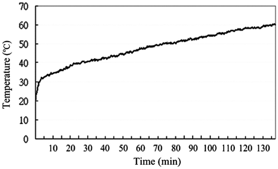
Temperature rise in operation versus time.
Dead-zone compensator
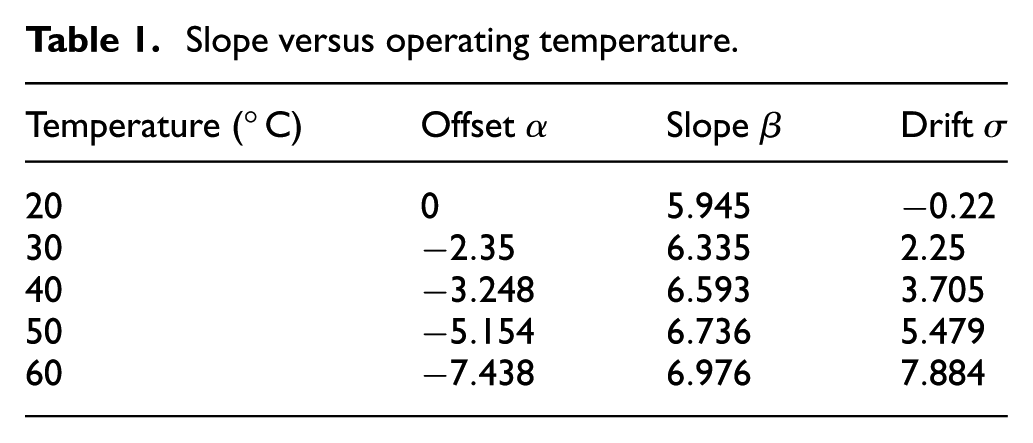
In Figure 2, dead zone occurs in the range of small operating voltage. An equivalent model of the input/output relation is illustrated in Figure 4. 7 An approach to obtain a linear relation depicted in Figure 4(a) is by subtracting Figure 4(b) from Figure 4(c). In this method, the dead zone can be determined based on the voltage-to-velocity profile of the platform in practice. Offset occurs in the region of dead zone and its value may not necessarily be the same in both directions. Depending on the specific driver, motor, and mechanical structure, dead zone can be slightly different. 20 The use of a dead-zone compensator requires the command threshold to be established, which is the point when motion starts. 6 Using the dead-zone compensator, the relation between input voltage and output velocity corresponding to various operating temperatures (20°, 30°, 40°, 50°, 60°) is measured respectively. Figure 5 shows the selected example of operating temperature at 20°C, 40°C, and 60°C. Approximate slopes of the linear relation for various operating temperatures are found and shown in Figure 6. In this study, normal operating condition of temperature about 20°C is chosen as the reference. Based upon the slopes presented in Figure 6, offset is defined as the difference from the zero point and drift is defined as the difference of linear relation, which are both calculated and listed in Table 1. As seen, drift for each operating condition is found with a linearly increasing trend. Also, it is seen that the linear relation is symmetric for positive and negative applied voltage, which represents the forward and reverse motion of the platform.
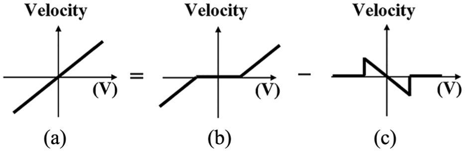
Equivalent output/input model.

Velocity versus applied voltage (20°C, 40°C, and 60°C).

Slope change versus operating temperature.
Slope versus operating temperature.
Controller design
To deal with a time-varying system as addressed above, a modified adaptive control scheme is developed, which applies the RtR control method using EWMA onto an MRAS structure. Based on such a control scheme, additional controller added in the feedback path can enhance the robustness to deal with the deterministic drift. Besides the general EWMA, PCC is also considered for its capability of dealing with the drift problem. With the MRAS velocity control loop, an outer loop is simply constructed for positioning control purpose so as to complete a dual control loop.
Modified MRAS
The structure of MRAS for velocity feedback control is illustrated in Figure 7, where

EWMA or PCC controller embedded on an MRAS structure.
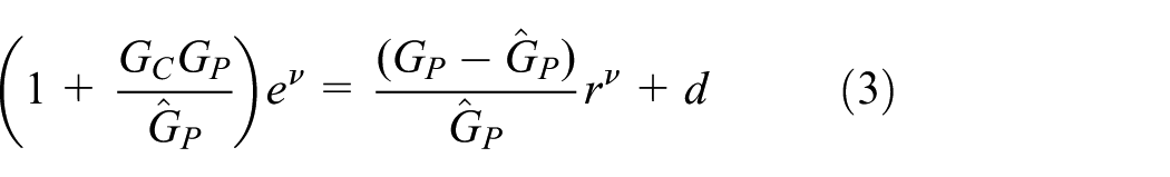
As illustrated in Figure 7, it gives
where

Equation (2) is rewritten as
It is assumed that the input

EWMA controller
While the dead zone is eliminated, an approximate linear relation of the input (applied voltage) and output (velocity) can be described by 21

where
The predictive model is defined by Guo et al. 21

where

and the estimated parameter can be adapted by

where
By writing equation (9) for two successive runs and substituting equation (8) into it, the estimated parameter is rewritten as

where
A discrete-time expression for equation (10) is derived as

According to Figure 7, the EWMA controller is defined as


Further investigation of the system model either static or dynamic is also concerned.
Dynamic model
It is noted that using the static model

where coefficients

Step input response.

Performance of using static or dynamic model.
Stability condition for EWMA
According to Figure 6, the linear relation between the input voltage and output speed is obtained with a constant slope

As seen, the characteristic equation is

By the Jury stability test, 22 the following bounds for the stability region of the RtR-EWMA discrete-time controller embedded on an MRAS structure are given by

For weighting factor

This derived stability condition is same as the conditional convergence for the EWMA controller addressed by Ingolfsson and Sachs.
12
The stability region for
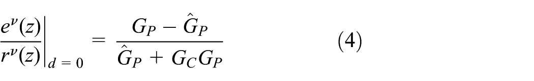
For step input, the tracking error

As seen, the steady-state error of the system converges to zero; in other words, the output
Disturbance and steady-state error
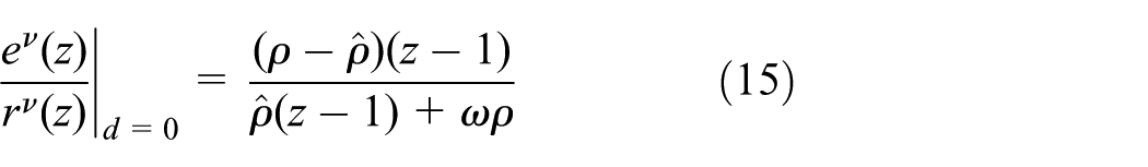
As described above, the suitable operating condition of temperature is assigned as 20°C, which is chosen as the reference index. As seen in Figure 6, a linear drift exists, which is treated as a deterministic ramp disturbance in the sense of control design. In equation (15), the error due to a ramp disturbance becomes

where
PCC controller
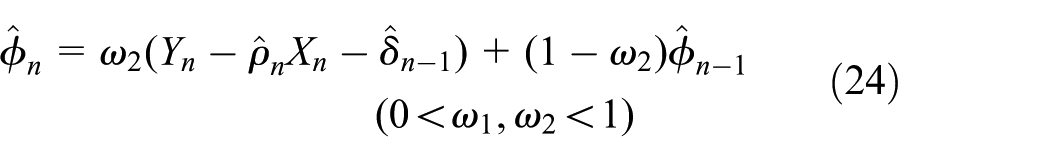
As described above, the EWMA controller is not able to deal with the problem of ramp-type disturbance theoretically. Instead of using EWMA with one-stage estimation, a PCC is proposed with two-stage parameter estimation 15 and expressed by
where

Equation (23) can be rewritten as

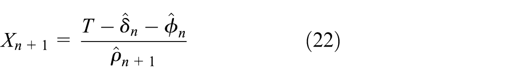
A discrete-time expression for equation (25) is derived as
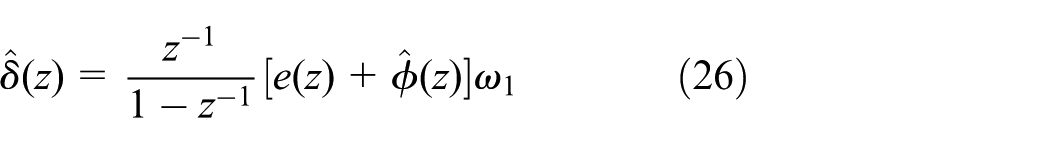
Similarly, equation (24) can be rewritten as

A discrete-time expression for equation (27) is derived as

From equations (26) and (28), it yields

Hence, it is seen that the PCC contains an integrator as well as a double integrator as shown in equation (29).
Stability condition for PCC controller
According to Figure 7 and equation (29), the transfer function of the equivalent PCC controller in the MRAS structure can be derived as
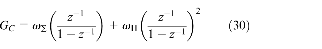
where
Then, the transfer functions for

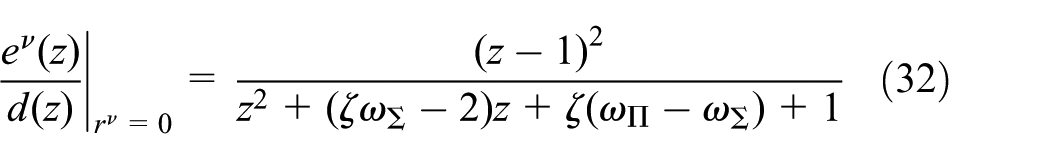
where
The characteristic equation of (31) and (32) can be expressed as

Using the Jury stability test, the stability conditions are determined as

Substituting

From (i) in equation (35), it can be concluded that
and

From equations (36) and (37), it is clear to conclude

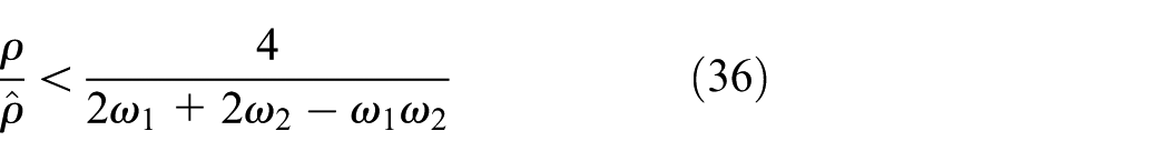
Thus, the stability bound of the PCC controller in the MRAS structure is chosen as

An attempt is to narrow the region of choosing weighting factors

then
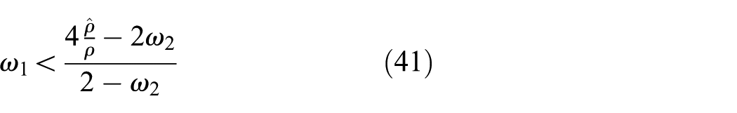
Thus, the feasible region of

Appropriate weighting factors
Disturbance and steady-state error of PCC controller
PCC is proved as an integral-double-integral controller (I-II) in equation (30) and in previous research.15,21 As seen, PCC is quite similar to EWMA but with two-stage parameter estimation. Besides adjustment of the estimate parameter

Therefore, PCC is able to overcome the problem of process drift and converge to the desired target, which is also proved by statistical control method in terms of the expected value and variance.21,23
Experiment and discussion
A single-axis platform and a bi-axial platform driven by wedge-type piezoelectric motors were used for testing. An optical quadrature encoders (MicroE Systems II 5600 with 1.22 nm resolution per count) connected to NI PCI-DAQ 6229 via DB-15 was used to provide feedback of the instantaneous position and velocity for the platform. Sampling period of 5 ms is chosen for using a regular PC-based control system. Based on the feasible region defined in equation (38), the weighting factors for EWMA and PCC are selected to be
For a single-axis platform, two types of tests were chosen with arbitrarily chosen trajectories (square command standing for constant velocity and trapezoidal command standing for constant velocity and acceleration). The platform is driven continuously by piezoelectric motor from temperature 20°C up to 60°C. Selected examples of operating temperature (20°C, 40°C, 60°C) are presented with implementation of PID, EWMA, and PCC control methods associated with the dead-zone compensator. Velocity-tracking performances for square command and trapezoidal command are shown in Figures 10–15. The root-mean-square error (RMSE) and error overshoot computed for each case are presented in Tables 2–5. Since the trapezoidal command is a smoother trajectory, it is apparently seen that the RMSE of the trapezoidal command is smaller than that of the square command. From the results, it indicates that PCC outperforms EWMA controller as expected. Both EWMA and PCC perform better than the PID controller. It is obvious to see the PCC controller has the advantages of minimum overshoot while moving direction (forward and reverse) is changing as shown in (b) and (c) of Figures 10–12. Also, velocity-tracking performance is focused on the critical condition of set-point change during the switching from acceleration to constant velocity as shown in (b) and (c) of Figures 13–15. It is found that the PCC controller has the smallest error on an average. As the temperature increases, the tracking error and overshoot are more serious. Hence, a conclusion is drawn that the proposed PCC controller preserves better performance.

Velocity-tracking and error performance (20°C): (a) tracking performance, (b) tracking error, and (c) zoom of (b).

Velocity-tracking and error performance (40°C): (a) tracking performance, (b) tracking error, and (c) zoom of (b).

Velocity-tracking and error performance (60°C): (a) tracking performance, (b) tracking error, and (c) zoom of (b).
Velocity-tracking error (mm/s)—square.

PID: proportional–integral–derivative; EWMA: exponentially weighted moving average; PCC: predictor corrector control.
Velocity-tracking error overshoot—square.

PID: proportional–integral–derivative; EWMA: exponentially weighted moving average; PCC: predictor corrector control.
Velocity-tracking error (mm/s)—trapezoidal.

PID: proportional–integral–derivative; EWMA: exponentially weighted moving average; PCC: predictor corrector control.
Velocity-tracking error overshoot—trapezoidal.
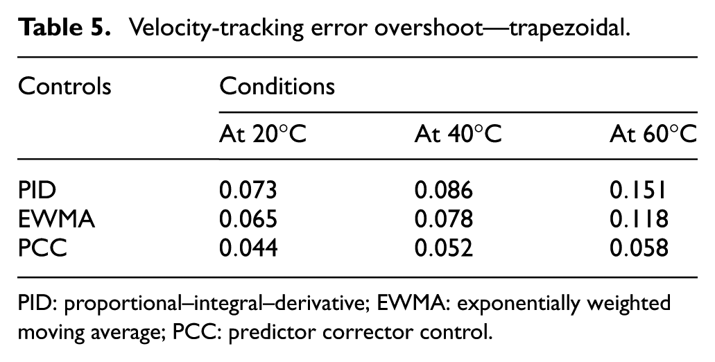
PID: proportional–integral–derivative; EWMA: exponentially weighted moving average; PCC: predictor corrector control.
A contour test is also carried out on a bi-axial platform to evaluate the performance of the proposed control method with sinusoidal command. As presented in Figure 16, a circular trajectory with a stroke of diameter 20 mm is tested under operating temperature 60°C. A simple position feedback is designed in the outer loop for tracking position. In the zoom area, it is seen the PCC preserves better positioning accuracy. The tracking performance on x-axis and y-axis are shown in Figures 17–20 as well as listed in Table 6. The tracking performance on both axes shows that norm of the error of the proposed PCC control method is (0.3475) mm/s is superior to the EWMA and PID with (0.4433) mm/s and (0.6333) mm/s, respectively.

Compilation of contour tracking plot (20 mm).

Velocity-tracking plot of x-axis (20 mm).

Velocity-tracking error of x-axis (20 mm).

Velocity-tracking plot of y-axis (20 mm).

Velocity-tracking error of y-axis (20 mm).
Norm of error (mm/s) on 20-mm circular trajectory.

PID: proportional–integral–derivative; EWMA: exponentially weighted moving average; PCC: predictor corrector control.
Conclusion
With a dead-zone compensator, friction is effectively reduced to give an approximate linear input/output relation for the following control design using EWMA or PCC. Temperature rise in operation affects the system performance significantly, which is one of the main focuses in this article. From experiment, the effect due to temperature rise is found as a linear drift bias and treated as a deterministic ramp disturbance. Based upon the configuration of an MRAS, a velocity feedback control employed with EWMA or PCC method is developed. The error due to ramp disturbance is calculated and verified to be the same as that using statistical control. As expected, the PCC is able to cope with the ramp disturbance caused by temperature rise while operating piezoelectric motors. Mapping onto a control block diagram and under a configuration of MRAS also gives a convenient way in design and analysis. Different speed patterns for a single-axis platform and a circular planar motion for a bi-axial platform are carried out to verify the effectiveness of the proposed method. All the testing results indicate that the EWMA and PCC controllers are verified to outperform the PID with optimal gains and PCC is superior to the other methods.
Footnotes
Handling Editor: Mario L Ferrari
Declaration of conflicting interests
The author(s) declared no potential conflicts of interest with respect to the research, authorship, and/or publication of this article.
Funding
The author(s) disclosed receipt of the following financial support for the research, authorship, and/or publication of this article: This research was supported by the National Science Council under the grant NSC101-2622-E-033-001-CC2 and Soundwide Technology Corp.